Page 65 of 296
 studs approximately
90 mm long, with a")
25As the cylinder head is such a heavy and
awkward assembly to refit with manifolds, it is
helpful to make up a pair of guide studs from
two 10 mm (thread size) studs approximately
90 mm long, with a screwdriver slot cut in one
end - two old cylinder head bolts with their
heads cut off would make a good starting
point. Screw these guide studs, screwdriver
slot upwards to permit removal, into the bolt
holes at diagonally-opposite corners of the
cylinder block surface (or into those where the
locating dowels are fitted); ensure that
approximately 70 mm of stud protrudes
above the gasket.
26 Refit the cylinder head, sliding it down the
guide studs (if used) and locating it on the
dowels. Unscrew the guide studs (if used)
when the head is in place.
27 Fit the new cylinder head bolts dry ( do not
oil their threads); carefully enter each into its
hole and screw it in, by hand only, until finger-
tight.
28 Working progressively and in the
sequence shown, use first a torque wrench,
then an ordinary socket extension bar and an
angle gauge, to tighten the cylinder head bolts
in the stages given in the Specifications
Section of this Chapter (see illustrations).
Note: Once tightened correctly, following this
procedure, the cylinder head bolts do not
require check-tightening, and must notbe re-
torqued.
29 Refit the hydraulic tappets (if removed),
the camshafts, their oil seals and sprockets
(see Sections 11, 10 and 9, as appropriate).
Temporarily refit the crankshaft pulley, and
rotate the crankshaft clockwise to return the
pulley notches to the TDC position described
in Section 3.
30 Refit the earth lead to the lifting eye
31 Refit the timing belt and covers, checking
the camshaft alignment (valve timing) and
setting the timing belt tension, as described in
Section 8.
32 The remainder of reassembly is the
reverse of the removal procedure, noting the
following points:
a) Tighten all fasteners to the torque wrench settings specified.
b) Refill the cooling system, and top-up the engine oil (see Chapter 1 and “Weekly
Checks”).
c) Check all disturbed joints for signs of oil or coolant leakage, once the engine has
been restarted and warmed-up to normal
operating temperature.
d) If the power steering hoses where
disconnected, bleed the system as
described in Chapter 10 after
reconnection.
13 Sump -
removal and refitting
2
Removal
Note: The full procedure outlined below must
be followed, so that the mating surfaces can
be cleaned and prepared to achieve an oil-
tight joint on reassembly, and so that the
sump can be aligned correctly; depending on
your skill and experience, and the tools and
facilities available, it may be that this task can
be carried out only with the engine removed
from the vehicle. Note that the sump gasket
must be renewed whenever it is disturbed.
1 Disconnect the battery negative (earth) lead
(refer to Chapter 5A, Section 1).
2 Drain the engine oil, then clean and refit the
engine oil drain plug, tightening it to the
specified torque wrench setting. Although not
strictly necessary as part of the dismantling
procedure, owners are advised to remove and
discard the oil filter, so that it can be renewed
with the oil (see Chapter 1).
3 Refer to Chapter 5A and remove the starter
motor.
4 Remove the auxiliary drivebelt cover (see
Chapter 1).
5 Unplug the electrical connector(s) to
disconnect the oxygen sensor.
6 Unscrew the nuts to disconnect the
exhaust system front downpipe from the
manifold, then either unhook all the system’s
rubber mountings and withdraw the complete
exhaust system from under the vehicle, or
remove only the downpipe/catalytic converter
(see Chapter 4E for details). 7
Unscrew the sump-to-transmission bolts,
also any securing the engine/transmission
lower adapter plate.
8 Progressively unscrew the sump retaining
bolts. Break the joint by striking the sump with
the palm of the hand, then lower the sump
and withdraw it with the engine/transmission
lower adapter plate (where fitted); note the
presence of any shims between the sump and
transmission.
9 Remove and discard the sump gasket; this
must be renewed as a matter of course
whenever it is disturbed.
10 While the sump is removed, take the
opportunity to remove the oil pump pick-
up/strainer pipe and to clean it (see Sec-
tion 14).Refitting
11 On reassembly, thoroughly clean and
degrease the mating surfaces of the cylinder
block/crankcase and sump, then use a clean
rag to wipe out the sump and the engine’s
interior. If the oil pump pick-up/strainer pipe
was removed, fit a new gasket and refit the
pipe, tightening its screws to the specified
torque wrench setting. Fit the new gasket to
the sump mating surface so that the gasket
fits into the sump groove (see illustration).
12 If the sump is being refitted with the
engine/transmission still connected and in the
vehicle, proceed as follows:
a) Check that the mating surfaces of the sump, the cylinder block/crankcase and
2C•12 Zetec engine in-car repair procedures
13.11 Ensure gasket is located correctly in sump groove
12.28c . . . and to Stage 3 using angle gauge12.28b Tightening cylinder head bolts
(Stages 1 and 2) using torque wrench . . .12.28a Cylinder head bolt tightening sequence
Note: View from rear of vehicle
1595Ford Fiesta Remakeprocarmanuals.com
http://vnx.su
Page 66 of 296
 Apply a thin film of suitable sealant (Ford
recommend Hylosil 10")
the transmission are absolutely clean and
flat. Any shims found on removal of the
sump must be refitted in their original
locations.
b) Apply a thin film of suitable sealant (Ford
recommend Hylosil 102) to the junctions
of the cylinder block/crankcase with the
oil pump and the crankshaft left-hand oil
seal carrier. Without delay - the sump
bolts must be fully tightened within 10 to
20 minutes of applying the sealant - offer
up the sump and engine/transmission
lower adapter plate, and refit the bolts,
tightening them lightly at first.
c) Ensuring that the engine/transmission
lower adapter plate is correctly located,
firmly press the sump against the
transmission, and tighten the
transmission-to-sump (ie, engine) bolts to
the specified torque wrench setting.
d) Without disturbing the position of the
sump, and working in a diagonal
sequence from the centre outwards,
tighten the sump bolts to the specified
torque wrench setting.
e) Proceed to paragraph 14.
13 If the sump is being refitted with the
engine and transmission separated (in or out
of the vehicle), proceed as follows:
a) Apply a thin film of suitable sealant (Ford recommend Hylosil 102) to the junctions
of the cylinder block/crankcase with the
oil pump and the crankshaft left-hand oil seal carrier (see illustration). Without delay
- the sump bolts must be fully tightened
within 10 to 20 minutes of applying the
sealant - offer up the sump to the cylinder
block/crankcase, and insert the sump
bolts, tightening them lightly at first.
b) Using a suitable straight edge to check
alignment across the flat-machined faces
of each, move the sump as necessary so
that its left-hand face - including any
shims found on removal - is flush with
that of the cylinder block/crankcase (see
illustration) . Without disturbing the
position of the sump, and working in a
diagonal sequence from the centre
outwards, tighten the sump bolts to the
specified torque wrench setting.
c) Check again that both faces are flush
before proceeding; if necessary, unbolt
the sump again, clean the mating
surfaces, and repeat the full procedure to
ensure that the sump is correctly aligned.
d) If it is not possible to achieve exact
alignment by moving the sump, shims are
available in thicknesses of 0.25 mm
(colour-coded yellow) or 0.50 mm (colour-
coded black) to eliminate the discrepancy
(see illustration) .
14 The remainder of reassembly is the
reverse of the removal procedure, noting the
following points.
a) Tighten all fasteners to the torque wrench settings specified. b)
Always renew any self-locking nuts
disturbed on removal.
c) Refill the cooling system (see Chapter 1).
d) Refill the engine with oil, remembering
that you are advised to fit a new filter (see
Chapter 1).
e) Check for signs of oil or coolant leaks once the engine has been restarted and
warmed-up to normal operating
temperature.
14 Oil pump - removal,
inspection and refitting
4
Removal
Note: While this task is theoretically possible
when the engine is in place in the vehicle, in
practice, it requires so much preliminary
dismantling, and is so difficult to carry out due
to the restricted access, that owners are
advised to remove the engine from the vehicle
first. Note, however, that the oil pump
pressure relief valve can be removed with the
engine in situ - see paragraph 8.
1 Remove the timing belt (see Section 8).
2 Withdraw the crankshaft sprocket and the
thrustwasher behind it, noting which way
round the thrustwasher is fitted (see Sec-
tion 9).
3 Remove the sump (see Section 13).
4 Undo the screws securing the oil pump
pick-up/strainer pipe to the pump, then
unscrew the nut and withdraw the oil pump
pick-up/strainer pipe. Discard the gasket.
5 Unbolt the pump from the cylinder
block/crankcase (see illustration). Withdraw
and discard the gasket, and remove the
crankshaft right-hand oil seal. Thoroughly
clean and degrease all components,
particularly the mating surfaces of the pump,
the sump, and the cylinder block/crankcase.
Inspection
6 Unscrew the Torx screws, and remove the
pump cover plate; noting any identification
marks on the rotors, withdraw the rotors (see
illustration) .
Zetec engine in-car repair procedures 2C•13
13.13c Sump-to-cylinder block/crankcase
alignment shims
1 Fitting points on sump 2 Shim13.13b Checking alignment of sump with cylinder block/crankcase13.13a Apply sealant (arrowed) as directed when refitting sump
14.6 Withdrawing oil pump inner rotor14.5 Unscrew bolts (arrowed) to remove oil pump
2C
1595Ford Fiesta Remakeprocarmanuals.com
http://vnx.su
Page 67 of 296

7Inspect the rotors for obvious signs of wear
or damage, and renew if necessary; if either
rotor, the pump body, or its cover plate are
scored or damaged, the complete oil pump
assembly must be renewed.
8 The oil pressure relief valve can be
dismantled, if required, without disturbing the
pump. Chock the rear wheels then jack up the
front of the car and support it on axle stands
(see “Jacking and Vehicle Support” ). Remove
the front right-hand roadwheel and auxiliary
drivebelt cover (see Chapter 1) to provide
access to the valve.
9 Unscrew the threaded plug, and recover
the valve spring and plunger (see
illustrations) . If the plug’s sealing O-ring is
worn or damaged, a new one must be
obtained, to be fitted on reassembly.
10 Reassembly is the reverse of the dismantling procedure; ensure the spring and
valve are refitted the correct way round, and
tighten the threaded plug securely.
Refitting
11
The oil pump must be primed on
installation, by pouring clean engine oil into it,
and rotating its inner rotor a few turns.
12 Using grease to stick the new gasket in
place on the cylinder block/crankcase, and
rotating the pump’s inner rotor to align with
the flats on the crankshaft, refit the pump and
insert the bolts, tightening them lightly at first
(see illustration) .
13 Using a suitable straight edge and feeler
gauges, check that the pump is both centred
exactly around the crankshaft, and aligned
squarely so that its (sump) mating surface is
exactly the same amount - between 0.3 and
0.8 mm - below that of the cylinder
block/crankcase on each side of the
crankshaft (see illustration) . Being careful
not to disturb the gasket, move the pump into
the correct position, and tighten its bolts
to the specified torque wrench setting.
14 Check that the pump is correctly located;
if necessary, unbolt it again, and repeat the
full procedure to ensure that the pump is
correctly aligned.
15 Fit a new crankshaft right-hand oil seal
(see Section 15).
16 Using grease to stick the gasket in place
on the pump, refit the pick-up/strainer pipe,
tightening its screws and nut to their specified
torque wrench settings (see illustration).17
The remainder of reassembly is the
reverse of the removal procedure, referring to
the relevant text for details where required.15 Crankshaft oil seals -
renewal
4
Note: Don’t try to prise these seals out without
removing the oil pump or seal carrier - the
seals are too soft, and the amount of space
available is too small, for this to be possible
without considerable risk of damage to the seal
housing and/or the crankshaft journal. Follow
exactly the procedure given below.
Right-hand seal
1 Remove the oil pump (see Section 14).
2 Drive the oil seal out of the pump from
behind (see illustration) .
3 Clean the seal housing and crankshaft,
polishing off any burrs or raised edges, which
may have caused the seal to fail in the first
place.
4 Refit the oil pump (see Section 14). Grease
the lips and periphery of the new seal, to ease
installation.
5 To fit a new seal, Ford recommend the use
of their service tool 21-093A, with the
crankshaft pulley bolt, to draw the seal into
place; an alternative can be arranged using a
socket of suitable size, with a washer to
match the crankshaft pulley bolt (see
illustration) .
2C•14Zetec engine in-car repair procedures
15.5 Socket of correct size can be used to
replace Ford service tool, drawing new
seal into place as described15.2 Driving out crankshaft right-hand oil seal14.16 Use new gasket when refitting oilpick-up pipe to pump
14.13 Oil pump must be positioned accurately
14.12 Use new gasket when refitting oil pump14.9b . . . to withdraw oil pressure reliefvalve spring and plunger14.9a Unscrew threaded plug - seenthrough right-hand wheel arch . . .
1595Ford Fiesta Remakeprocarmanuals.com
http://vnx.su
Page 68 of 296

6If such tools are not available, press the
seal squarely into place by hand; tap it in until
it is flush with the pump housing, using a soft-
faced mallet and a socket with an outside
diameter only slightly smaller than the seal’s
(see illustration) . This approach requires
great care, to ensure that the seal is fitted
squarely, without distortion or damage.
7 Wash off any traces of oil. The remainder of
reassembly is the reverse of the removal
procedure, referring to the relevant text for
details where required. Check for signs of oil
leakage when the engine is restarted.
Left-hand seal
8 Remove the transmission (see the relevant
Part of Chapter 7).
9 Where appropriate, remove the clutch
(Chapter 6).
10 Unbolt the flywheel/driveplate (see
Section 17).
11 Remove the sump (see Section 13).
12 Unbolt the oil seal carrier (see
illustration) . Remove and discard its gasket.
13 Supporting the carrier evenly on wooden
blocks, drive the oil seal out of the carrier from
behind (see illustration) .
14 Clean the seal housing and crankshaft,
polishing off any burrs or raised edges, which
may have caused the seal to fail in the first
place. Clean also the mating surfaces of the
cylinder block/crankcase and carrier, using a scraper to remove all traces of the old gasket
- be careful not to scratch or damage the
material of either - then use a suitable solvent
to degrease them.
15
Use grease to stick the new gasket in
place on the cylinder block/crankcase, then
offer up the carrier (see illustration).
16 Using a suitable straight edge and feeler
gauges, check that the carrier is both centred
exactly around the crankshaft, and aligned
squarely so that its (sump) mating surface is
exactly the same amount - between 0.3 and
0.8 mm - below that of the cylinder
block/crankcase on each side of the
crankshaft (see illustration) . Being careful
not to disturb the gasket, move the carrier into
the correct position, and tighten its bolts to
the specified torque wrench setting.
17 Check that the carrier is correctly located;
if necessary, unbolt it again, and repeat the
full procedure to ensure that the carrier is
correctly aligned.
18 Ford’s recommended method of seal
fitting is to use service tool 21-141, with two
flywheel bolts to draw the seal into place. If
this is not available, make up a guide from a
thin sheet of plastic or similar, lubricate the
lips of the new seal and the crankshaft
shoulder with grease, then offer up the seal,
with the guide feeding the seal’s lips over the
crankshaft shoulder (see illustration) . Press
the seal evenly into its housing by hand only, and use a soft-faced mallet gently to tap it
into place until it is flush with the surrounding
housing.
19
Wipe off any surplus oil or grease; the
remainder of the reassembly procedure is the
reverse of dismantling, referring to the relevant
text for details where required. Check for signs
of oil leakage when the engine is restarted.
16 Engine/transmission mountings -
inspection and renewal
1
Inspection
1 The engine/transmission mountings seldom
require attention, but broken or deteriorated
mountings should be renewed immediately, or
the added strain placed on the driveline
components may cause damage or wear.
2 During the check, the engine/transmission
must be raised slightly, to remove its weight
from the mountings.
3 Chock the rear wheels then jack up the
front of the car and support it on axle stands
(see “Jacking and Vehicle Support” ). Position
a jack under the sump, with a large block of
wood between the jack head and the sump,
then carefully raise the engine/transmission
just enough to take the weight off the
mountings.
Zetec engine in-car repair procedures 2C•15
15.13 . . . and ensure that carrier is
properly supported when driving out used oil seal - note notches provided in carrier for drift15.12 Unscrew bolts (arrowed) to removecrankshaft left-hand oil seal carrier . . .15.6 If seal is tapped into place as shown,exercise great care to prevent seal from being damaged or distorted
15.18 Using guide made from thin sheet ofplastic to slide oil seal lips over crankshaft
shoulder15.16 Oil seal carrier must be positionedaccurately15.15 Use new gasket when refitting left-hand oil seal carrier
2C
1595Ford Fiesta Remakeprocarmanuals.com
http://vnx.su
Page 69 of 296

4Check the mountings to see if the rubber is
cracked, hardened or separated from the
metal components. Sometimes, the rubber
will split right down the centre.
5 Check for relative movement between each
mounting’s brackets and the engine/
transmission or body (use a large screwdriver
or lever to attempt to move the mountings). If
movement is noted, lower the engine and
check-tighten the mounting fasteners.
Renewal
6 The engine mountings can be removed if
the weight of the engine/transmission is
supported by one of the following alternative
methods.
7 Either support the weight of the assembly
from underneath using a jack and a suitable
piece of wood between the jack saddle and
the sump or transmission (to prevent
damage), or from above by attaching a hoist
to the engine. A third method is to use a
suitable support bar with end pieces which
will engage in the water channel each side of
the bonnet lid aperture. Using an adjustable
hook and chain connected to the engine, the
weight of the engine and transmission can
then be taken from the mountings.
Engine front right-hand mounting
8 This mounting consists of a two-piece
bracket bolted to the inner wing panel,
connected by the bonded-rubber mounting
itself to a (Y-shaped) bracket, bolted (via the
alternator mounting bracket) to the cylinder
block (see illustration) .
9 Unscrew the three bolts securing the front
right-hand mounting bracket to the alternator
mounting bracket.
10 Unscrew the bolts securing the mounting
bracket to the inner wing panel and chassis
rail and withdraw the mounting assembly.
Engine rear right-hand mounting
11 This mounting consists of the bonded-
rubber mounting secured to the inner wing
panel by a (horizontal) bolt, accessible from
within the wheel arch, and a (vertical) stud, the
retaining nut of which is accessible from the
engine compartment. The mounting is bolted
to a bracket, which is in turn bolted to the
cylinder block.
12 Unbolt the mounting from the body by
unscrewing first the single nut (and washer)
immediately to the rear of the timing belt
cover, then the bolt in the wheel arch.
13 Unbolt the mounting from the cylinder
block bracket and withdraw the mounting
assembly.
Transmission bearer and mountings
14 On XR2i models, remove the front
suspension crossmember as described in
Chapter 10.
15 Unscrew and remove the two nuts
securing the mountings (front and rear) to the
transmission bearer
16 Support the transmission bearer, then
undo and remove the four retaining bolts from
the floorpan, two at the front and two at the
rear, and lower the transmission bearer from
the vehicle. Note plate fitment, as applicable,
for reassembly.
17 To remove the mountings from the
transmission, unscrew the upper bolt and
lower stud (front mounting) or the three nuts
(rear mounting) and withdraw the relevant
mounting and bracket assembly from the
transmission.
All mountings
18 Refitting of all mountings is a reversal of
removal. Make sure that the original sequence
of assembly of washers and plates is
maintained.
19 Do not fully tighten any mounting bolts
until they are all located. As the mounting
bolts and nuts are tightened, check that the
mounting rubbers do not twist.
17 Flywheel/driveplate -
removal, inspection and
refitting
3
Removal
1 Remove the transmission (see the relevant
Part of Chapter 7).
2 Where appropriate, remove the clutch
(Chapter 6).
3 Use a centre-punch or paint to make alignment marks on the flywheel/driveplate
and crankshaft, to ensure correct alignment
during refitting.
4
Prevent the flywheel/driveplate from turning
by locking the ring gear teeth, or by bolting a
strap between the flywheel/driveplate and the
cylinder block/crankcase. Slacken the bolts
evenly until all are free.
5 Remove each bolt in turn, and ensure that
new replacements are obtained for
reassembly; these bolts are subjected to
severe stresses, and so must be renewed,
regardless of their apparent condition,
whenever they are disturbed.
6 Noting the reinforcing plate (automatic
transmission models only), withdraw the
flywheel/driveplate; do not drop it - it is very
heavy.
Inspection
7 Clean the flywheel/driveplate to remove
grease and oil. Inspect the surface for cracks,
rivet grooves, burned areas and score marks.
Light scoring can be removed with emery
cloth. Check for cracked and broken ring gear
teeth. Lay the flywheel/driveplate on a flat
surface, and use a straight edge to check for
warpage.
8 Clean and inspect the mating surfaces of
the flywheel/driveplate and the crankshaft. If
the crankshaft left-hand seal is leaking, renew
it (see Section 15) before refitting the
flywheel/driveplate.
9 While the flywheel/driveplate is removed,
clean carefully its inboard (right-hand) face,
particularly the recesses which serve as the
reference points for the crankshaft speed/
position sensor. Clean the sensor’s tip, and
check that the sensor is securely fastened.
Refitting
10 On refitting, ensure that the engine/
transmission adapter plate is in place (where
necessary), then fit the flywheel/driveplate to
the crankshaft so that all bolt holes align - it
will fit only one way - check this using the
marks made on removal. Do not forget the
reinforcing plate (automatic transmission
models).
11 Lock the flywheel/driveplate by the
method used on dismantling. Working in a
diagonal sequence to tighten them evenly,
and increasing to the final amount in two or
three stages, tighten the new bolts to the
specified torque wrench setting.
12 The remainder of reassembly is the
reverse of the removal procedure, referring to
the relevant text for details where required.
2C•16 Zetec engine in-car repair procedures
16.8 Engine front right-hand mounting
1595Ford Fiesta Remakeprocarmanuals.com
http://vnx.su
Page 70 of 296
 . . . . . . . . . . . . . . . . . . . . . . . . . . . . . . . . . . . .\")
2D
1595Ford Fiesta Remake
HCS engines
Cylinder head
Maximum permissible gasket surface distortion (measured over
full length) . . . . . . . . . . . . . . . . . . . . . . . . . . . . . . . . . . . .\
. . . . . . . . . . . . 0.15 mm
Valve seat angle (inlet and exhaust) . . . . . . . . . . . . . . . . . . . . . . . . . . . . 45º
Valve seat width (inlet and exhaust) . . . . . . . . . . . . . . . . . . . . . . . . . . . . 1.18 to 1.75 mm*
*The inlet and exhaust valves have special inserts which cannot be recut\
using conventional tools.
Valves - generalInletExhaust
Valve length . . . . . . . . . . . . . . . . . . . . . . . . . . . . . . . . . . . .\
. . . . . . . . . . 103.7 to 104.4 mm 104.2 to 104.7 mm
Valve head diameter: 1.0 and 1.1 litre engines . . . . . . . . . . . . . . . . . . . . . . . . . . . . . . . . . . . 32.90 to 33.10 mm 28.90 to 29.10 mm
1.3 litre engines . . . . . . . . . . . . . . . . . . . . . . . . . . . . . . . . . . . .\
. . . . . . 34.40 to 34.60 mm 28.90 to 29.10 mm
Valve stem diameter . . . . . . . . . . . . . . . . . . . . . . . . . . . . . . . . . . . .\
. . . . 7.0 mm 7.0 mm
Valve stem-to-guide clearance . . . . . . . . . . . . . . . . . . . . . . . . . . . . . . . . 0.020 to 0.069 0.046 to 0.095
Cylinder block
Cylinder bore diameter: 1.0 and 1.1 litre engines:
Standard class 1 (or A) . . . . . . . . . . . . . . . . . . . . . . . . . . . . . . . . . . 68.68 to 68.69 mm
Standard class 2 (or B) . . . . . . . . . . . . . . . . . . . . . . . . . . . . . . . . . . 68.69 to 68.70 mm
Standard class 3 (or C) . . . . . . . . . . . . . . . . . . . . . . . . . . . . . . . . . . 68.70 to 68.71 mm
Oversize 0.5 mm . . . . . . . . . . . . . . . . . . . . . . . . . . . . . . . . . . . .\
. . . 69.20 to 69.21 mm
Oversize 1.0 mm . . . . . . . . . . . . . . . . . . . . . . . . . . . . . . . . . . . .\
. . . 69.70 to 69.71 mm
1.3 litre engines:
Standard class 1 . . . . . . . . . . . . . . . . . . . . . . . . . . . . . . . . . . . .\
. . . 73.94 to 73.95 mm
Standard class 2 . . . . . . . . . . . . . . . . . . . . . . . . . . . . . . . . . . . .\
. . . 73.50 to 73.96 mm
Standard class 3 . . . . . . . . . . . . . . . . . . . . . . . . . . . . . . . . . . . .\
. . . 73.96 to 73.97 mm
Oversize 0.5 mm . . . . . . . . . . . . . . . . . . . . . . . . . . . . . . . . . . . .\
. . . 74.50 to 74.51 mm
Oversize 1.0 mm . . . . . . . . . . . . . . . . . . . . . . . . . . . . . . . . . . . .\
. . . 75.00 to 75.01 mm
Chapter 2 Part D:
Engine removal and overhaul procedures
Camshaft and tappets - removal, inspection and refitting (HCS engines) . . . . . . . . . . . . . . . . . . . . . . . . . . . . . . . . . . . .\
. . . . 10
Crankshaft - refitting and main bearing running clearance check . . . . . . . . . . . . . . . . . . . . . . . . . . . . . . . . . . . .\
. . . . . . . . . . . 17
Crankshaft - removal and inspection . . . . . . . . . . . . . . . . . . . . . . . . 12
Cylinder block/crankcase - cleaning and inspection . . . . . . . . . . . . 13
Cylinder head - dismantling . . . . . . . . . . . . . . . . . . . . . . . . . . . . . . . 7
Cylinder head - reassembly . . . . . . . . . . . . . . . . . . . . . . . . . . . . . . . 9
Cylinder head and valve components - cleaning and inspection . . . 8
Engine - initial start-up after overhaul . . . . . . . . . . . . . . . . . . . . . . . . 19
Engine - removal and refitting (HCS engines) . . . . . . . . . . . . . . . . . . 3
Engine overhaul - preliminary information . . . . . . . . . . . . . . . . . . . . . 6 Engine overhaul - reassembly sequence . . . . . . . . . . . . . . . . . . . . . 15
Engine/transmission removal - preparation and precautions . . . . . . 2
Engine/transmission - removal and refitting (CVH and
PTE engines) . . . . . . . . . . . . . . . . . . . . . . . . . . . . . . . . . . . .\
. . . . . 4
Engine/transmission - removal and refitting (Zetec engines) . . . . . . 5
General information . . . . . . . . . . . . . . . . . . . . . . . . . . . . . . . . . . . .\
. . 1
Main and big-end bearings - inspection . . . . . . . . . . . . . . . . . . . . . . 14
Piston/connecting rod assemblies - refitting and big-end
bearing running clearance check . . . . . . . . . . . . . . . . . . . . . . . . . 18
Piston/connecting rod assemblies - removal and inspection . . . . . . 11
Piston rings - refitting . . . . . . . . . . . . . . . . . . . . . . . . . . . . . . . . . . . .\
16
2D•1
Specifications Contents
Easy, suitable for
novice with little
experience Fairly easy,
suitable
for beginner with
some experience Fairly difficult,
suitable for competent
DIY mechanic
Difficult,
suitable for
experienced DIY
mechanic Very difficult,
suitable for expert DIY
or professional
Degrees of difficulty
54321
procarmanuals.com
http://vnx.su
Page 71 of 296
 . . . . . . . . . . . . . . . . . . . . . . . . . . . . . . . . . . 68.65 to 68.66 mm
Standard class 2 (or")
Pistons and piston rings
Piston diameter:1.0 and 1.1 litre engines:
Standard class 1 (or A) . . . . . . . . . . . . . . . . . . . . . . . . . . . . . . . . . . 68.65 to 68.66 mm
Standard class 2 (or B) . . . . . . . . . . . . . . . . . . . . . . . . . . . . . . . . . . 68.66 to 68.67 mm
Standard class 3 (or C) . . . . . . . . . . . . . . . . . . . . . . . . . . . . . . . . . . 68.67 to 68.68 mm
Standard (service) . . . . . . . . . . . . . . . . . . . . . . . . . . . . . . . . . . . .\
. . 68.67 to 68.70 mm
Oversize 0.5 mm . . . . . . . . . . . . . . . . . . . . . . . . . . . . . . . . . . . .\
. . . 69.16 to 69.19 mm
Oversize 1.0 mm . . . . . . . . . . . . . . . . . . . . . . . . . . . . . . . . . . . .\
. . . 69.66 to 69.69 mm
1.3 litre engines:
Standard class 1 . . . . . . . . . . . . . . . . . . . . . . . . . . . . . . . . . . . .\
. . . 73.91 to 73.92 mm
Standard class 2 . . . . . . . . . . . . . . . . . . . . . . . . . . . . . . . . . . . .\
. . . 73.92 to 73.93 mm
Standard class 3 . . . . . . . . . . . . . . . . . . . . . . . . . . . . . . . . . . . .\
. . . 73.93 to 73.94 mm
Oversize 0.5 mm . . . . . . . . . . . . . . . . . . . . . . . . . . . . . . . . . . . .\
. . . 74.46 to 74.49 mm
Oversize 1.0 mm . . . . . . . . . . . . . . . . . . . . . . . . . . . . . . . . . . . .\
. . . 74.96 to 74.99 mm
Piston-to-cylinder bore clearance . . . . . . . . . . . . . . . . . . . . . . . . . . . . . 0.015 to 0.050 mm
Piston ring end gap - installed: Top compression ring . . . . . . . . . . . . . . . . . . . . . . . . . . . . . . . . . . . .\
. 0.25 to 0.45 mmSecond compression ring: 1.0 and 1.1 litre engines . . . . . . . . . . . . . . . . . . . . . . . . . . . . . . . . . 0.25 to 0.45 mm
1.3 litre engines . . . . . . . . . . . . . . . . . . . . . . . . . . . . . . . . . . . .\
. . . . 0.45 to 0.75 mm
Oil control ring . . . . . . . . . . . . . . . . . . . . . . . . . . . . . . . . . . . .\
. . . . . . 0.20 to 0.40 mm
Piston ring-to-groove clearance: Compression rings . . . . . . . . . . . . . . . . . . . . . . . . . . . . . . . . . . . .\
. . . 0.20 mm (maximum)
Oil control ring . . . . . . . . . . . . . . . . . . . . . . . . . . . . . . . . . . . .\
. . . . . . 0.10 mm (maximum)
Ring gap position: Top compression ring . . . . . . . . . . . . . . . . . . . . . . . . . . . . . . . . . . . .\
. Offset 180º from oil control ring gap
Second compression ring . . . . . . . . . . . . . . . . . . . . . . . . . . . . . . . . . . Offset 90º from oil control ring gap
Oil control ring . . . . . . . . . . . . . . . . . . . . . . . . . . . . . . . . . . . .\
. . . . . . Aligned with gudgeon pin
Gudgeon pin
Length: 1.0 and 1.1 litre engines . . . . . . . . . . . . . . . . . . . . . . . . . . . . . . . . . . . 58.6 to 59.4 mm
1.3 litre engines . . . . . . . . . . . . . . . . . . . . . . . . . . . . . . . . . . . .\
. . . . . . 63.3 to 64.6 mm
Diameter:
White colour code . . . . . . . . . . . . . . . . . . . . . . . . . . . . . . . . . . . .\
. . . . 18.026 to 18.029 mm
Red colour code . . . . . . . . . . . . . . . . . . . . . . . . . . . . . . . . . . . .\
. . . . . 18.029 to 18.032 mm
Blue colour code . . . . . . . . . . . . . . . . . . . . . . . . . . . . . . . . . . . .\
. . . . . 18.032 to 18.035 mm
Yellow colour code . . . . . . . . . . . . . . . . . . . . . . . . . . . . . . . . . . . .\
. . . 18.035 to 18.038 mm
Clearance in piston . . . . . . . . . . . . . . . . . . . . . . . . . . . . . . . . . . . .\
. . . . . 0.008 to 0.014 mm
Interference fit in connecting rod . . . . . . . . . . . . . . . . . . . . . . . . . . . . . . 0.016 to 0.048 mm
Crankshaft and bearings
Main bearing journal diameter: 1.0 and 1.1 litre engines:
Standard . . . . . . . . . . . . . . . . . . . . . . . . . . . . . . . . . . . .\
. . . . . . . . . 56.990 to 57.000 mm
Standard (with yellow line) . . . . . . . . . . . . . . . . . . . . . . . . . . . . . . . 56.980 to 56.990 mm
0.254 mm undersize (with green line) . . . . . . . . . . . . . . . . . . . . . . . 56.726 to 56.746 mm
0.508 mm undersize (service) . . . . . . . . . . . . . . . . . . . . . . . . . . . . . 56.472 to 56.492 mm
0.762 mm undersize (service) . . . . . . . . . . . . . . . . . . . . . . . . . . . . . 56.218 to 56.238 mm
1.3 litre engines: Standard . . . . . . . . . . . . . . . . . . . . . . . . . . . . . . . . . . . .\
. . . . . . . . . 56.980 to 57.000 mm
0.254 mm undersize (with green line) . . . . . . . . . . . . . . . . . . . . . . . 56.726 to 56.746 mm
0.508 mm undersize (service) . . . . . . . . . . . . . . . . . . . . . . . . . . . . . 56.472 to 56.492 mm
0.762 mm undersize (service) . . . . . . . . . . . . . . . . . . . . . . . . . . . . . 56.218 to 56.238 mm
Main bearing journal-to-shell running clearance:
1.0 and 1.1 litre engines . . . . . . . . . . . . . . . . . . . . . . . . . . . . . . . . . . . 0.009 to 0.046 mm
1.3 litre engines . . . . . . . . . . . . . . . . . . . . . . . . . . . . . . . . . . . .\
. . . . . . 0.009 to 0.056 mm
Crankpin (big-end) bearing journal diameter:
Standard . . . . . . . . . . . . . . . . . . . . . . . . . . . . . . . . . . . .\
. . . . . . . . . . . 40.99 to 41.01 mm
0.254 mm undersize . . . . . . . . . . . . . . . . . . . . . . . . . . . . . . . . . . . .\
. . 40.74 to 40.76 mm
0.508 mm undersize . . . . . . . . . . . . . . . . . . . . . . . . . . . . . . . . . . . .\
. . 40.49 to 40.51 mm
0.762 mm undersize . . . . . . . . . . . . . . . . . . . . . . . . . . . . . . . . . . . .\
. . 40.24 to 40.26 mm
Crankpin (big-end) bearing journal-to-shell running clearance . . . . . . . 0.006 to 0.060 mm
Crankshaft endfloat . . . . . . . . . . . . . . . . . . . . . . . . . . . . . . . . . . . .\
. . . . 0.100 to 0.250 mm
Thrustwasher thickness: Standard . . . . . . . . . . . . . . . . . . . . . . . . . . . . . . . . . . . .\
. . . . . . . . . . . 2.80 to 2.85 mm
Oversize . . . . . . . . . . . . . . . . . . . . . . . . . . . . . . . . . . . .\
. . . . . . . . . . . 2.99 to 3.04 mm
2D•2 Engine removal and overhaul procedures
1595Ford Fiesta Remakeprocarmanuals.com
http://vnx.su
Page 72 of 296

Camshaft
Endfloat . . . . . . . . . . . . . . . . . . . . . . . . . . . . . . . . . . . .\
. . . . . . . . . . . . . . 0.02 to 0.19 mm
Torque wrench settingsNmlbf ft
Main bearing cap . . . . . . . . . . . . . . . . . . . . . . . . . . . . . . . . . . . .\
. . . . . . 9570
* Crankpin (big-end) bearing cap bolts:
Stage 1 . . . . . . . . . . . . . . . . . . . . . . . . . . . . . . . . . . . .\
. . . . . . . . . . . . 4 3
Stage 2 . . . . . . . . . . . . . . . . . . . . . . . . . . . . . . . . . . . .\
. . . . . . . . . . . . Angle-tighten a further 90º
Engine-to-transmission bolts . . . . . . . . . . . . . . . . . . . . . . . . . . . . . . . . . 4130
* New bolts must be used
Note: Refer to Part A of this Chapter for remaining torque wrench settings.
CVH and PTE engines
Cylinder head
Maximum permissible gasket surface distortion (measured over
full length) . . . . . . . . . . . . . . . . . . . . . . . . . . . . . . . . . . . .\
. . . . . . . . . . . . 0.15 mm
Camshaft bearing bore diameters in cylinder head (standard): Bearing 1 . . . . . . . . . . . . . . . . . . . . . . . . . . . . . . . . . . . .\
. . . . . . . . . . . 44.783 to 44.808 mm
Bearing 2 . . . . . . . . . . . . . . . . . . . . . . . . . . . . . . . . . . . .\
. . . . . . . . . . . 45.033 to 45.058 mm
Bearing 3 . . . . . . . . . . . . . . . . . . . . . . . . . . . . . . . . . . . .\
. . . . . . . . . . . 45.283 to 45.308 mm
Bearing 4 . . . . . . . . . . . . . . . . . . . . . . . . . . . . . . . . . . . .\
. . . . . . . . . . . 45.533 to 45.558 mm
Bearing 5 . . . . . . . . . . . . . . . . . . . . . . . . . . . . . . . . . . . .\
. . . . . . . . . . . 45.783 to 45.808 mm
Camshaft bearing bore diameters in cylinder head (oversize): Bearing 1 . . . . . . . . . . . . . . . . . . . . . . . . . . . . . . . . . . . .\
. . . . . . . . . . . 45.188 to 45.163 mm
Bearing 2 . . . . . . . . . . . . . . . . . . . . . . . . . . . . . . . . . . . .\
. . . . . . . . . . . 45.438 to 45.413 mm
Bearing 3 . . . . . . . . . . . . . . . . . . . . . . . . . . . . . . . . . . . .\
. . . . . . . . . . . 45.668 to 45.663 mm
Bearing 4 . . . . . . . . . . . . . . . . . . . . . . . . . . . . . . . . . . . .\
. . . . . . . . . . . 45.938 to 45.913 mm
Bearing 5 . . . . . . . . . . . . . . . . . . . . . . . . . . . . . . . . . . . .\
. . . . . . . . . . . 46.188 to 46.163 mm
Valve tappet bore diameter (standard) . . . . . . . . . . . . . . . . . . . . . . . . . . 22.235 to 22.265 mm
Valve tappet bore diameter (oversize) . . . . . . . . . . . . . . . . . . . . . . . . . . 22.489 to 22.519 mm
Valve seat angle (inlet and exhaust) . . . . . . . . . . . . . . . . . . . . . . . . . . . . 44º 30’ to 45º 30’
Valve seat width (inlet and exhaust) . . . . . . . . . . . . . . . . . . . . . . . . . . . . 1.75 to 2.32 mm*
*The cylinder head has valve seat rings on the exhaust side. These valve\
seats cannot be recut with conventional tools.
Valves - generalInlet Exhaust
Valve length: 1.4 litre engine . . . . . . . . . . . . . . . . . . . . . . . . . . . . . . . . . . . .\
. . . . . . 136.29 to 136.75 mm 132.97 to 133.43 mm
1.6 litre engine . . . . . . . . . . . . . . . . . . . . . . . . . . . . . . . . . . . .\
. . . . . . 134.54 to 135.00 mm 131.57 to 132.03 mm
Valve head diameter:
1.4 litre engine . . . . . . . . . . . . . . . . . . . . . . . . . . . . . . . . . . . .\
. . . . . . 39.90 to 40.10 mm 33.90 to 34.10 mm
1.6 litre engine . . . . . . . . . . . . . . . . . . . . . . . . . . . . . . . . . . . .\
. . . . . . 41.90 to 42.10 mm 36.90 to 37.10 mm
Valve stem diameter (standard) . . . . . . . . . . . . . . . . . . . . . . . . . . . . . . . 8.025 to 8.043 mm 7.999 to 8.017 mm
Valve stem diameter (0.2 mm oversize) . . . . . . . . . . . . . . . . . . . . . . . . . 8.225 to 8.243 mm 8.199 to 8.217 mm
Valve stem diameter (0.4 mm oversize) . . . . . . . . . . . . . . . . . . . . . . . . . 8.425 to 8.443 mm 8.399 to 8.417 mm
Valve stem-to-guide clearance . . . . . . . . . . . . . . . . . . . . . . . . . . . . . . . . 0.020 to 0.063 mm 0.046 to 0.089 mm
Cylinder block
Cylinder bore diameter:
1.4 litre engine: Standard 1 . . . . . . . . . . . . . . . . . . . . . . . . . . . . . . . . . . . .\
. . . . . . . 77.22 to 77.23 mm
Standard 2 . . . . . . . . . . . . . . . . . . . . . . . . . . . . . . . . . . . .\
. . . . . . . 77.23 to 77.24 mm
Standard 3 . . . . . . . . . . . . . . . . . . . . . . . . . . . . . . . . . . . .\
. . . . . . . 77.24 to 77.25 mm
Standard 4 . . . . . . . . . . . . . . . . . . . . . . . . . . . . . . . . . . . .\
. . . . . . . 77.25 to 77.26 mm
Oversize A . . . . . . . . . . . . . . . . . . . . . . . . . . . . . . . . . . . .\
. . . . . . . . 77.51 to 77.52 mm
Oversize B . . . . . . . . . . . . . . . . . . . . . . . . . . . . . . . . . . . .\
. . . . . . . . 77.52 to 77.53 mm
Oversize C . . . . . . . . . . . . . . . . . . . . . . . . . . . . . . . . . . . .\
. . . . . . . . 77.53 to 77.54 mm
1.6 litre engine: Standard 1 . . . . . . . . . . . . . . . . . . . . . . . . . . . . . . . . . . . .\
. . . . . . . 79.94 to 79.95 mm
Standard 2 . . . . . . . . . . . . . . . . . . . . . . . . . . . . . . . . . . . .\
. . . . . . . 79.95 to 79.96 mm
Standard 3 . . . . . . . . . . . . . . . . . . . . . . . . . . . . . . . . . . . .\
. . . . . . . 79.96 to 79.97 mm
Standard 4 . . . . . . . . . . . . . . . . . . . . . . . . . . . . . . . . . . . .\
. . . . . . . 79.97 to 79.98 mm
Oversize A . . . . . . . . . . . . . . . . . . . . . . . . . . . . . . . . . . . .\
. . . . . . . . 80.23 to 80.24 mm
Oversize B . . . . . . . . . . . . . . . . . . . . . . . . . . . . . . . . . . . .\
. . . . . . . . 80.24 to 80.25 mm
Oversize C . . . . . . . . . . . . . . . . . . . . . . . . . . . . . . . . . . . .\
. . . . . . . . 80.25 to 80.26 mm
Engine removal and overhaul procedures 2D•3
2D
1595Ford Fiesta Remakeprocarmanuals.com
http://vnx.su
 1
1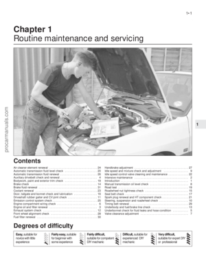 2
2 3
3 4
4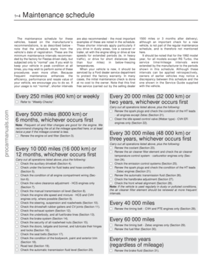 5
5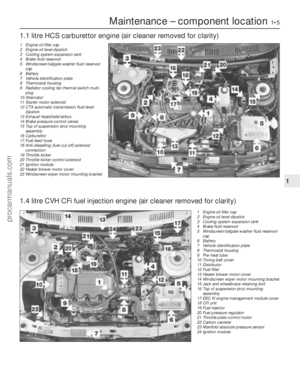 6
6 7
7 8
8 9
9 10
10 11
11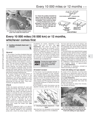 12
12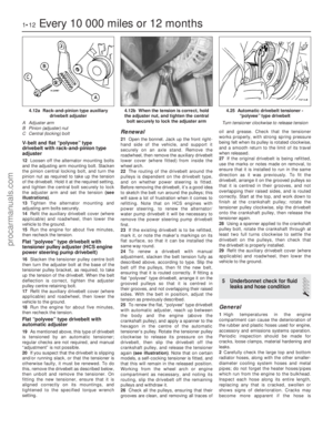 13
13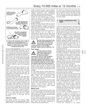 14
14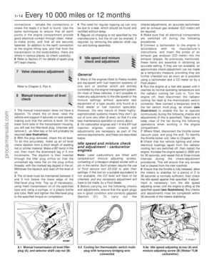 15
15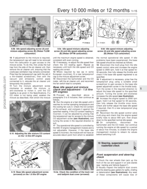 16
16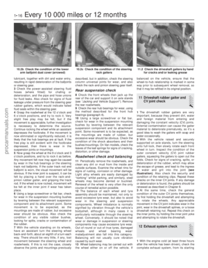 17
17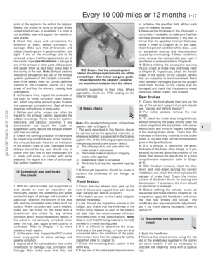 18
18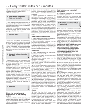 19
19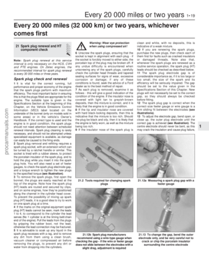 20
20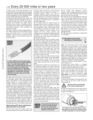 21
21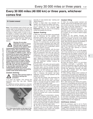 22
22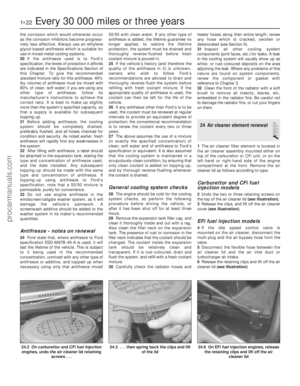 23
23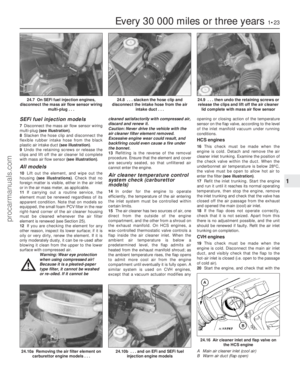 24
24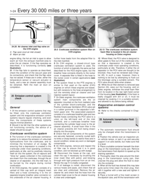 25
25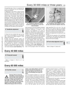 26
26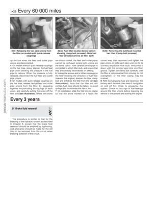 27
27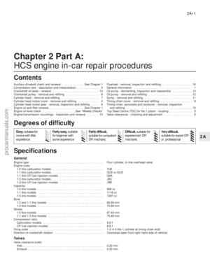 28
28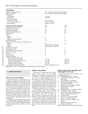 29
29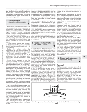 30
30 31
31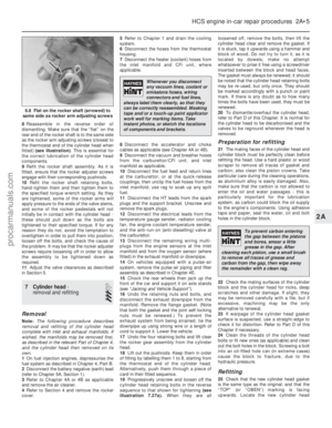 32
32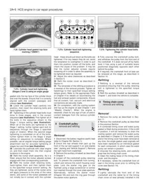 33
33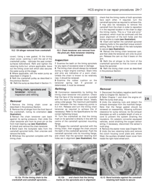 34
34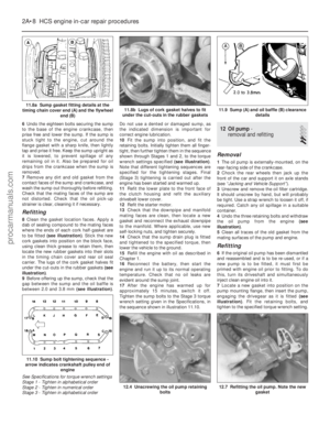 35
35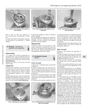 36
36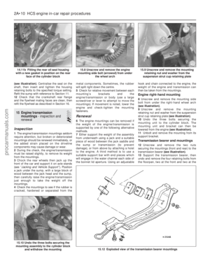 37
37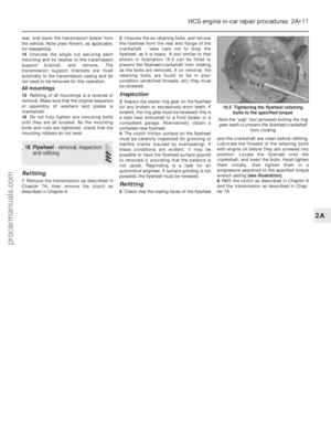 38
38 39
39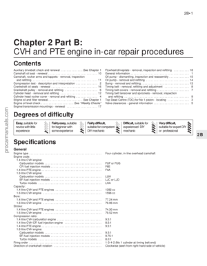 40
40 41
41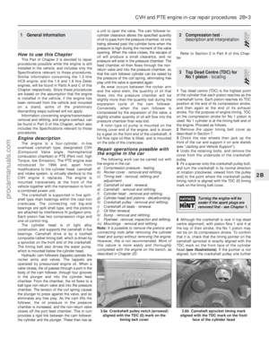 42
42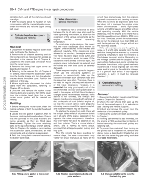 43
43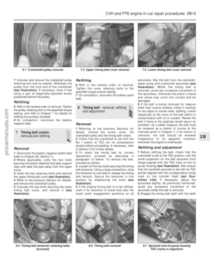 44
44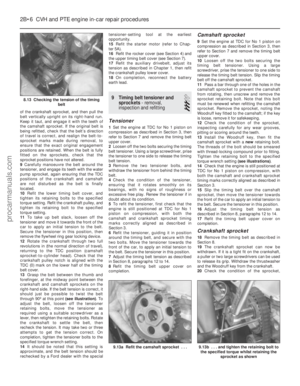 45
45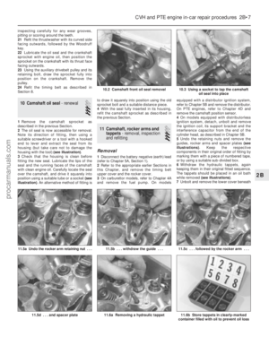 46
46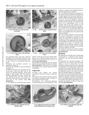 47
47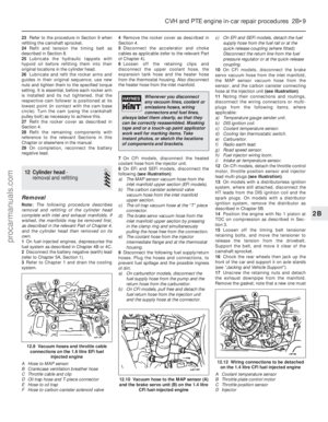 48
48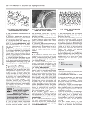 49
49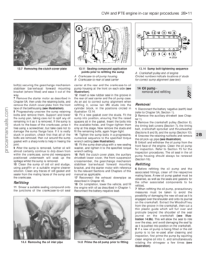 50
50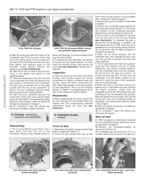 51
51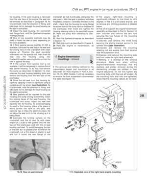 52
52 53
53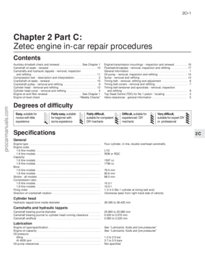 54
54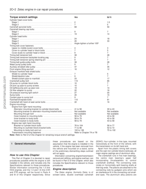 55
55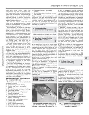 56
56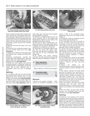 57
57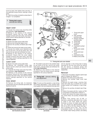 58
58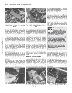 59
59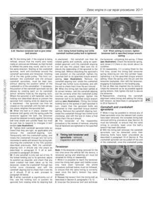 60
60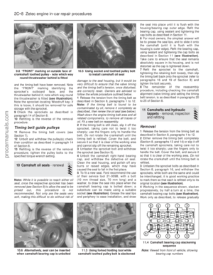 61
61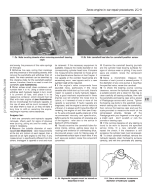 62
62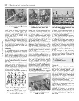 63
63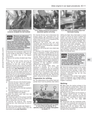 64
64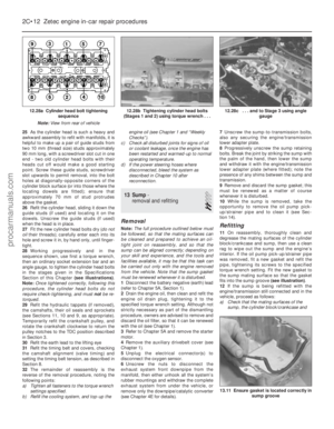 65
65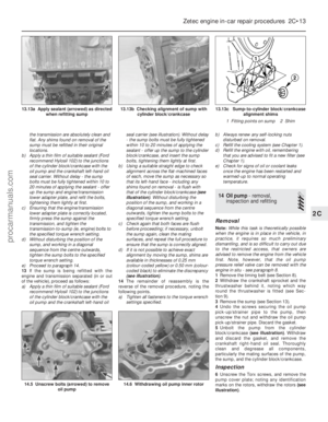 66
66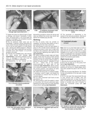 67
67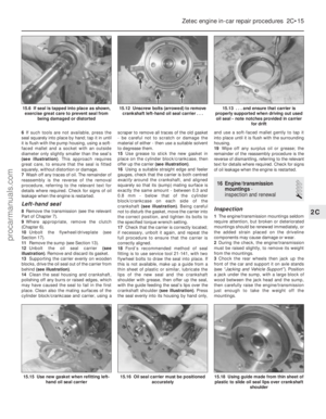 68
68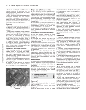 69
69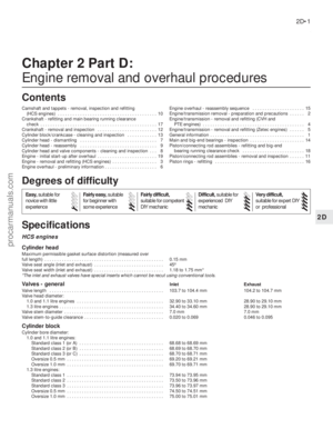 70
70 71
71 72
72 73
73 74
74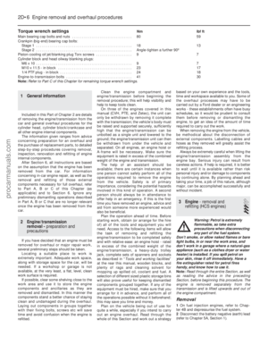 75
75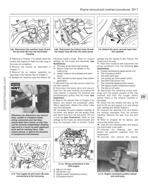 76
76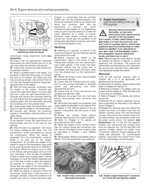 77
77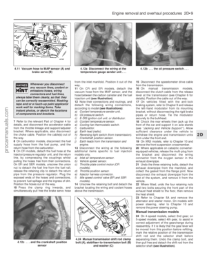 78
78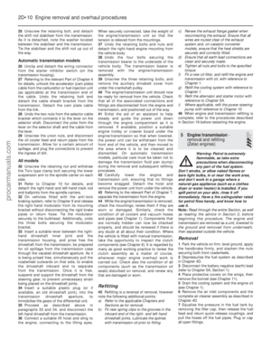 79
79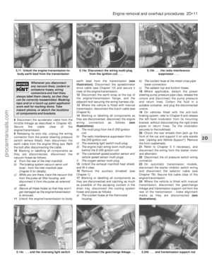 80
80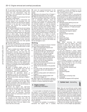 81
81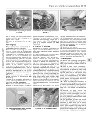 82
82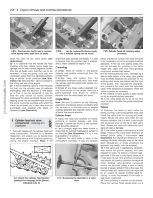 83
83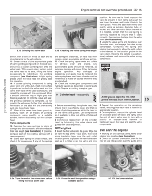 84
84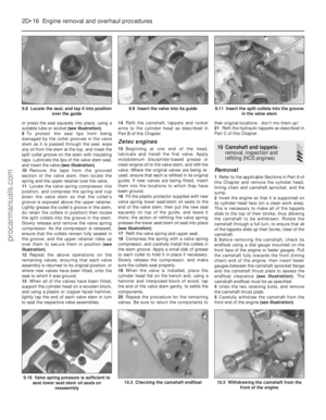 85
85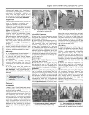 86
86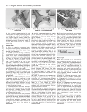 87
87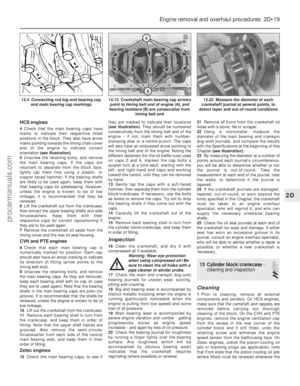 88
88 89
89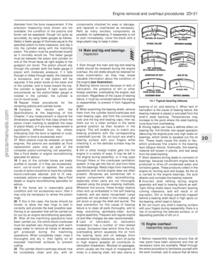 90
90 91
91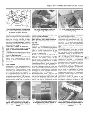 92
92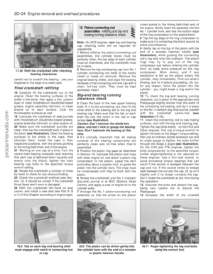 93
93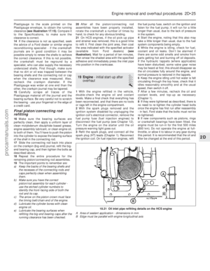 94
94 95
95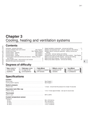 96
96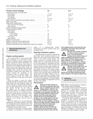 97
97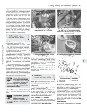 98
98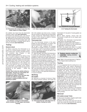 99
99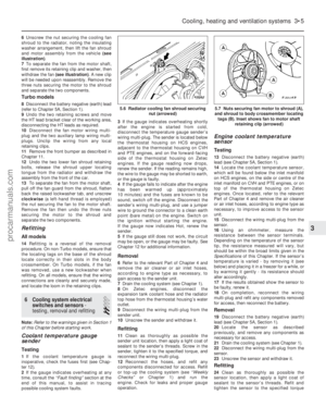 100
100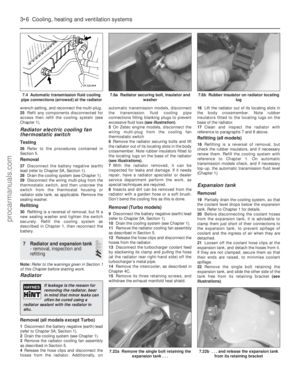 101
101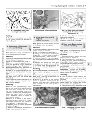 102
102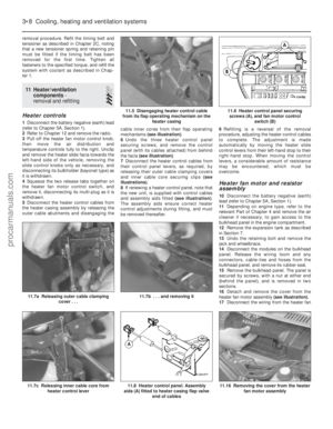 103
103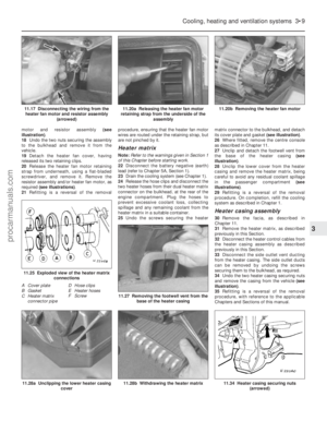 104
104 105
105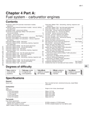 106
106 107
107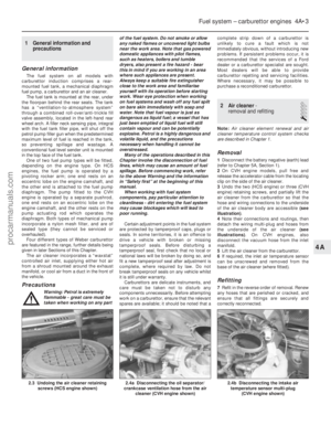 108
108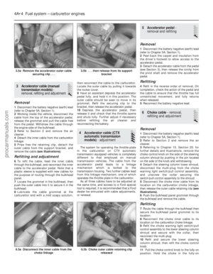 109
109 110
110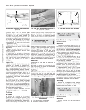 111
111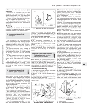 112
112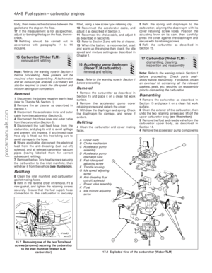 113
113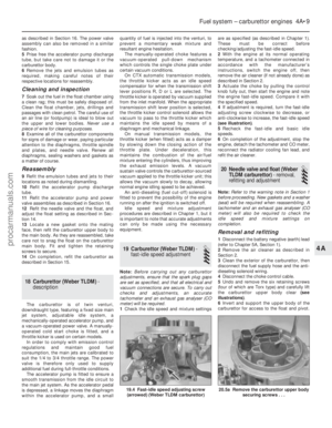 114
114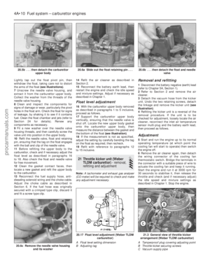 115
115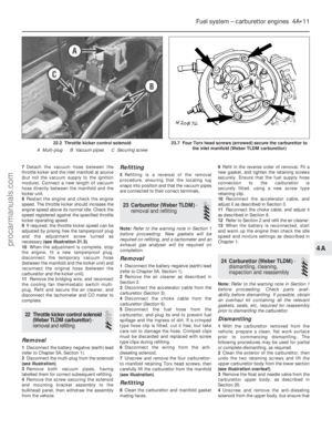 116
116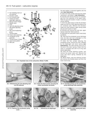 117
117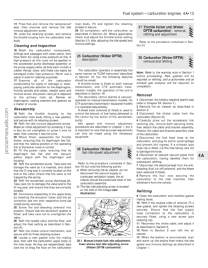 118
118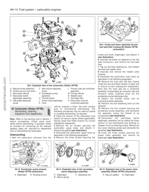 119
119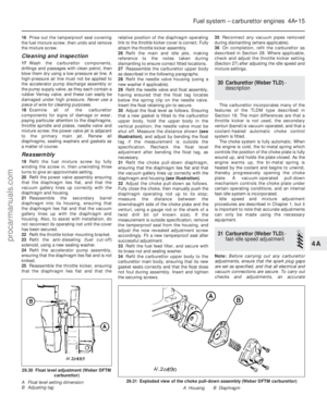 120
120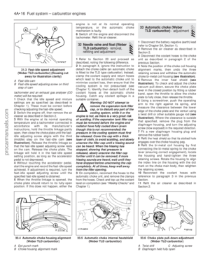 121
121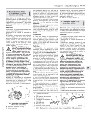 122
122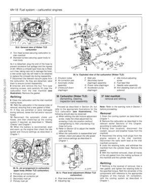 123
123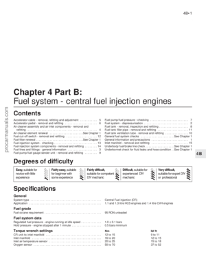 124
124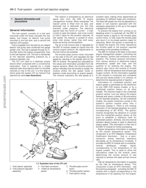 125
125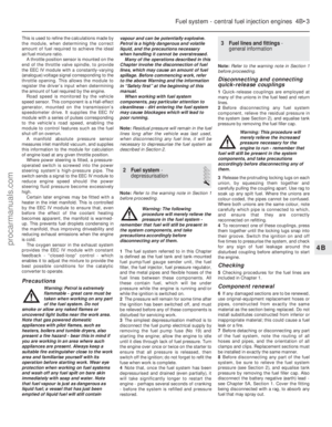 126
126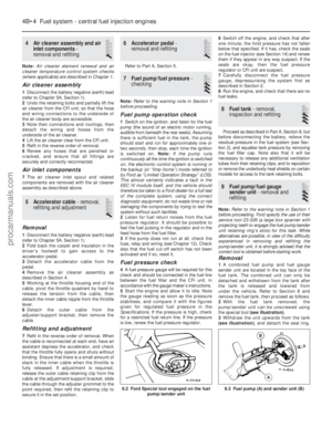 127
127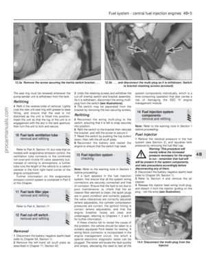 128
128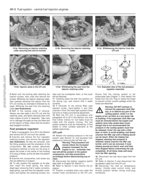 129
129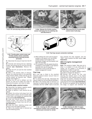 130
130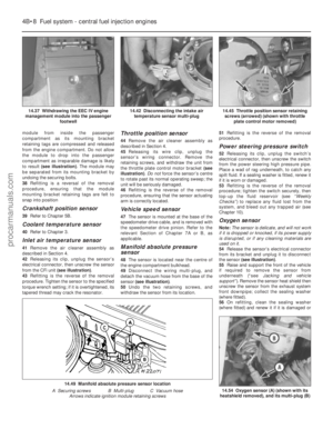 131
131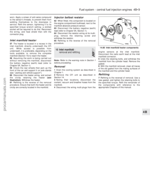 132
132 133
133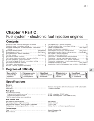 134
134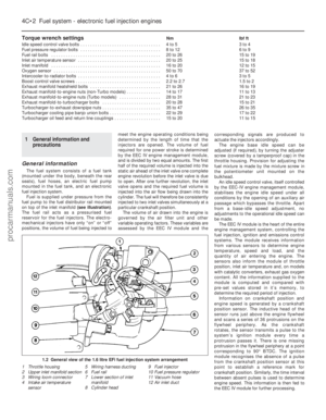 135
135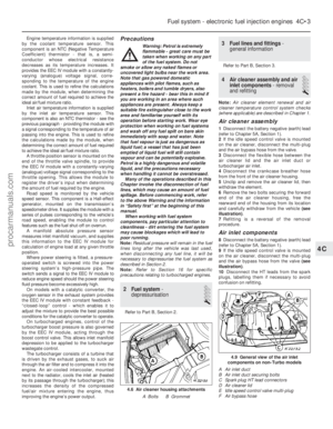 136
136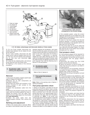 137
137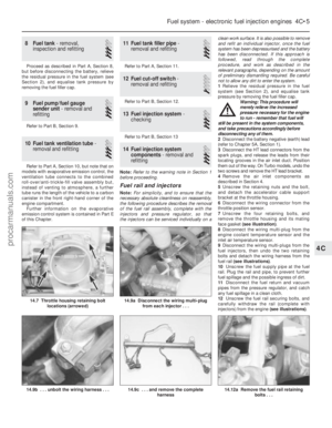 138
138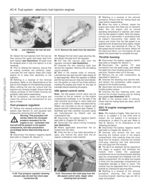 139
139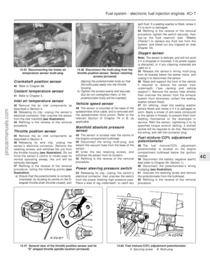 140
140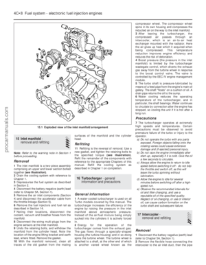 141
141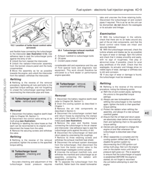 142
142 143
143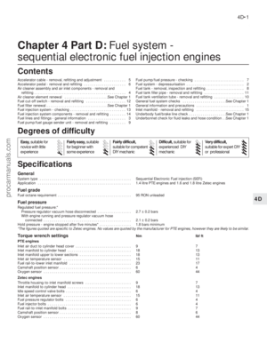 144
144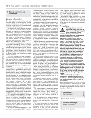 145
145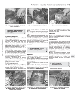 146
146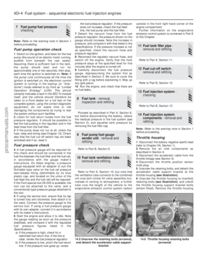 147
147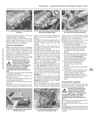 148
148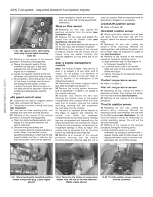 149
149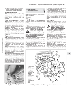 150
150 151
151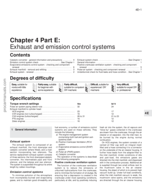 152
152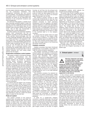 153
153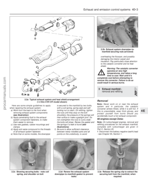 154
154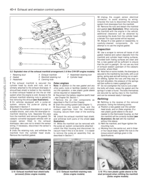 155
155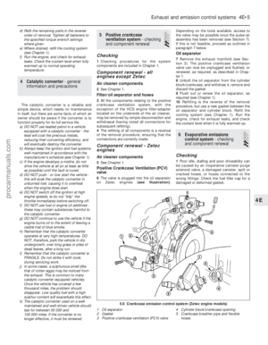 156
156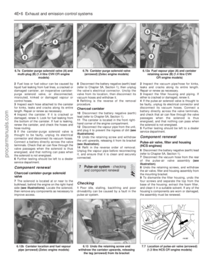 157
157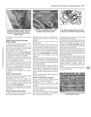 158
158 159
159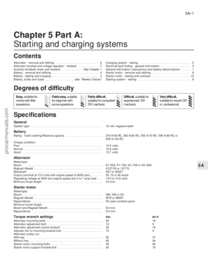 160
160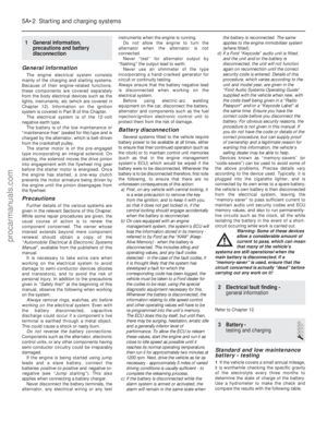 161
161 162
162 163
163 164
164 165
165 166
166 167
167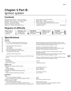 168
168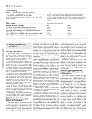 169
169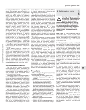 170
170 171
171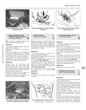 172
172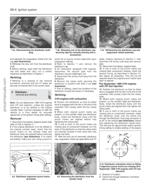 173
173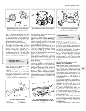 174
174 175
175 176
176 177
177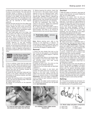 178
178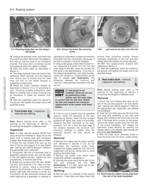 179
179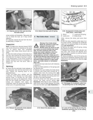 180
180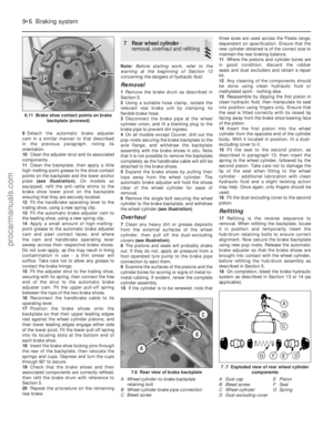 181
181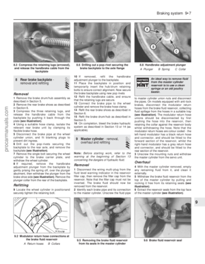 182
182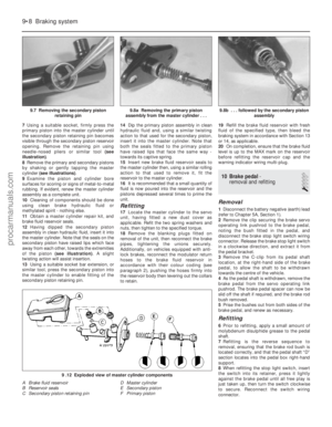 183
183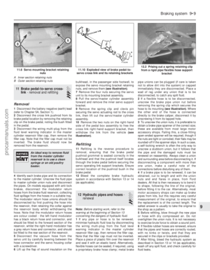 184
184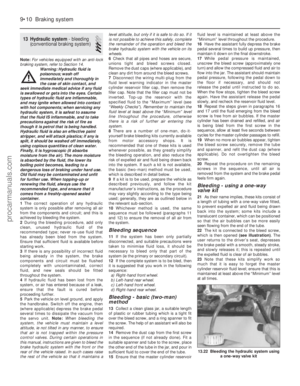 185
185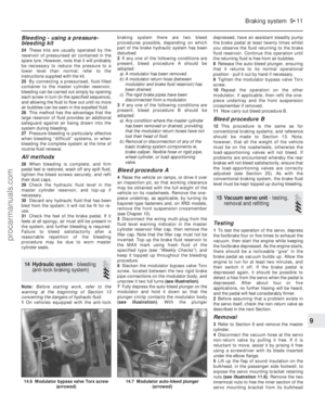 186
186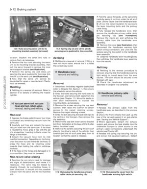 187
187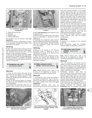 188
188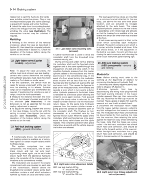 189
189 190
190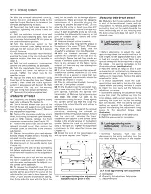 191
191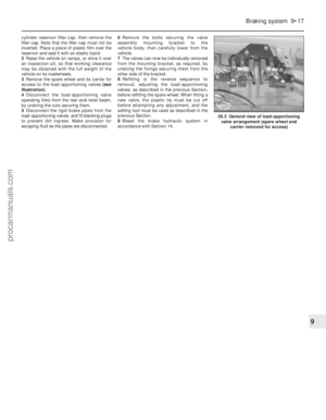 192
192 193
193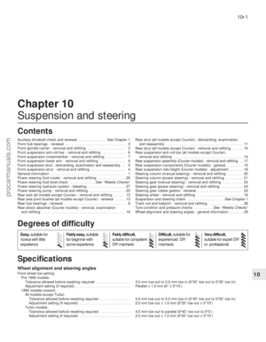 194
194 195
195 196
196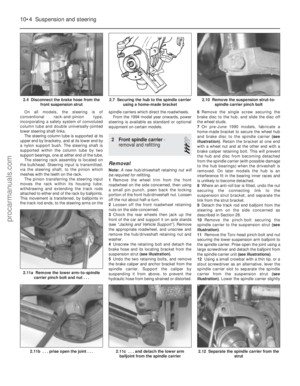 197
197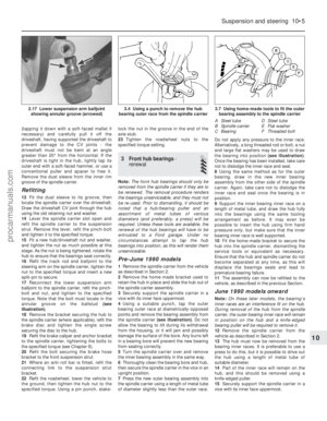 198
198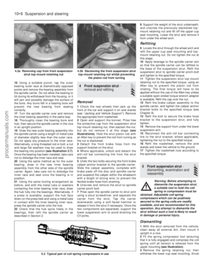 199
199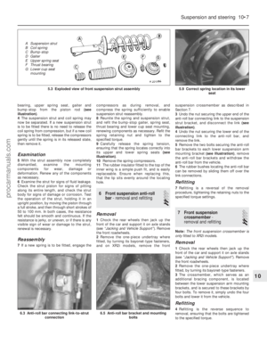 200
200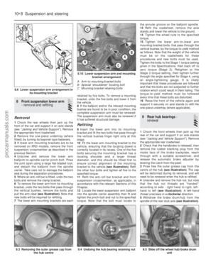 201
201 202
202 203
203 204
204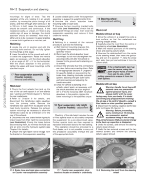 205
205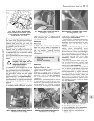 206
206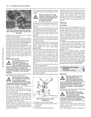 207
207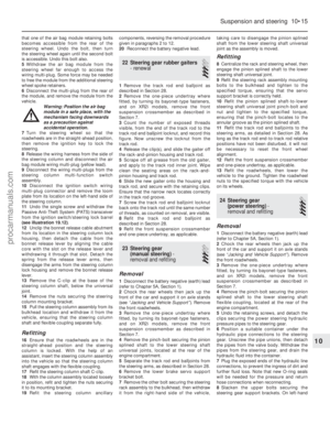 208
208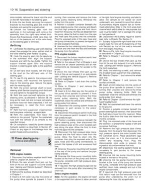 209
209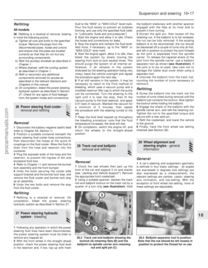 210
210 211
211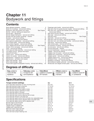 212
212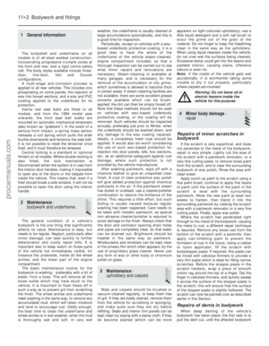 213
213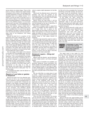 214
214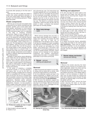 215
215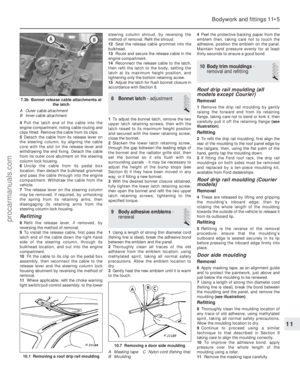 216
216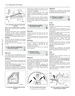 217
217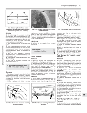 218
218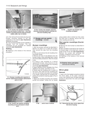 219
219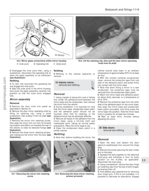 220
220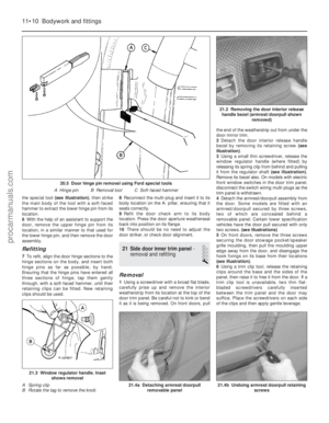 221
221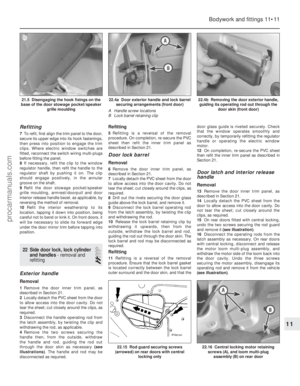 222
222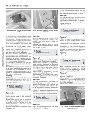 223
223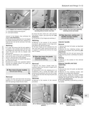 224
224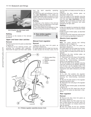 225
225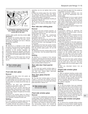 226
226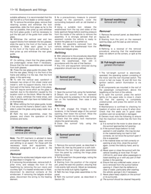 227
227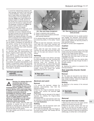 228
228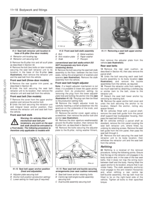 229
229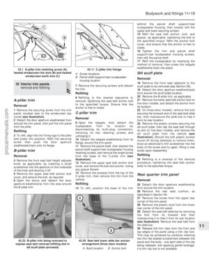 230
230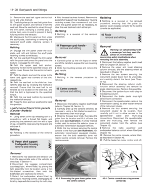 231
231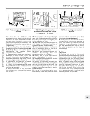 232
232 233
233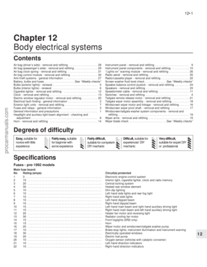 234
234 235
235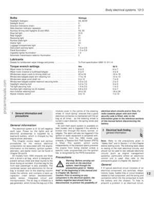 236
236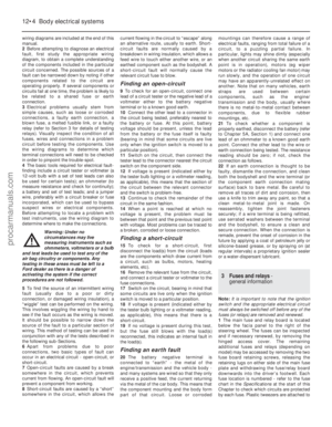 237
237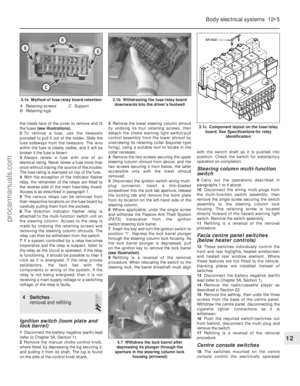 238
238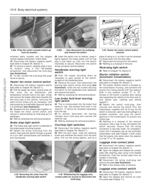 239
239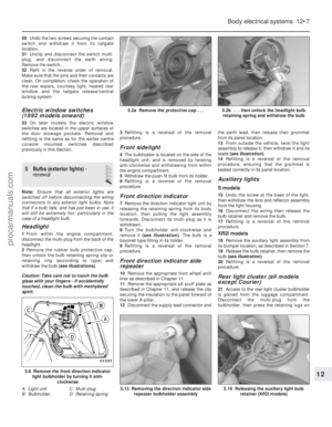 240
240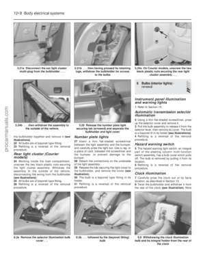 241
241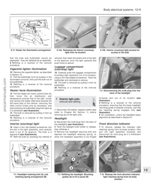 242
242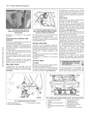 243
243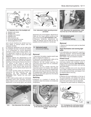 244
244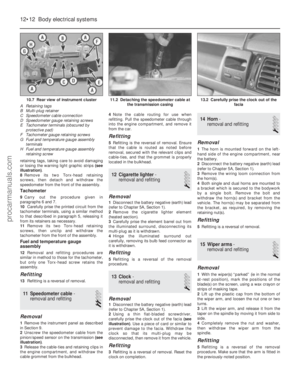 245
245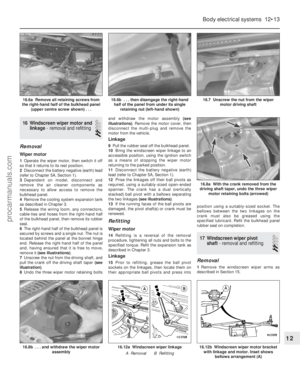 246
246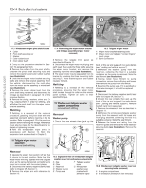 247
247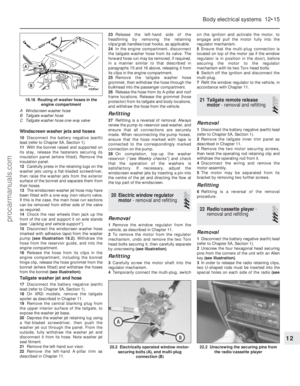 248
248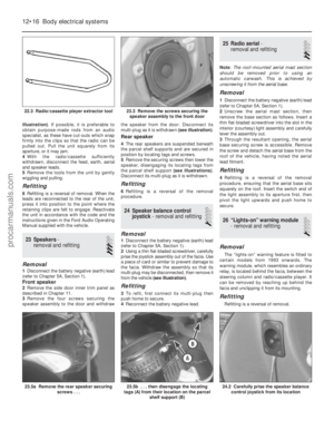 249
249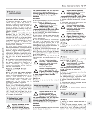 250
250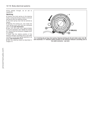 251
251 252
252 253
253 254
254 255
255 256
256 257
257 258
258 259
259 260
260 261
261 262
262 263
263 264
264 265
265 266
266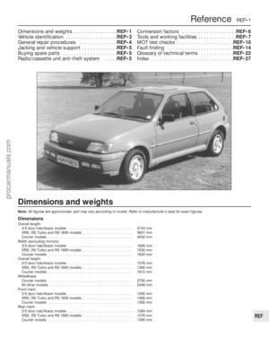 267
267 268
268 269
269 270
270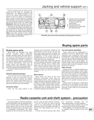 271
271 272
272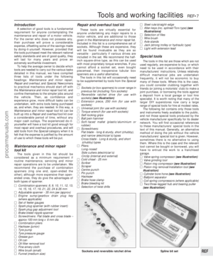 273
273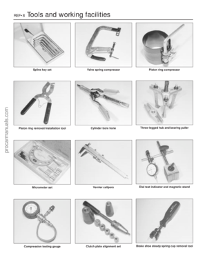 274
274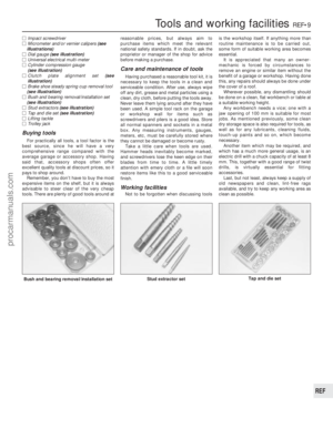 275
275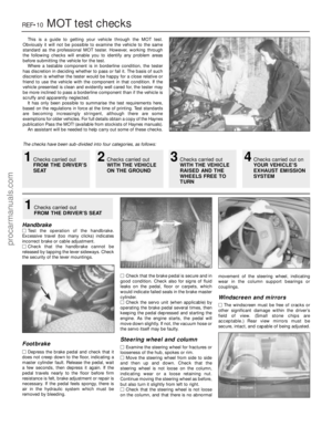 276
276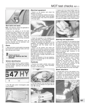 277
277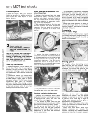 278
278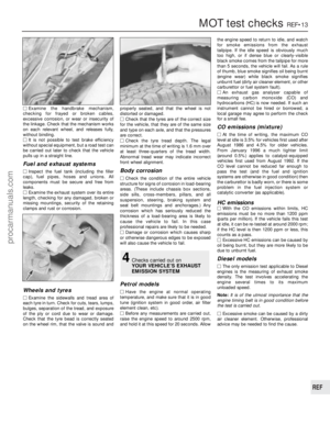 279
279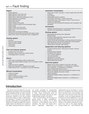 280
280 281
281 282
282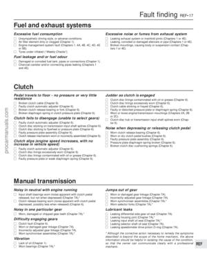 283
283 284
284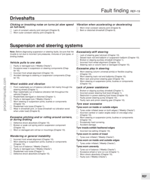 285
285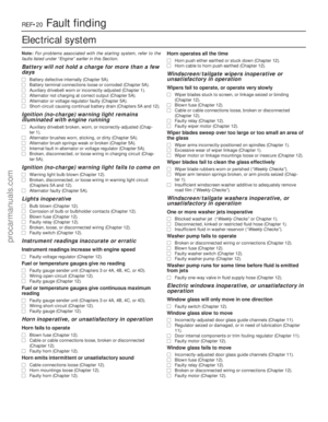 286
286 287
287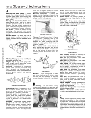 288
288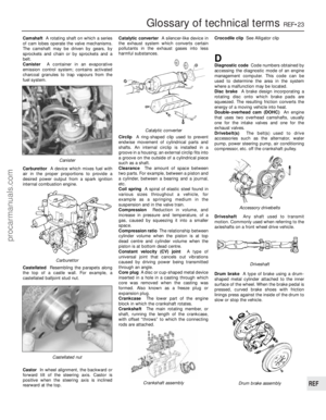 289
289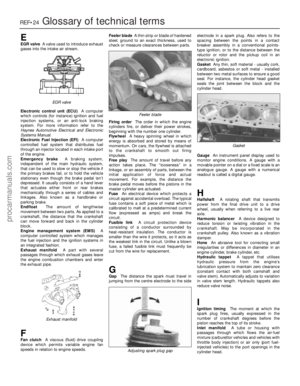 290
290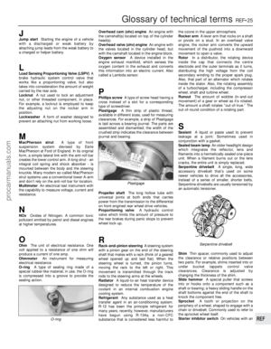 291
291 292
292 293
293 294
294 295
295