Page 17 of 296
 for chafing or
deterio")
lubricant, together with dirt and water entry,
resulting in rapid deterioration of the balljoints
or steering gear.
3Check the power-assisted steering fluid
hoses (where fitted) for chafing or
deterioration, and the pipe and hose unions
for fluid leaks. Also check for signs of fluid
leakage under pressure from the steering gear
rubber gaiters, which would indicate failed
fluid seals within the steering gear.
4 Grasp the roadwheel at the 12 o’clock and
6 o’clock positions, and try to rock it. Very
slight free play may be felt, but if the
movement is appreciable, further investigation
is necessary to determine the source.
Continue rocking the wheel while an assistant
depresses the footbrake. If the movement is
now eliminated or significantly reduced, it is
likely that the hub bearings are at fault. If the
free play is still evident with the footbrake
depressed, then there is wear in the
suspension joints or mountings.
5 Now grasp the wheel at the 9 o’clock and 3
o’clock positions, and try to rock it as before.
Any movement felt now may again be caused
by wear in the hub bearings or the steering
track rod balljoints. If the outer track rod end
balljoint is worn, the visual movement will be
obvious. If the inner joint is suspect, it can be
felt by placing a hand over the rack-and-
pinion rubber gaiter, and gripping the track
rod. If the wheel is now rocked, movement will
be felt at the inner joint if wear has taken
place.
6 Using a large screwdriver or flat bar, check
for wear in the suspension mounting bushes
by levering between the relevant suspension
component and its attachment point. Some
movement is to be expected, as the
mountings are made of rubber, but excessive
wear should be obvious. Also check the
condition of any visible rubber bushes,
looking for splits, cracks or contamination of
the rubber.
7 With the vehicle standing on its wheels,
have an assistant turn the steering wheel
back-and-forth, about an eighth of a turn each
way. There should be very little, if any, lost
movement between the steering wheel and
roadwheels. If this is not the case, closely
observe the joints and mountings previously described, but in addition, check the steering
column universal joints for wear, and also
check the rack-and-pinion steering gear itself.
Rear suspension check
8
Chock the front wheels then jack up the
rear of the car and support it on axle stands
(see “Jacking and Vehicle Support” ). Remove
the rear roadwheels.
9 Check the rear hub bearings for wear, using
the method described for the front hub
bearings (paragraph 4).
10 Using a large screwdriver or flat bar,
check for wear in the suspension mounting
bushes by levering between the relevant
suspension component and its attachment
point. Some movement is to be expected, as
the mountings are made of rubber, but
excessive wear should be obvious. Check the
condition of the shock absorbers and their
bushes/mountings. On Van models, check the
leaves of the leaf springs for signs of cracking,
distortion, or other damage.
Roadwheel check and balancing
11 Periodically remove the roadwheels, and
clean any dirt or mud from the inside and
outside surfaces. Examine the wheel rims for
signs of rusting, corrosion or other damage.
Light alloy wheels are easily damaged by
“kerbing” whilst parking, and similarly, steel
wheels may become dented or buckled.
Renewal of the wheel is very often the only
course of remedial action possible.
12 The balance of each wheel and tyre
assembly should be maintained, not only to
avoid excessive tyre wear, but also to avoid
wear in the steering and suspension
components. Wheel imbalance is normally
signified by vibration through the vehicle’s
bodyshell, although in many cases it is
particularly noticeable through the steering
wheel. Conversely, it should be noted that
wear or damage in suspension or steering
components may cause excessive tyre wear.
Out-of-round or out-of-true tyres, damaged
wheels and wheel bearing wear/
maladjustment also fall into this category.
Balancing will not usually cure vibration
caused by such wear.
13 Wheel balancing may be carried out with
the wheel either on or off the vehicle. If balanced on the vehicle, ensure that the
wheel-to-hub relationship is marked in some
way prior to subsequent wheel removal, so
that it may be refitted in its original position.
11 Driveshaft rubber gaiter and
CV joint check
1
1The driveshaft rubber gaiters are very
important, because they prevent dirt, water
and foreign material from entering and
damaging the constant velocity (CV) joints.
External contamination can cause the gaiter
material to deteriorate prematurely, so it’s a
good idea to wash the gaiters with soap and
water occasionally.
2 With the vehicle raised and securely
supported on axle stands, turn the steering
onto full-lock, then slowly rotate each front
wheel in turn. Inspect the condition of the
outer constant velocity (CV) joint rubber
gaiters, squeezing the gaiters to open out the
folds. Check for signs of cracking, splits, or
deterioration of the rubber, which may allow
the escape of grease, and lead to the ingress
of water and grit into the joint (see
illustration) . Also check the security and
condition of the retaining clips. Repeat these
checks on the inner CV joints. If any damage
or deterioration is found, the gaiters should be
renewed as described in Chapter 8.
3 At the same time, check the general
condition of the outer CV joints themselves,
by first holding the driveshaft and attempting
to rotate the wheels. Any appreciable
movement in the CV joint indicates wear in the
joint, wear in the driveshaft splines, or a loose
driveshaft retaining nut. Repeat this check on
the inner joints, by holding the inner joint yoke
and attempting to rotate the driveshaft.
12 Exhaust system check
1
1 With the engine cold (at least three hours
after the vehicle has been driven), check the
complete exhaust system, from its starting
1•16Every 10 000 miles or 12 months
11.2 Check the driveshaft gaiters by hand for cracks and/or leaking grease10.2c Check the condition of the steering rack gaiters10.2b Check the condition of the lowerarm balljoint dust cover (arrowed)
1595Ford Fiesta Remakeprocarmanuals.com
http://vnx.su
Page 18 of 296

point at the engine to the end of the tailpipe.
Ideally, this should be done on a hoist, where
unrestricted access is available; if a hoist is
not available, raise and support the vehicle on
axle stands.
2Check the pipes and connections for
evidence of leaks, severe corrosion, or
damage. Make sure that all brackets and
rubber mountings are in good condition, and
tight; if any of the mountings are to be
renewed, ensure that the replacements are of
the correct type (see illustration) . Leakage at
any of the joints or in other parts of the system
will usually show up as a black sooty stain in
the vicinity of the leak. Note: Exhaust sealants
should not be used on any part of the exhaust
system upstream of the catalytic converter -
even if the sealant does not contain additives
harmful to the converter, pieces of it may
break off and foul the element, causing local
overheating.
3 At the same time, inspect the underside of
the body for holes, corrosion, open seams,
etc, which may allow exhaust gases to enter
the passenger compartment. Seal all body
openings with silicone or body putty.
4 Rattles and other noises can often be
traced to the exhaust system, especially the
rubber mountings. Try to move the system,
silencer(s) and catalytic converter. If any
components can touch the body or
suspension parts, secure the exhaust system
with new mountings.
5 Check the running condition of the engine
by inspecting inside the end of the tailpipe;
the exhaust deposits here are an indication
of the engine’s state of tune. The inside of the
tailpipe should be dry, and should vary in
colour from dark grey to light grey/brown; if it
is black and sooty, or coated with white
deposits, the engine is in need of a thorough
fuel system inspection.
13 Underbody and fuel/brake line check
1
1With the vehicle raised and supported on
axle stands or over an inspection pit,
thoroughly inspect the underbody and wheel
arches for signs of damage and corrosion. In
particular, examine the bottom of the side
sills, and any concealed areas where mud can
collect. Where corrosion and rust is evident,
press and tap firmly on the panel with a
screwdriver, and check for any serious
corrosion which would necessitate repairs. If
the panel is not seriously corroded, clean
away the rust, and apply a new coating of
underseal. Refer to Chapter 11 for more
details of body repairs.
2 At the same time, inspect the PVC-coated
lower body panels for stone damage and
general condition.
3 Inspect all of the fuel and brake lines on the
underbody for damage, rust, corrosion and
leakage. Also make sure that they are correctly supported in their clips. Where
applicable, check the PVC coating on the
lines for damage.
14 Brake check
2
Note:
For detailed photographs of the brake
system, refer to Chapter 9.
1 The work described in this Section should
be carried out at the specified intervals, or
whenever a defect is suspected in the braking
system. Any of the following symptoms could
indicate a potential brake system defect:
a) The vehicle pulls to one side when the brake pedal is depressed.
b) The brakes make scraping or dragging
noises when applied.
c) Brake pedal travel is excessive.
d) The brake fluid requires repeated topping-
up.
2 A thorough inspection should be made to
confirm the thickness of the linings, as
follows.
Front brakes
3 Chock the rear wheels then jack up the
front of the car and support it on axle stands
(see “Jacking and Vehicle Support” ).
4 For better access to the brake calipers,
remove the wheels.
5 Look through the inspection window in the
caliper, and check that the thickness of the
friction lining material on each of the pads is
not less than the recommended minimum
thickness given in the Specifications. Note:
Bear in mind that the lining material is normally
bonded to a metal backing plate.
6 If it is difficult to determine the exact
thickness of the pad linings, or if you are at all
concerned about the condition of the pads,
then remove them from the calipers for further
inspection (refer to Chapter 9).
7 Check the remaining brake caliper in the
same way.
8 If any one of the brake pads has worn down to, or below, the specified limit,
all fourpads
must be renewed as a set.
9 Measure the thickness of the discs with a
micrometer, if available, to make sure that they
still have service life remaining. If any disc is
thinner than the specified minimum thickness,
renew it (refer to Chapter 9). In any case,
check the general condition of the discs. Look
for excessive scoring and discolouration
caused by overheating. If these conditions
exist, remove the relevant disc and have it
resurfaced or renewed (refer to Chapter 9).
10 Before refitting the wheels and lowering
the car, check all brake lines and hoses (refer
to Chapter 9). In particular, check the flexible
hoses in the vicinity of the calipers, where
they are subjected to most movement. Bend
them between the fingers (but do not actually
bend them double, or the casing may be
damaged) and check that this does not reveal
previously-hidden cracks, cuts or splits.
Rear brakes
11 Chock the front wheels then jack up the
rear of the car and support it on axle stands
(see “Jacking and Vehicle Support” ).
12 For better access, remove the rear
wheels.
13 To check the brake shoe lining thickness
without removing the brake drums, prise the
rubber plugs from the backplates, and use an
electric torch and mirror to inspect the linings
of the leading brake shoes. Check that the
thickness of the lining material on the brake
shoes is not less than the recommendation
given in the Specifications.
14 If it is difficult to determine the exact
thickness of the brake shoe linings, or if you
are at all concerned about the condition of the
shoes, then remove the rear drums for a more
comprehensive inspection (refer to Chap-
ter 9).
15 With the drum removed, check the shoe
return and hold-down springs for correct
installation, and check the wheel cylinders for
leakage of brake fluid. Check the friction
surface of the brake drums for scoring and
discoloration. If excessive, the drum should
be resurfaced or renewed.
16 Before refitting the wheels, check all
brake lines and hoses (refer to Chapter 9). On
completion, apply the handbrake and check
that the rear wheels are locked. The
handbrake also requires periodic adjustment,
and if its travel seems excessive, refer to
Section 27.
15 Roadwheel nut tightness check
1
1Apply the handbrake.
2 Remove the wheel covers, using the flat
end of the wheelbrace supplied in the tool kit
(on some models it will be necessary to
unscrew the retaining bolts with a special
key).
Every 10 000 miles or 12 months1•17
12.2 Ensure that the exhaust system
rubber mountings replacements are of the correct type - their colour is a good guide. Those nearest to the catalytic converterare more heat-resistant than the others
1
1595Ford Fiesta Remakeprocarmanuals.com
http://vnx.su
Page 19 of 296

3Check that the roadwheel nuts are tightened
to the specified torque wrench setting.
4 Refit the wheel covers.
16 Door, tailgate and bonnet
check and lubrication
1
1Check that the doors and tailgate/boot lid
close securely. Check that the bonnet safety
catch operates correctly. Check the operation
of the door check straps.
2 Lubricate the hinges, door check straps,
the striker plates and the bonnet catch
sparingly with a little oil or grease.
17 Seat belt check
1
1 Check the seat belts for satisfactory
operation and condition. Inspect the webbing
for fraying and cuts. Check that they retract
smoothly and without binding into their reels.
2 Check that the seat belt mounting bolts are
tight, and if necessary tighten them to the
specified torque wrench settings as given in
Chapter 11.
18 Bodywork, paint and exterior trim check
1
1The best time to carry out this check is after
the car has been washed so that any surface
blemish or scratch will be clearly evident and
not hidden by a film of dirt.
2 Starting at one front corner check the
paintwork all around the car, looking for minor
scratches or more serious dents. Check all
the trim and make sure that it is securely
attached over its entire length.
3 Check the security of all door locks, door
mirrors, badges, bumpers, front grille and
wheel trim. Anything found loose, or in need of
further attention should be done with reference
to the relevant Chapters of this manual.
4 Rectify any problems noticed with the
paintwork or body panels as described in
Chapter 11.
19 Road test
1
Check the operation and
performance of the braking
system
1 Make sure that the vehicle does not pull to
one side when braking, and that the wheels
do not lock prematurely when braking hard.
2 Check that there is no vibration through the
steering when braking. 3
Check that the handbrake operates
correctly, without excessive movement of the
lever, and that it holds the vehicle stationary
on a slope.
4 Test the operation of the brake servo unit
as follows. With the engine switched off,
depress the footbrake four or five times to
exhaust the vacuum, then hold the pedal
depressed. Start the engine, and there should
be a noticeable “give” in the brake pedal as
vacuum builds up. Allow the engine to run for
at least two minutes, and then switch it off. If
the brake pedal is depressed again, it should
be possible to detect a hiss from the servo as
the pedal is depressed. After about four or five
applications, no further hissing should be
heard, and the pedal should feel considerably
firmer.
Steering and suspension
5 Check for any abnormalities in the steering,
suspension, handling or road “feel”.
6 Drive the vehicle, and check that there are
no unusual vibrations or noises.
7 Check that the steering feels positive, with
no excessive sloppiness or roughness, and
check for any suspension noises when
cornering and driving over bumps.
Drivetrain
8 Check the performance of the engine,
transmission and driveshafts.
9 Check that the engine starts correctly, both
when cold and when hot.
10 Listen for any unusual noises from the
engine and transmission.
11 Make sure that the engine runs smoothly
when idling, and that there is no hesitation
when accelerating.
12 On manual transmission models, check
that all gears can be engaged smoothly
without noise, and that the gear lever action is
not abnormally vague or “notchy”.
13 On automatic transmission models, make
sure that the drive seems smooth without
jerks or engine speed “flare-ups”. Check that
all the gear positions can be selected with the
vehicle at rest. If any problems are found, they
should be referred to a Ford dealer.
14 Listen for a metallic clicking sound from
the front of the vehicle, as the vehicle is driven
slowly in a circle with the steering on full-lock.
Carry out this check in both directions. If a
clicking noise is heard, this indicates wear in a
driveshaft joint, in which case renew the joint
if necessary.
Clutch
15 Check that the clutch pedal moves
smoothly and easily through its full travel, and
that the clutch itself functions correctly, with
no trace of slip or drag. If the movement is
uneven or stiff in places, check that the cable
is routed correctly, with no sharp turns.
16 Inspect both ends of the clutch inner
cable, both at the transmission end and inside
the car, for signs of wear and fraying.
Instruments and electrical
equipment
17 Check the operation of all instruments
and electrical equipment.
18 Make sure that all instruments read
correctly, and switch on all electrical equipment
in turn, to check that it functions properly.
20 Automatic transmission fluid level check
1
1The level of the automatic transmission fluid
should be carefully maintained. Low fluid level
can lead to slipping or loss of drive, while
overfilling can cause foaming, loss of fluid and
transmission damage.
2 The transmission fluid level should only be
checked when the transmission is hot (at its
normal operating temperature). If the vehicle
has just been driven over 10 miles (15 miles in
a cold climate), and the fluid temperature is 60
to 70ºC, the transmission is hot.
Caution: If the vehicle has just been driven
for a long time at high speed or in city
traffic in hot weather, or if it has been
pulling a trailer, an accurate fluid level
reading cannot be obtained. In these
circumstances, allow the fluid to cool
down for about 30 minutes.
3 Park the vehicle on level ground, apply the
handbrake, and start the engine. While the
engine is idling, depress the brake pedal and
move the selector lever through all the gear
positions three times, beginning and ending in
“P”.
4 Allow the engine to idle for one minute, then
(with the engine still idling) remove the
dipstick from its tube. Note the condition and
colour of the fluid on the dipstick.
5 Wipe the fluid from the dipstick with a clean
rag, and re-insert it into the filler tube until the
cap seats.
6 Pull the dipstick out again, and note the
fluid level. The level should be between
the “MIN” and “MAX” marks. If the level is
on the “MIN” mark, stop the engine, and add
the specified automatic transmission fluid
through the dipstick tube, using a clean funnel
if necessary. It is important not to introduce
dirt into the transmission when topping-up.
7 Add the fluid a little at a time, and keep
checking the level as previously described
until it is correct. The difference between the
“MIN” and “MAX” marks on the dipstick is
approximately 0.4 litres.
8 The need for regular topping-up of the
transmission fluid indicates a leak, which
should be found and rectified without delay.
9 The condition of the fluid should also be
checked along with the level. If the fluid on the
dipstick is black or a dark reddish-brown
colour, or if it has a burned smell, the fluid
should be changed. If you are in doubt about
the condition of the fluid, purchase some new
fluid, and compare the two for colour and smell.
1•18Every 10 000 miles or 12 months
1595Ford Fiesta Remakeprocarmanuals.com
http://vnx.su
Page 20 of 296

21 Spark plug renewal and HTcomponent check
1
Note: Spark plug renewal at this service
interval is only necessary on the HCS, CVH
and PTE engines. On Zetec engines, the
recommended interval for spark plug renewal
is every 30 000 miles or three years.
Spark plug check and renewal
1 It is vital for the correct running, full
performance and proper economy of the engine
that the spark plugs perform with maximum
efficiency. The most important factor in ensuring
this is that the plugs fitted are appropriate for the
engine. The suitable type is given in the
Specifications Section at the beginning of this
Chapter, on the Vehicle Emissions Control
Information (VECI) label located on the
underside of the bonnet (only on models sold in
some areas) or in the vehicle’s Owner’s
Handbook. If the correct type is used and the
engine is in good condition, the spark plugs
should not need attention between scheduled
renewal intervals. Spark plug cleaning is rarely
necessary, and should not be attempted unless
specialised equipment is available, as damage
can easily be caused to the firing ends.
2 Spark plug removal and refitting requires a
spark plug socket, with an extension which can
be turned by a ratchet handle or similar. This
socket is lined with a rubber sleeve, to protect
the porcelain insulator of the spark plug, and to
hold the plug while you insert it into the spark
plug hole. You will also need a set of feeler
gauges, to check the spark plug electrode gap,
and a torque wrench to tighten the new plugs
to the specified torque (see illustration).
3 To remove the spark plugs, first open the
bonnet; the plugs are easily reached at the
top of the engine. Note how the spark plug
(HT) leads are routed and secured by clips,
and on some engines, how they’re positioned
along the channel in the cylinder head cover.
To prevent the possibility of mixing up spark
plug (HT) leads, it is a good idea to try to work
on one spark plug at a time.
4 If the marks on the original-equipment spark
plug (HT) leads cannot be seen, mark the leads
1 to 4, to correspond to the cylinder the lead
serves (No 1 cylinder is at the timing belt/chain
end of the engine). Pull the leads from the plugs
by gripping the rubber boot, not the lead,
otherwise the lead connection may be fractured.
5 It is advisable to soak up any liquid in the
spark plug recesses with a rag, and to remove
any dirt from them using a clean brush,
vacuum cleaner or compressed air before
removing the plugs, to prevent any dirt or
water from dropping into the cylinders. Warning: Wear eye protection
when using compressed air!
6 Unscrew the spark plugs, ensuring that the
socket is kept in alignment with each plug - if
the socket is forcibly moved to either side, the
porcelain top of the plug may be broken off. If
any undue difficulty is encountered when
unscrewing any of the spark plugs, carefully
check the cylinder head threads and tapered
sealing surfaces for signs of wear, excessive
corrosion or damage; if any of these
conditions is found, seek the advice of a Ford
dealer as to the best method of repair.
7 As each plug is removed, examine it as
follows - this will give a good indication of the
condition of the engine. If the insulator nose is
covered with light tan to greyish-brown
deposits, then the mixture is correct, and it is
likely that the engine is in good condition.
8 If the tip and insulator nose are covered
with hard black-looking deposits, then this is
indicative that the mixture is too rich. Should
the plug be black and oily, then it is likely that
the engine is fairly worn, as well as the mixture
being too rich.
9 If the insulator nose of the spark plug is clean and white, with no deposits, this is
indicative of a weak mixture.
10
If you are renewing the spark plugs,
purchase the new plugs, then check each of
them first for faults such as cracked insulators
or damaged threads. Note also that,
whenever the spark plugs are renewed as a
routine service operation, the spark plug (HT)
leads should be checked as described below.
11 The spark plug electrode gap is of
considerable importance as, if it is too large or
too small, the size of the spark and its
efficiency will be seriously impaired. The gap
should be set to the value given in the
Specifications Section of this Chapter. New
plugs will not necessarily be set to the correct
gap, so they should always be checked
before fitting.
12 The spark plug gap is correct when the
correct-size feeler gauge or wire gauge is a
firm sliding fit between the electrodes (see
illustrations) .
13 To adjust the electrode gap, bend open, or
close up, the outer plug electrode until the
correct gap is achieved (see illustration). The
centre electrode should never be bent, as this
may crack the insulation and cause plug failure,
Every 20 000 miles (32 000 km) or two years, whichever
comes first
Every 20 000 miles or two years1•19
21.12b Spark plug manufacturers
recommend using a wire-type gauge when
checking the gap - if the wire or feeler gauge
does not slide between the electrodes with a slight drag, adjustment is required
21.12a Measuring a spark plug gap with a feeler gauge21.2 Tools required for changing spark plugs
21.13 To change the gap, bend the outer
electrode only, and be very careful not to crack or chip the porcelain insulator
surrounding the centre electrode
1
1595Ford Fiesta Remakeprocarmanuals.com
http://vnx.su
Page 21 of 296

if nothing worse. If the outer electrode is not
exactly over the centre electrode, bend it gently
to align them. Special spark plug gap adjusting
tools are available from motor accessory shops,
or from certain spark plug manufacturers.
14Before fitting the spark plugs, check that
the threaded connector sleeves at the top of
the plugs are tight, and that the plug exterior
surfaces and threads are clean. Brown
staining on the porcelain, immediately above
the metal body, is quite normal, and does not
necessarily indicate a “leak” between the
body and insulator.
15 Apply a smear of copper-based grease or
anti-seize compound to the threads of each
plug, and screw them in by hand where
possible. Take extra care to enter the plug
threads correctly, as the cylinder head is of
aluminium alloy.
16 When each spark plug is started correctly
on its threads, screw it down until it just seats
lightly, then tighten it to the specified torque
wrench setting. If a torque wrench is not
available - and this is one case where the use of
a torque wrench is strongly recommended -
tighten each spark plug through no more than
1/4 of a turn (CVH and PTE engines) or 1/16 of a
turn (HCS and Zetec engines) after it seats. HCS
and Zetec engines are fitted with taper-seat
spark plugs, identifiable by not having a sealing
washer, and these in particular should NEVER
be overtightened - their tapered seats mean
they are almost impossible to remove if abused.
17 Reconnect the spark plug (HT) leads in
their correct order, using a twisting motion on
the boot until it is firmly seated on the end of
the spark plug and on the cylinder head cover.
Spark plug (HT) lead, distributor
cap and rotor arm check
18 The spark plug (HT) leads should be
checked whenever the plugs themselves are renewed. Start by making a visual check of
the leads while the engine is running. In a
darkened garage (make sure there is
ventilation) start the engine and observe each
lead. Be careful not to come into contact with
any moving engine parts. If there is a break in
the lead, you will see arcing or a small spark
at the damaged area.
19
The spark plug (HT) leads should be
inspected one at a time, to prevent mixing up
the firing order, which is essential for proper
engine operation. Each original lead should
be numbered to identify its cylinder. If the
number is illegible, a piece of tape can be
marked with the correct number, and
wrapped around the lead (the leads should be
numbered 1 to 4, with No 1 lead nearest the
timing belt end of the engine). The lead can
then be disconnected.
20 Check inside the boot for corrosion, which
will look like a white crusty powder. Clean this
off as much as possible; if it is excessive, or if
cleaning leaves the metal connector too badly
eroded to be fit for further use, the lead must
be renewed. Push the lead and boot back
onto the end of the spark plug. The boot
should fit tightly onto the end of the plug - if it
doesn’t, remove the lead and use pliers
carefully to crimp the metal connector inside
the boot until the fit is snug.
21 Using a clean rag, wipe the entire length
of the lead to remove built-up dirt and grease. Once the lead is clean, check for burns,
cracks and other damage. Do not bend the
lead sharply, because the conductor might
break.
22 Disconnect the lead from the ignition coil
by pressing together the plastic retaining
catches (where fitted) and pulling the end
fitting off the coil terminal. Check for corrosion
and for a tight fit. If a meter with the correct
measuring range is available, measure the
resistance of the disconnected lead from its
coil connector to its spark plug connector. If
the resistance recorded for any of the leads
exceeds the value specified, all the leads
should be renewed as a set. Refit the lead to
the coil, noting that each coil terminal is
marked with its respective cylinder number,
so that there is no risk of mixing up the leads
and upsetting the firing order.
23 Inspect the remaining spark plug (HT)
leads, ensuring that each is securely fastened
at the distributor cap or ignition coil and spark
plug when the check is complete. If any sign
of arcing, severe connector corrosion, burns,
cracks or other damage is noticed, obtain new
spark plug (HT) leads, renewing them as a set.
If new spark plug leads are to be fitted,
remove and refit them one at a time, to avoid
mix-ups in the firing order. 24
On models with distributor ignition
systems, refer to Chapter 5B and remove the
distributor cap then thoroughly clean it inside
and out with a dry lint-free rag.
25 Examine the HT lead segments inside the
cap. If they appear badly burned or pitted
renew the cap. Also check the carbon brush
in the centre of the cap, ensuring that it is free
to move and stands proud of its holder. Make
sure that there are no sign of cracks or black
“tracking” lines running down the inside of the
cap, which will also mean renewal if evident.
26 Inspect the rotor arm checking it for
security and also for signs of deterioration as
described above.
27 Refit the cap as described in Chapter 5B
on completion.
22 Idle speed control valve cleaning and maintenance
1
Note: The idle speed control valve may be
mounted on the air cleaner, on the engine
compartment bulkhead, or on the side of the inlet
manifold according to valve make and year of
manufacture. Valves manufactured by Weber are
mounted on the air cleaner and only these valves
require the periodic maintenance described
below. Bulkhead and inlet manifold mounted
valves are manufactured by Hitachi and are
maintenance free. Refer to the warning note in
Section 1 of Chapter 4C before proceeding.
1 Remove the valve as described in Chap-
ter 4C, Section 14.
2 Immerse the valve head in a suitable
container filled with clean petrol, and allow it
to soak for approximately three minutes.
3 Clean the valve bore, slots and piston with
petrol, using a suitable lint-free cloth, then
gently move the piston up and down in its
bore using a small screwdriver (see
illustration) . Ensure that no cloth particles
enter the bore, and do not use the slots to
move the piston.
4 Rinse the valve again with clean petrol, then
dry it using an air line (or other source of
compressed air).
Warning: Wear eye protection
when using compressed air!
5 Clean the mating faces of the valve and the
air filter housing then refit as described in
Chapter 4C, Section 14.
1•20Every 20 000 miles or two years
22.3 Gently move the idle speed control
valve piston up and down in its bore using
a small screwdriver (1.6 litre EFi engine)
1595Ford Fiesta Remake
It’s often difficult to insert spark plugs
into their holes without cross-threading
them. To avoid this possibility, fit a
short piece of rubber hose over the end
of the spark plug. The flexible hose
acts as a universal joint, to help align
the plug with the plug hole. Should the
plug begin to cross-thread, the hose
will slip on the spark plug, preventing
thread damage.
If new spark plug leads are tobe fitted, remove the leads
one at a time and fit each
new lead in exactly the same
position as the old one.
procarmanuals.com
http://vnx.su
Page 22 of 296

23 Coolant renewal
1
Note: If the antifreeze used is Ford’s own, the
coolant need not be renewed for the life of the
vehicle. If the vehicle’s history is unknown, if
antifreeze of lesser quality is known to be in
the system, or simply if you prefer to follow
conventional servicing intervals, the coolant
should be changed periodically (typically,
every 3 years) as described here. Refer also to
“Antifreeze - notes on renewal” in this
Section.
Warning: Do not allow
antifreeze to come in contact
with your skin or painted
surfaces of the vehicle. Flush
contaminated areas immediately with
plenty of water. Don’t store new coolant,
or leave old coolant lying around, where
it’s accessible to children or pets - they’re
attracted by its sweet smell. Ingestion of
even a small amount of coolant can be
fatal! Wipe up garage-floor and drip-pan
spills immediately. Keep antifreeze
containers covered, and repair cooling
system leaks as soon as they’re noticed.
Warning: Never remove the expansion
tank filler cap when the engine is running,
or has just been switched off, as the
cooling system will be hot, and the
consequent escaping steam and scalding
coolant could cause serious injury.
Coolant draining
Warning: Wait until the engine is
cold before starting this
procedure.
1 To drain the system, first remove the
expansion tank filler cap (see “Weekly
Checks” ).
2 If additional working clearance is required,
raise the front of the vehicle and support it securely on axle stands (see
“Jacking and
Vehicle Support” ).
3 Place a large drain tray beneath the
radiator, and unscrew the radiator drain plug -
you can use a small coin to do this, as the
plug’s slotted for this purpose (see
illustration) . Direct as much of the escaping
coolant as possible into the tray.
System flushing
4 With time, the cooling system may gradually
lose its efficiency, as the radiator core
becomes choked with rust, scale deposits
from the water, and other sediment (refer also
to “Antifreeze - notes on renewal” later in this
S ection). To minimise this, as well as using
only good-quality antifreeze and clean soft
water, the system should be flushed as follows
whenever any part of it is disturbed, and/or
when the coolant is renewed.
5 With the coolant drained, refit the drain
plug, and refill the system with fresh water.
Refit the expansion tank filler cap, start the
engine and warm it up to normal operating
temperature, then stop it and (after allowing it
to cool down completely) drain the system
again. Repeat as necessary until only clean
water can be seen to emerge, then refill finally
with the specified coolant mixture as
described below.
6 If only clean, soft water and good-quality
antifreeze (even if not to Ford’s specification)
has been used, and the coolant has been
renewed at the suggested intervals, the above
procedure will be sufficient to keep the
system clean for a considerable length of
time. If, however, the system has been
neglected, a more thorough operation will be
required, as follows.
7 First drain the coolant, then disconnect the
radiator top and bottom hoses. Insert a
garden hose into the top hose, and allow
water to circulate through the radiator until it
runs clean from the bottom outlet.
8 To flush the engine, insert the garden hose
into the thermostat water outlet, and allow
water to circulate until it runs clear from the
bottom hose. If, after a reasonable period, the
water still does not run clear, the radiator
should be flushed with a good proprietary
cleaning agent.
9 In severe cases of contamination, reverse-
flushing of the radiator may be necessary. To
do this, remove the radiator (Chapter 3), invert
it, and insert the garden hose into the bottom
outlet. Continue flushing until clear water runs
from the top hose outlet. A similar procedure
can be used to flush the heater matrix.
10 The use of chemical cleaners should be
necessary only as a last resort. Normally,
regular renewal of the coolant will prevent
excessive contamination of the system.
Coolant filling
11 With the cooling system drained and
flushed, ensure that all disturbed hose unions
are correctly secured, and that the radiator
drain plug is securely tightened. If it was
raised, lower the vehicle to the ground.
12 Prepare a sufficient quantity of the
specified coolant mixture (see below); allow
for a surplus, so as to have a reserve supply
for topping-up.
13 Slowly fill the system through the
expansion tank; since the tank is the highest
point in the system, all the air in the system
should be displaced into the tank by the rising
liquid. Slow pouring reduces the possibility of
air being trapped and forming airlocks.
14 Continue filling until the coolant level
reaches the expansion tank “MAX” level line,
then cover the filler opening to prevent
coolant splashing out.
15 Start the engine and run it at idle speed,
until it has warmed-up to normal operating
temperature and the radiator cooling fan has
cut in; watch the temperature gauge to check
for signs of overheating. If the level in the
expansion tank drops significantly, top-up to
the “MAX” level line, to minimise the amount
of air circulating in the system.
16 Stop the engine, allow it to cool down
completely (overnight, if possible), then
uncover the expansion tank filler opening and
top-up the tank to the “MAX” level line. Refit
the filler cap, tightening it securely, and wash
off any spilt coolant from the engine
compartment and bodywork.
17 After refilling, always check carefully all
components of the system (but especially any
unions disturbed during draining and flushing)
for signs of coolant leaks. Fresh antifreeze has
a searching action, which will rapidly expose
any weak points in the system.
18 If, after draining and refilling the system,
symptoms of overheating are found which did
not occur previously, then the fault is almost
certainly due to trapped air at some point in
the system, causing an airlock and restricting
the flow of coolant; usually, the air is trapped
because the system was refilled too quickly.
In some cases, airlocks can be released by
tapping or squeezing the various hoses. If the
problem persists, stop the engine and allow it
to cool down completely, before unscrewing
the expansion tank filler cap or disconnecting
hoses to bleed out the trapped air.
Antifreeze mixture
19 If the antifreeze used is not to Ford’s
specification, it should always be renewed at
the suggested intervals (typically, every 2 or
3 years). This is necessary not only to maintain
the antifreeze properties, but also to prevent
Every 30 000 miles (48 000 km) or three years, whichever
comes first
Every 30 000 miles or three years 1•21
23.3 Drain plug location at the base of the radiator - use a coin to unscrew the plug
1
1595Ford Fiesta Remakeprocarmanuals.com
http://vnx.su
Page 23 of 296

the corrosion which would otherwise occur
as the corrosion inhibitors become progress-
ively less effective. Always use an ethylene
glycol-based antifreeze which is suitable for
use in mixed-metal cooling systems.
20If the antifreeze used is to Ford’s
specification, the levels of protection it affords
are indicated in the Specifications Section of
this Chapter. To give the recommended
standard mixture ratio for this antifreeze, 40%
(by volume) of antifreeze must be mixed with
60% of clean, soft water; if you are using any
other type of antifreeze, follow its
manufacturer’s instructions to achieve the
correct ratio. It is best to make up slightly
more than the system’s specified capacity, so
that a supply is available for subsequent
topping-up.
21 Before adding antifreeze, the cooling
system should be completely drained,
preferably flushed, and all hoses checked for
condition and security. As noted earlier, fresh
antifreeze will rapidly find any weaknesses in
the system.
22 After filling with antifreeze, a label should
be attached to the expansion tank, stating the
type and concentration of antifreeze used,
and the date installed. Any subsequent
topping-up should be made with the same
type and concentration of antifreeze. If
topping-up using antifreeze to Ford’s
specification, note that a 50/50 mixture is
permissible, purely for convenience.
23 Do not use engine antifreeze in the
windscreen/tailgate washer system, as it will
damage the vehicle’s paintwork. A
screenwash additive should be added to the
washer system in its maker’s recommended
quantities.
Antifreeze - notes on renewal
24 Ford state that, where antifreeze to Ford
specification ESD-M97B-49-A is used, it will
last the lifetime of the vehicle. This is subject
to it being used in the recommended
concentration, unmixed with any other type of
antifreeze or additive, and topped-up when
necessary using only that antifreeze mixed 50/50 with clean water. If any other type of
antifreeze is added, the lifetime guarantee no
longer applies; to restore the lifetime
protection, the system must be drained and
thoroughly reverse-flushed before fresh
coolant mixture is poured in.
25
If the vehicle’s history (and therefore the
quality of the antifreeze in it) is unknown,
owners who wish to follow Ford’s
recommendations are advised to drain and
thoroughly reverse-flush the system before
refilling with fresh coolant mixture. If the
appropriate quality of antifreeze is used, the
coolant can then be left for the life of the
vehicle.
26 If any antifreeze other than Ford’s is to be
used, the coolant must be renewed at regular
intervals to provide an equivalent degree of
protection; the conventional recommendation
is to renew the coolant every two or three
years.
27 The above assumes the use of a mixture
(in exactly the specified concentration) of
clean, soft water and of antifreeze to Ford’s
specification or equivalent. It is also assumed
that the cooling system is maintained in a
scrupulously-clean condition, by ensuring that
only clean coolant is added on topping-up,
and by thorough reverse-flushing whenever
the coolant is drained.
General cooling system checks
28 The engine should be cold for the cooling
system checks, so perform the following
procedure before driving the vehicle, or
after it has been shut off for at least three
hours.
29 Remove the expansion tank filler cap, and
clean it thoroughly inside and out with a rag.
Also clean the filler neck on the expansion
tank. The presence of rust or corrosion in the
filler neck indicates that the coolant should be
changed. The coolant inside the expansion
tank should be relatively clean and
transparent. If it is rust-coloured, drain and
flush the system, and refill with a fresh coolant
mixture.
30 Carefully check the radiator hoses and heater hoses along their entire length; renew
any hose which is cracked, swollen or
deteriorated (see Section 5).
31
Inspect all other cooling system
components (joint faces, etc.) for leaks. A leak
in the cooling system will usually show up as
white- or rust-coloured deposits on the area
adjoining the leak. Where any problems of this
nature are found on system components,
renew the component or gasket with
reference to Chapter 3.
32 Clean the front of the radiator with a soft
brush to remove all insects, leaves, etc,
embedded in the radiator fins. Be careful not
to damage the radiator fins, or cut your fingers
on them.
24 Air cleaner element renewal
1
1 The air cleaner filter element is located in
the air cleaner assembly mounted either on
top of the carburettor or CFi unit, or on the
left-hand or right-hand side of the engine
compartment at the front. Remove the air
cleaner lid as follows according to type.
Carburettor and CFi fuel
injection models
2 Undo the two or three retaining screws on
the top of the air cleaner lid (see illustration).
3 Release the clips, and lift off the air cleaner
cover (see illustration) .
EFi fuel injection models
4If the idle speed control valve is
mounted on the air cleaner, disconnect the
multi-plug and the air bypass hose from the
valve.
5 Disconnect the flexible hose between the
air cleaner lid and the air inlet duct or
turbocharger air intake.
6 Release the retaining clips and lift off the air
cleaner lid (see illustration) .
1•22Every 30 000 miles or three years
24.6 On EFi fuel injection engines, release
the retaining clips and lift off the air
cleaner lid24.3 . . . then spring back the clips and lift of the lid24.2 On carburettor and CFi fuel injectionengines, undo the air cleaner lid retaining
screws . . .
1595Ford Fiesta Remakeprocarmanuals.com
http://vnx.su
Page 24 of 296
 .
8 Slacken the hose clip and disconnect the
flexible rubber intake hose from the black
plastic ai")
SEFi fuel injection models
7Disconnect the mass air flow sensor wiring
multi-plug (see illustration) .
8 Slacken the hose clip and disconnect the
flexible rubber intake hose from the black
plastic air intake duct (see illustration).
9 Undo the retaining screws or release the
clips and lift off the air cleaner lid complete
with mass air flow sensor (see illustration).
All models
10Lift out the element, and wipe out the
housing (see illustrations) . Check that no
foreign matter is visible, either in the air inlet
or in the air mass meter, as applicable.
11 If carrying out a routine service, the
element must be renewed regardless of its
apparent condition. Note that on models so
equipped, the small foam PCV filter in the rear
right-hand corner of the air cleaner housing
must be cleaned whenever the air filter
element is renewed (see Section 25).
12 If you are checking the element for any
other reason, inspect its lower surface; if it is
oily or very dirty, renew the element. If it is
only moderately dusty, it can be re-used after
blowing it clean from the upper to the lower
surface with compressed air. Warning: Wear eye protection
when using compressed air!
Because it is a pleated-paper
type filter, it cannot be washed
or re-oiled. If it cannot be cleaned satisfactorily with compressed air,
discard and renew it.
Caution: Never drive the vehicle with the
air cleaner filter element removed.
Excessive engine wear could result, and
backfiring could even cause a fire under
the bonnet.
13
Refitting is the reverse of the removal
procedure. Ensure that the element and cover
are securely seated, so that unfiltered air
cannot enter the engine.Air cleaner temperature control
system check (carburettor
models)
14 In order for the engine to operate
efficiently, the temperature of the air entering
the inlet system must be controlled within
certain limits.
15 The air cleaner has two sources of air, one
direct from the outside of the engine
compartment, and the other from a shroud on
the exhaust manifold. On HCS engines, a
wax-controlled thermostatic valve controls a
flap inside the air cleaner inlet. When the
ambient air temperature is below a
predetermined level, the flap admits air
heated from the exhaust manifold shroud; as
the ambient temperature rises, the flap opens
to admit more cool air from the engine
compartment until eventually it is fully open. A
similar system is used on CVH engines,
except that a vacuum actuator modifies any opening or closing action of the temperature
sensor on the flap valve, according to the level
of the inlet manifold vacuum under running
conditions.
HCS engines
16
This check must be made when the
engine is cold. Detach and remove the air
cleaner inlet trunking. Examine the position of
the check valve within the duct. When the
underbonnet air temperature is below 28ºC,
the valve must be open to allow hot air to
enter the filter (see illustration) .
17 Refit the inlet trunking. Start the engine
and run it until it reaches its normal operating
temperature, then stop the engine, remove
the inlet trunking and check that the valve has
closed off the air passage from the exhaust
and opened the main (cool) air inlet.
18 If the flap does not operate correctly,
check that it is not seized. Apart from this
there is no adjustment possible, and the unit
should be renewed if faulty. Refit the air inlet
trunking on completion.
CVH engines
19 This check must be made when the
engine is cold. Disconnect the main air inlet
duct, and visibly check that the flap to the
hot-air inlet is closed (i.e. open to the passage
of cold air).
20 Start the engine, and check that with the
Every 30 000 miles or three years1•23
24.9 . . . then undo the retaining screws or
release the clips and lift off the air cleaner lid complete with mass air flow sensor24.8 . . . slacken the hose clip and
disconnect the intake hose from the air intake duct . . .24.7 On SEFi fuel injection engines,
disconnect the mass air flow sensor wiring multi-plug . . .
24.16 Air cleaner inlet and flap valve onthe HCS engine
A Main air cleaner inlet (cool air)
B Warm air duct (flap open)
24.10b . . . and on EFi and SEFi fuel injection engine models24.10a Removing the air filter element oncarburettor engine models . . .
1
1595Ford Fiesta Remakeprocarmanuals.com
http://vnx.su
 1
1 2
2 3
3 4
4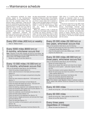 5
5 6
6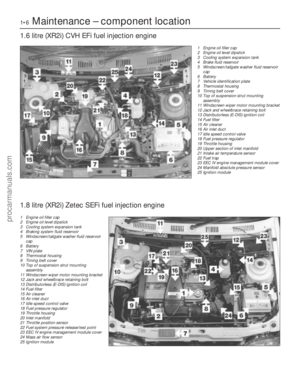 7
7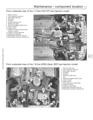 8
8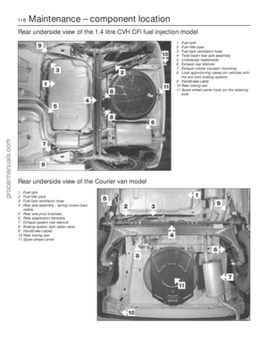 9
9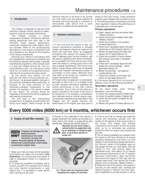 10
10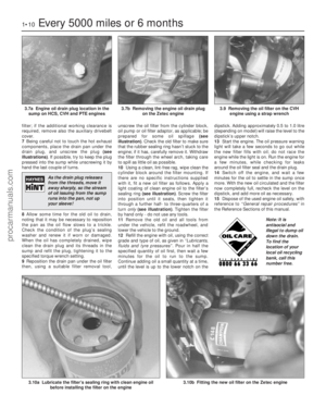 11
11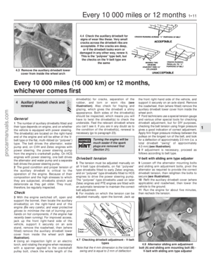 12
12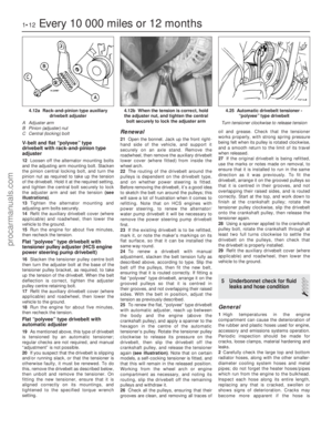 13
13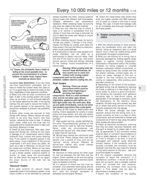 14
14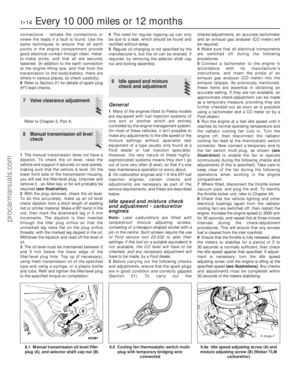 15
15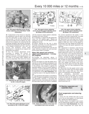 16
16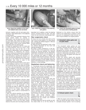 17
17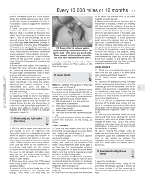 18
18 19
19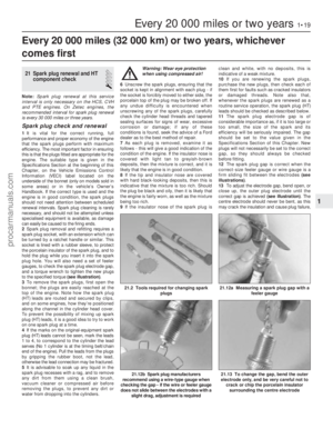 20
20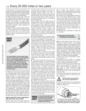 21
21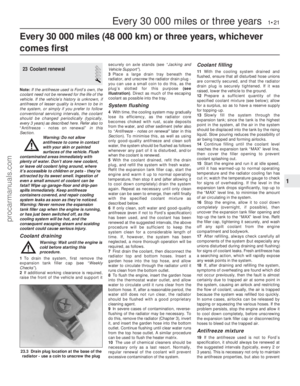 22
22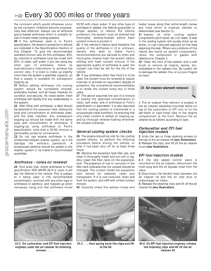 23
23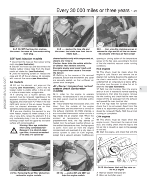 24
24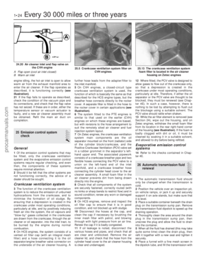 25
25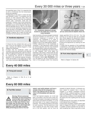 26
26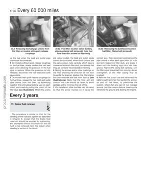 27
27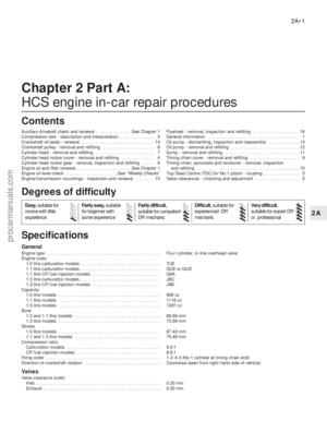 28
28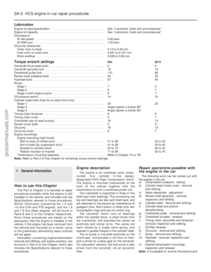 29
29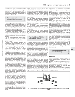 30
30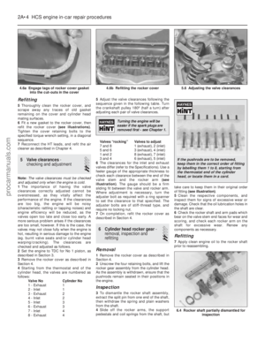 31
31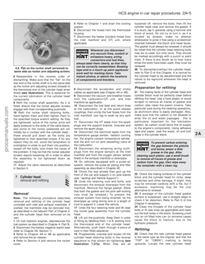 32
32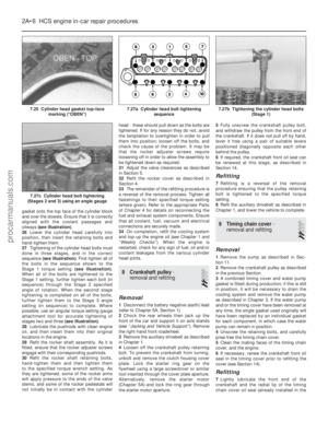 33
33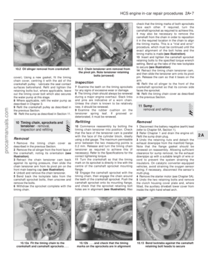 34
34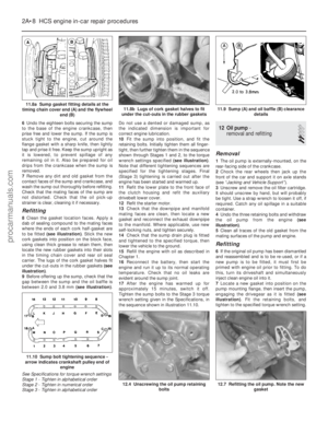 35
35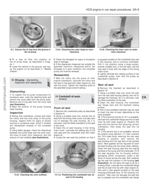 36
36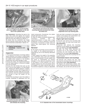 37
37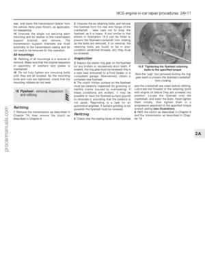 38
38 39
39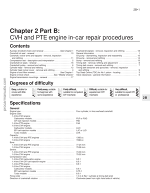 40
40 41
41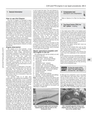 42
42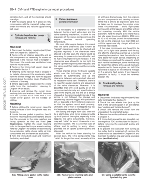 43
43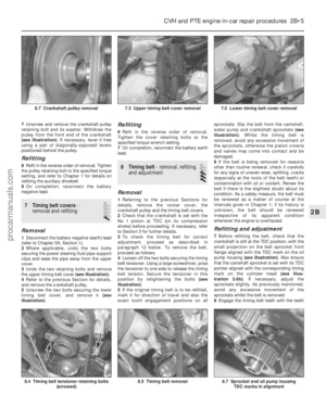 44
44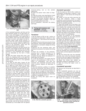 45
45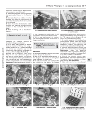 46
46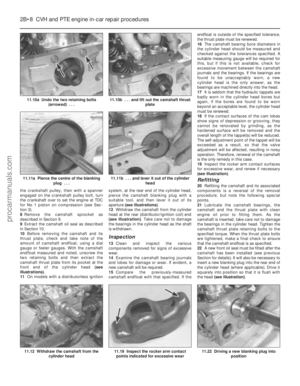 47
47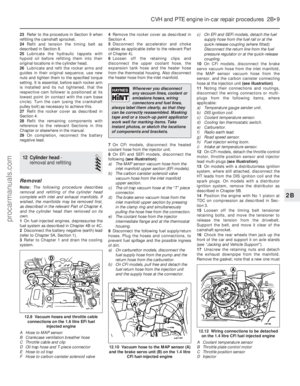 48
48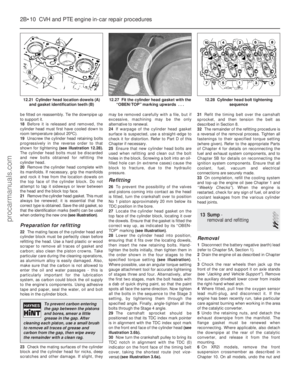 49
49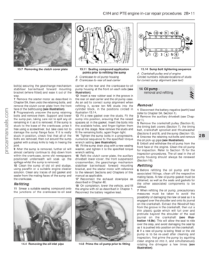 50
50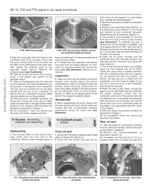 51
51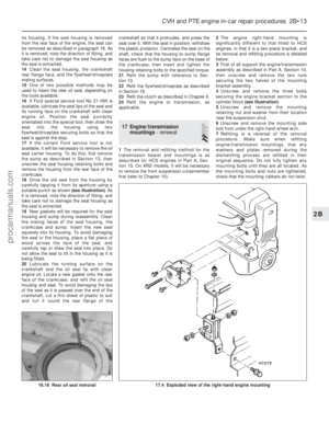 52
52 53
53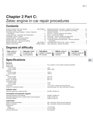 54
54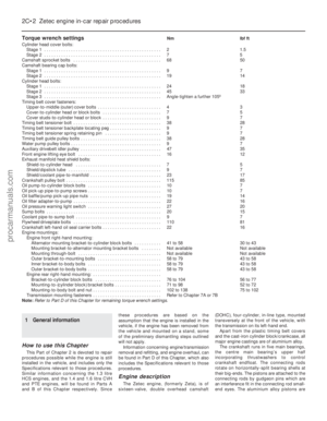 55
55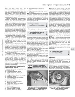 56
56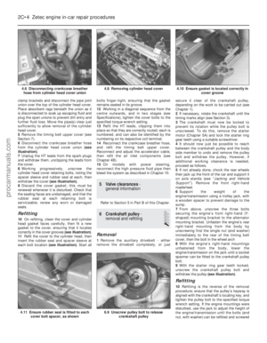 57
57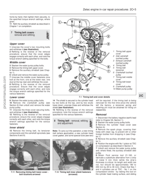 58
58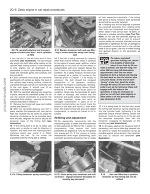 59
59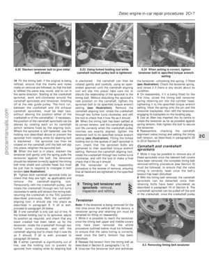 60
60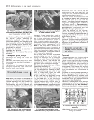 61
61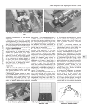 62
62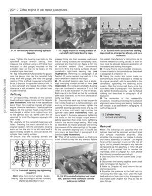 63
63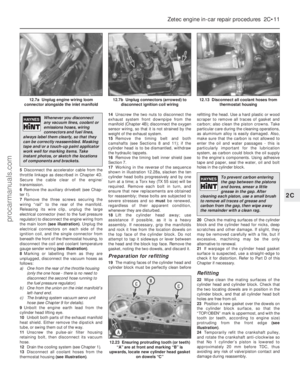 64
64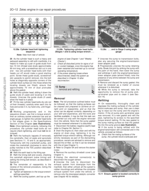 65
65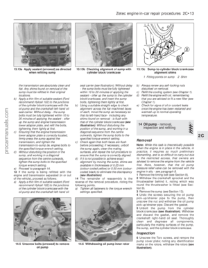 66
66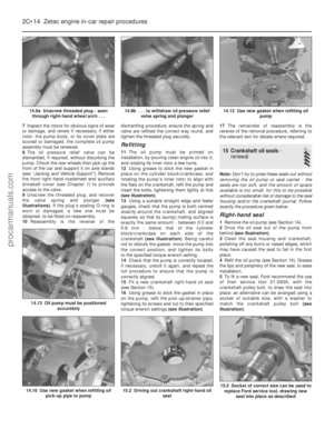 67
67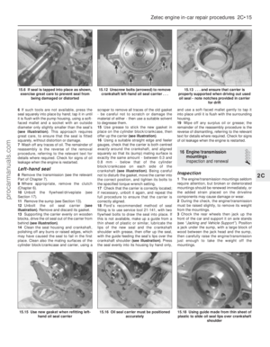 68
68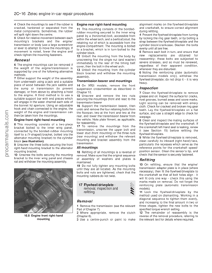 69
69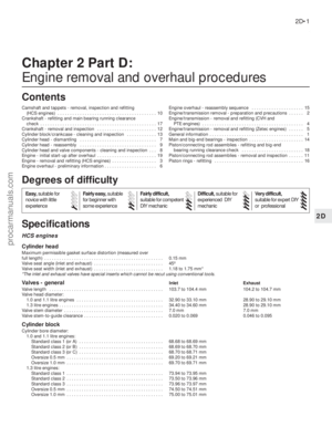 70
70 71
71 72
72 73
73 74
74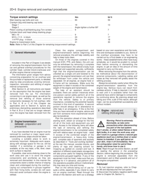 75
75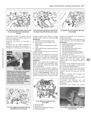 76
76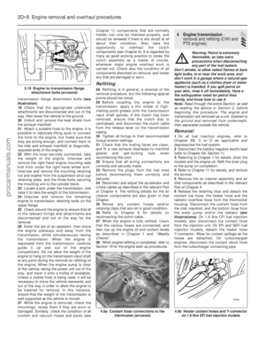 77
77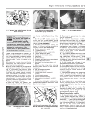 78
78 79
79 80
80 81
81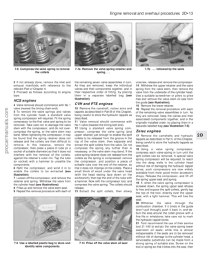 82
82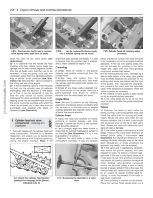 83
83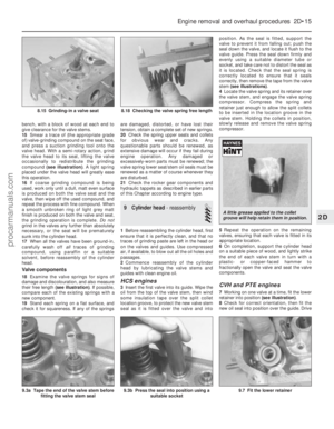 84
84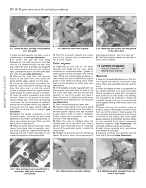 85
85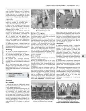 86
86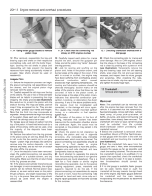 87
87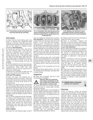 88
88 89
89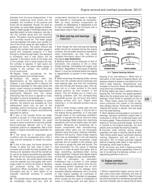 90
90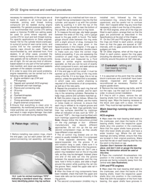 91
91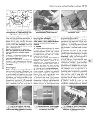 92
92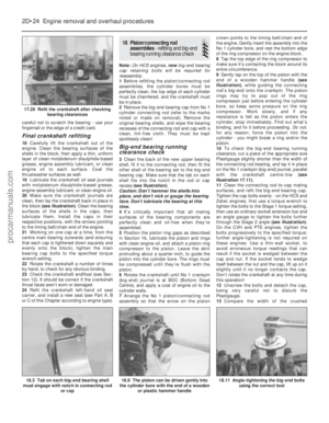 93
93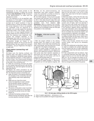 94
94 95
95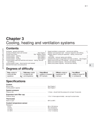 96
96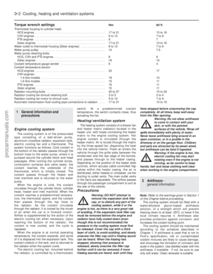 97
97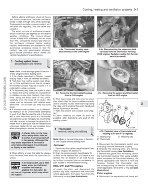 98
98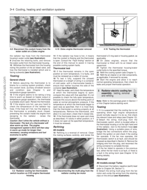 99
99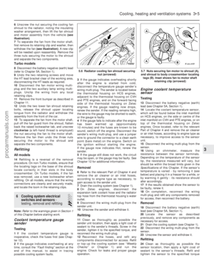 100
100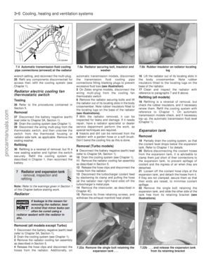 101
101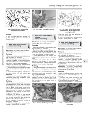 102
102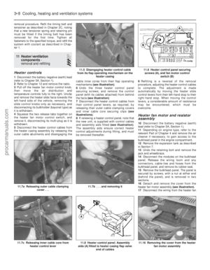 103
103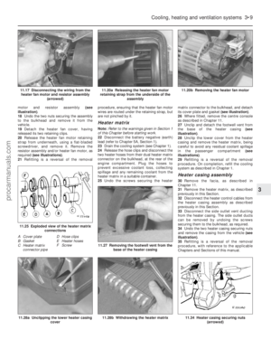 104
104 105
105 106
106 107
107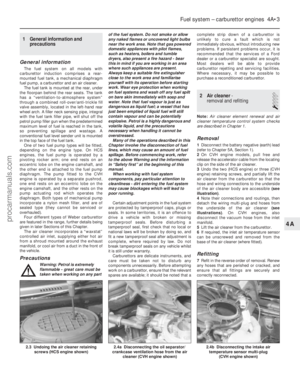 108
108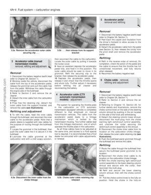 109
109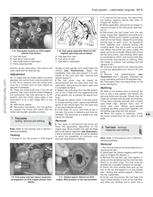 110
110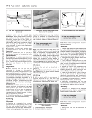 111
111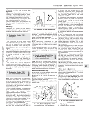 112
112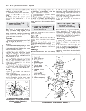 113
113 114
114 115
115 116
116 117
117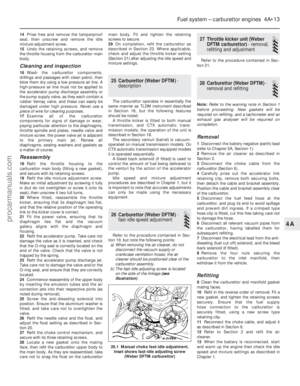 118
118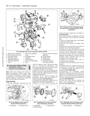 119
119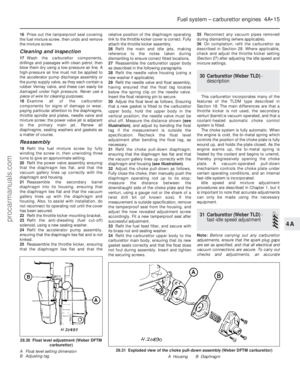 120
120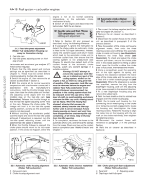 121
121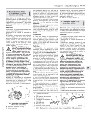 122
122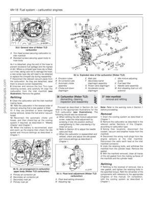 123
123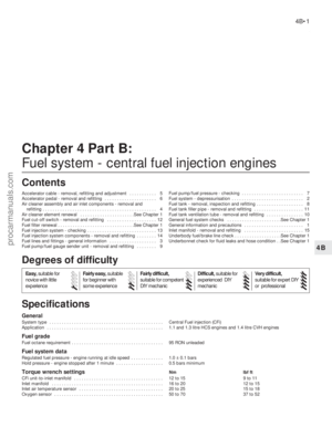 124
124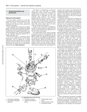 125
125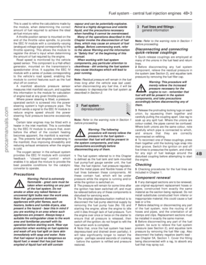 126
126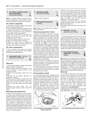 127
127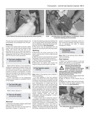 128
128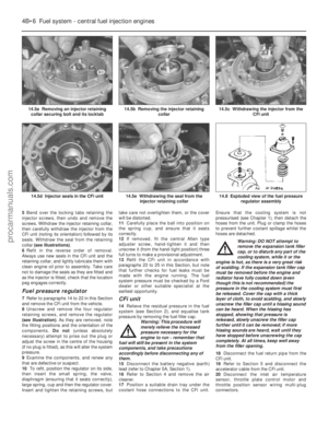 129
129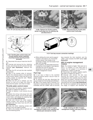 130
130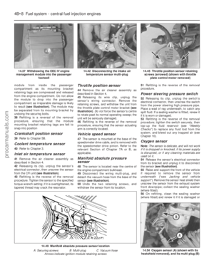 131
131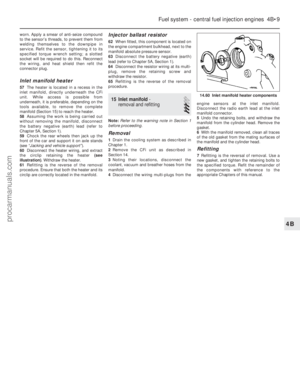 132
132 133
133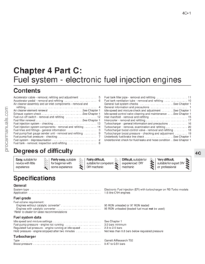 134
134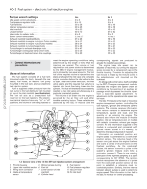 135
135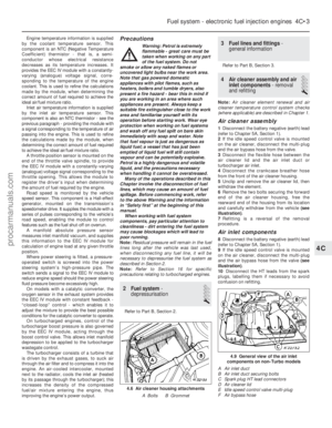 136
136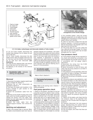 137
137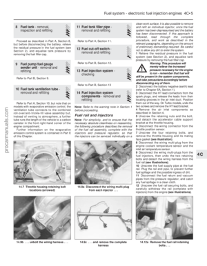 138
138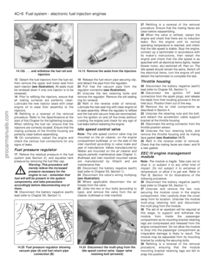 139
139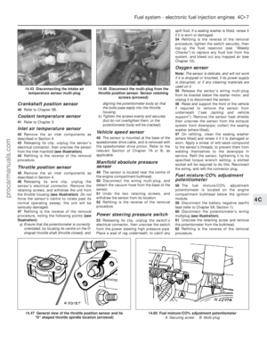 140
140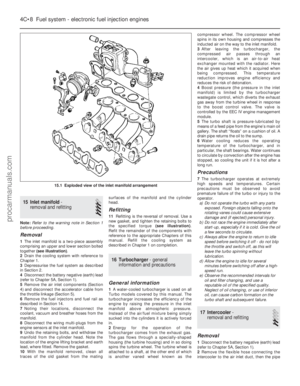 141
141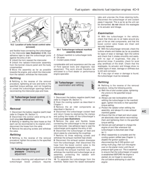 142
142 143
143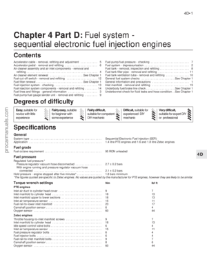 144
144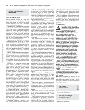 145
145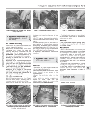 146
146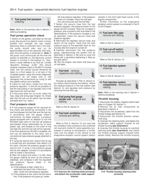 147
147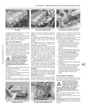 148
148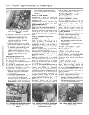 149
149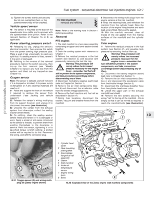 150
150 151
151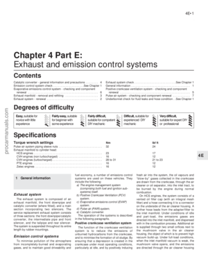 152
152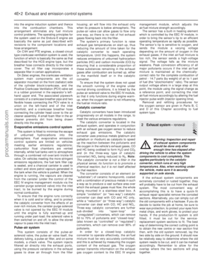 153
153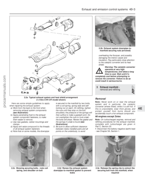 154
154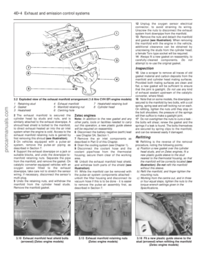 155
155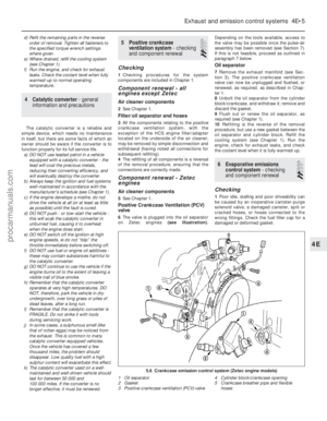 156
156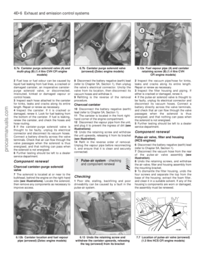 157
157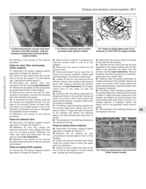 158
158 159
159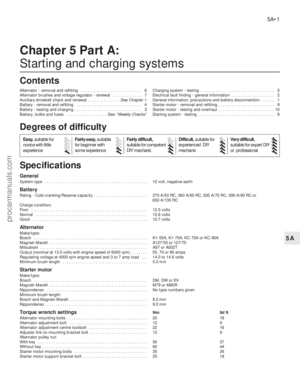 160
160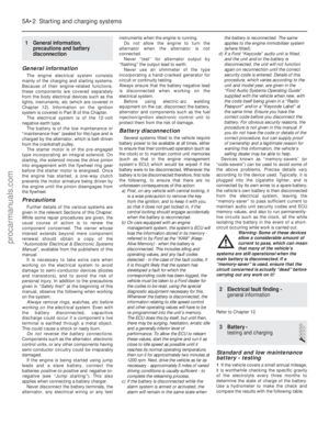 161
161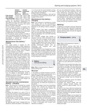 162
162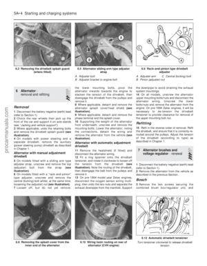 163
163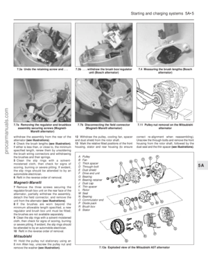 164
164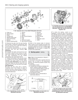 165
165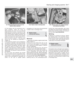 166
166 167
167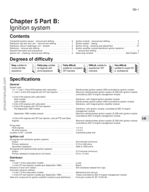 168
168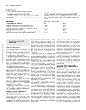 169
169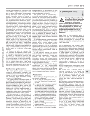 170
170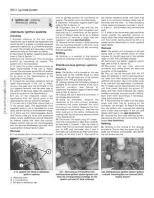 171
171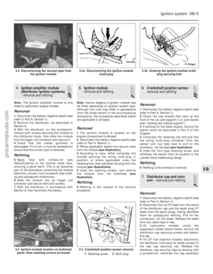 172
172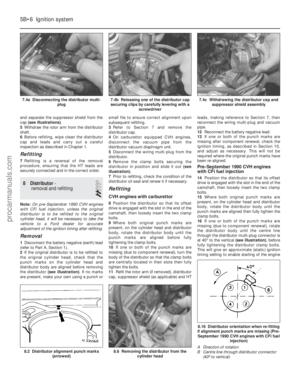 173
173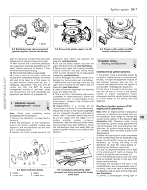 174
174 175
175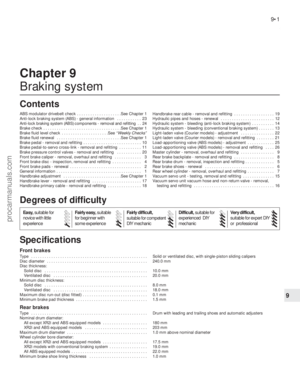 176
176 177
177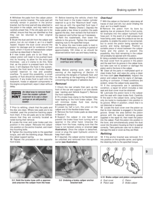 178
178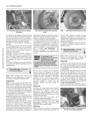 179
179 180
180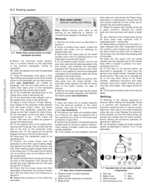 181
181 182
182 183
183 184
184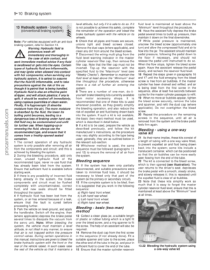 185
185 186
186 187
187 188
188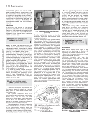 189
189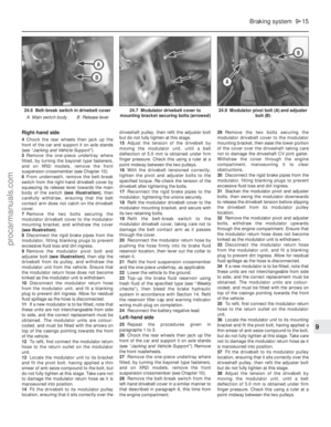 190
190 191
191 192
192 193
193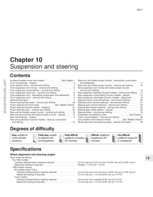 194
194 195
195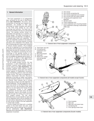 196
196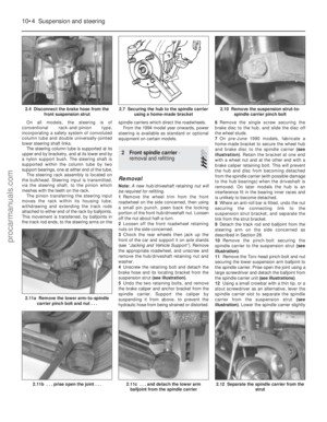 197
197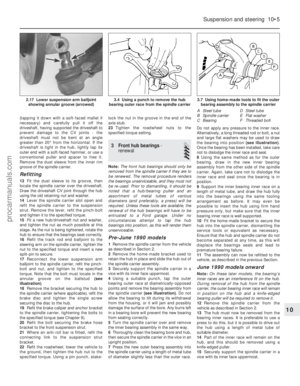 198
198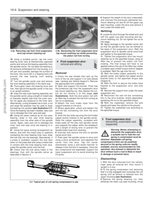 199
199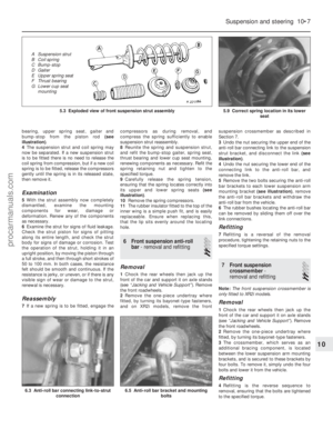 200
200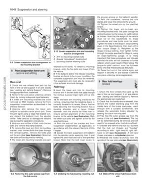 201
201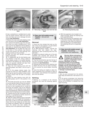 202
202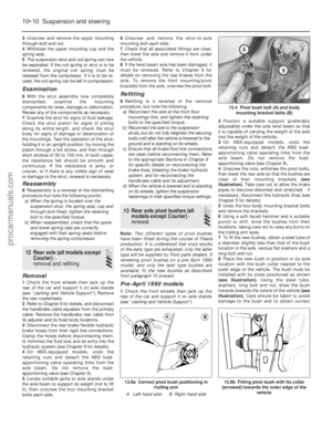 203
203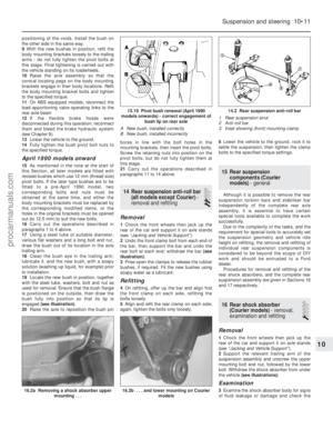 204
204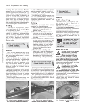 205
205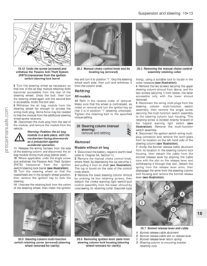 206
206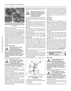 207
207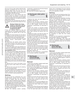 208
208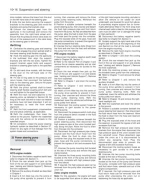 209
209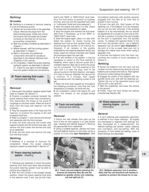 210
210 211
211 212
212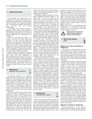 213
213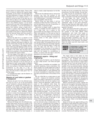 214
214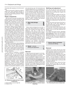 215
215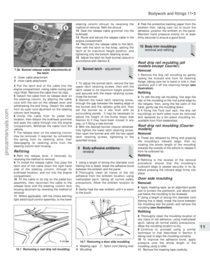 216
216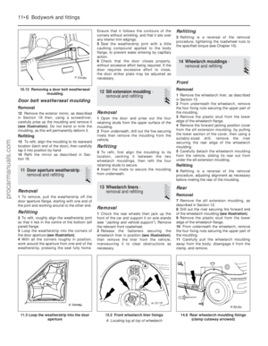 217
217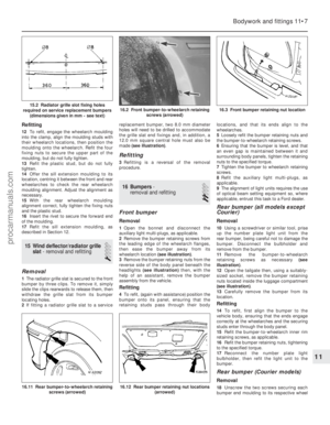 218
218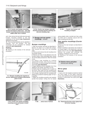 219
219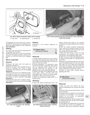 220
220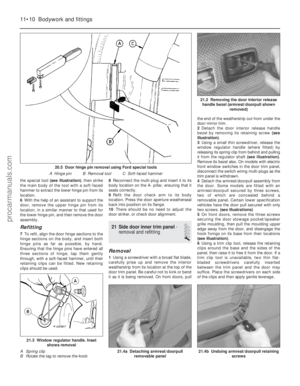 221
221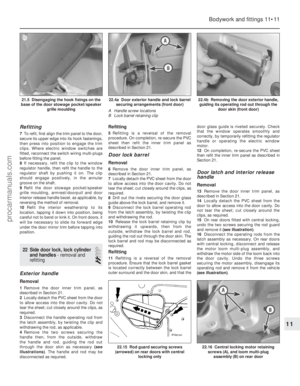 222
222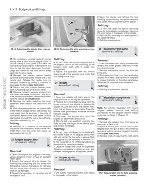 223
223 224
224 225
225 226
226 227
227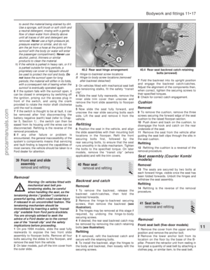 228
228 229
229 230
230 231
231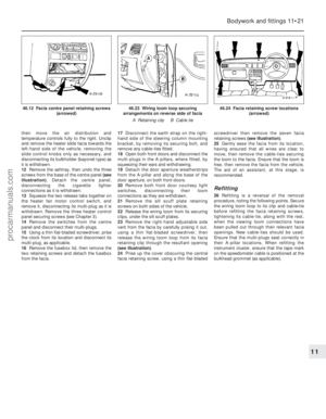 232
232 233
233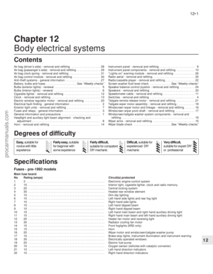 234
234 235
235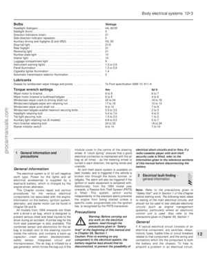 236
236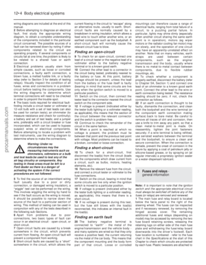 237
237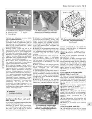 238
238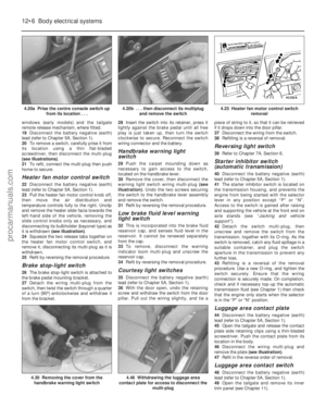 239
239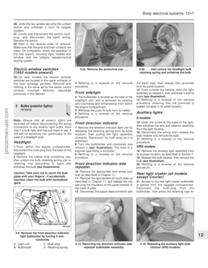 240
240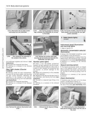 241
241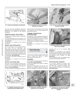 242
242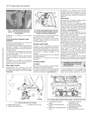 243
243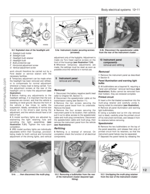 244
244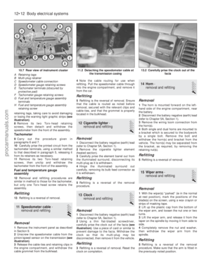 245
245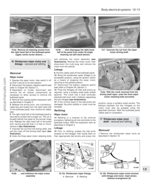 246
246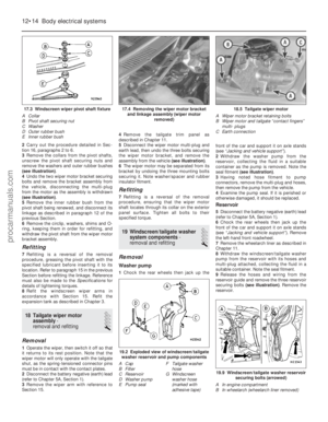 247
247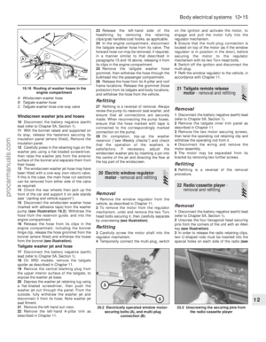 248
248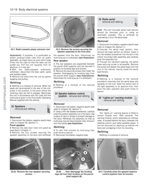 249
249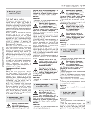 250
250 251
251 252
252 253
253 254
254 255
255 256
256 257
257 258
258 259
259 260
260 261
261 262
262 263
263 264
264 265
265 266
266 267
267 268
268 269
269 270
270 271
271 272
272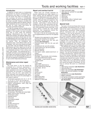 273
273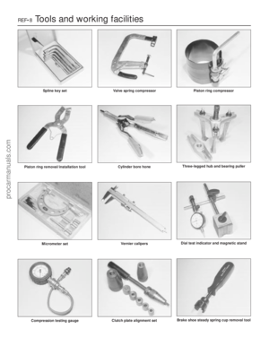 274
274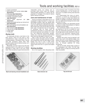 275
275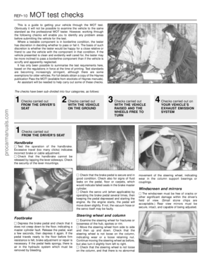 276
276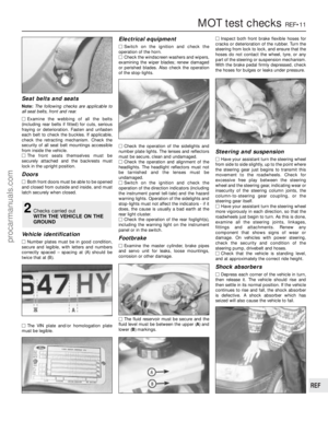 277
277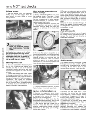 278
278 279
279 280
280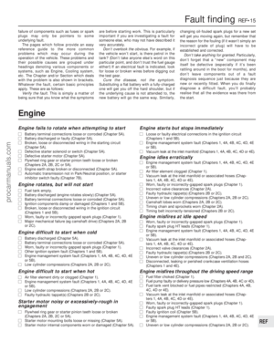 281
281 282
282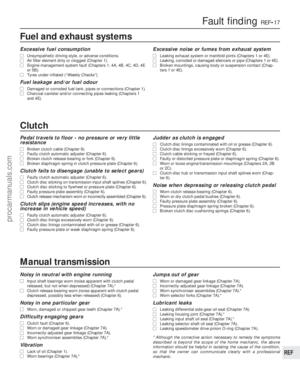 283
283 284
284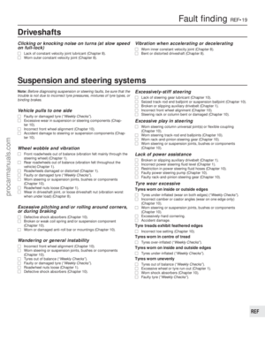 285
285 286
286 287
287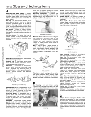 288
288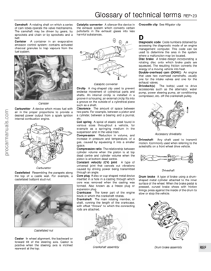 289
289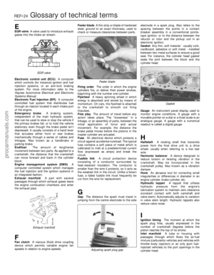 290
290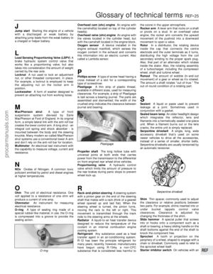 291
291 292
292 293
293 294
294 295
295