Page 161 of 296

1 General information,precautions and battery
disconnection
General information
The engine electrical system consists
mainly of the charging and starting systems.
Because of their engine-related functions,
these components are covered separately
from the body electrical devices such as the
lights, instruments, etc (which are covered in
Chapter 12). Information on the ignition
system is covered in Part B of this Chapter.
The electrical system is of the 12-volt
negative earth type. The battery is of the low maintenance or
“maintenance-free” (sealed for life) type and is
charged by the alternator, which is belt-driven
from the crankshaft pulley. The starter motor is of the pre-engaged
type incorporating an integral solenoid. On
starting, the solenoid moves the drive pinion
into engagement with the flywheel ring gear
before the starter motor is energised. Once
the engine has started, a one-way clutch
prevents the motor armature being driven by
the engine until the pinion disengages from
the flywheel.
Precautions
Further details of the various systems are
given in the relevant Sections of this Chapter.
While some repair procedures are given, the
usual course of action is to renew the
component concerned. The owner whose
interest extends beyond mere component
renewal should obtain a copy of the
“Automobile Electrical & Electronic Systems
Manual” , available from the publishers of this
manual. It is necessary to take extra care when
working on the electrical system to avoid
damage to semi-conductor devices (diodes
and transistors), and to avoid the risk of
personal injury. In addition to the precautions
given in “Safety first!” at the beginning of this
manual, observe the following when working
on the system:
Always remove rings, watches, etc before
working on the electrical system. Even with
the battery disconnected, capacitive
discharge could occur if a component’s live
terminal is earthed through a metal object.
This could cause a shock or nasty burn. Do not reverse the battery connections.
Components such as the alternator, electronic
control units, or any other components having
semi-conductor circuitry could be irreparably
damaged. If the engine is being started using jump
leads and a slave battery, connect the
batteries positive-to-positive and negative-to-
negative (see “Jump starting” ). This also
applies when connecting a battery charger.
Never disconnect the battery terminals, the
alternator, any electrical wiring or any test instruments when the engine is running.
Do not allow the engine to turn the
alternator when the alternator is not
connected. Never “test” for alternator output by
“flashing” the output lead to earth.
Never use an ohmmeter of the type
incorporating a hand-cranked generator for
circuit or continuity testing.
Always ensure that the battery negative lead
is disconnected when working on the
electrical system. Before using electric-arc welding
equipment on the car, disconnect the battery,
alternator and components such as the fuel
injection/ignition electronic control unit to
protect them from the risk of damage.
Battery disconnection
Several systems fitted to the vehicle require
battery power to be available at all times, either
to ensure that their continued operation (such as
the clock) or to maintain control unit memories
(such as that in the engine management
system’s ECU) which would be wiped if the
battery were to be disconnected. Whenever the
battery is to be disconnected therefore, first note
the following, to ensure that there are no
unforeseen consequences of this action:
a) First, on any vehicle with central locking, it is a wise precaution to remove the key
from the ignition, and to keep it with you,
so that it does not get locked in, if the
central locking should engage accidentally
when the battery is reconnected.
b) On cars equipped with an engine
management system, the system’s ECU will
lose the information stored in its memory -
referred to by Ford as the “KAM” (Keep-
Alive Memory) - when the battery is
disconnected. This includes idling and
operating values, and any fault codes
detected - in the case of the fault codes, if
it is thought likely that the system has
developed a fault for which the
corresponding code has been logged, the
vehicle must be taken to a Ford dealer for
the codes to be read, using the special
diagnostic equipment necessary for this.
Whenever the battery is disconnected, the
information relating to idle speed control
and other operating values will have to be
re-programmed into the unit’s memory.
The ECU does this by itself, but until then,
there may be surging, hesitation, erratic idle
and a generally inferior level of
performance. To allow the ECU to relearn
these values, start the engine and run it as
close to idle speed as possible until it
reaches its normal operating temperature,
then run it for approximately two minutes at
1200 rpm. Next, drive the vehicle as far as
necessary - approximately 5 miles of varied
driving conditions is usually sufficient - to
complete the relearning process.
c) If the battery is disconnected while the alarm system is armed or activated, the
alarm will remain in the same state when the battery is reconnected. The same
applies to the engine immobiliser system
(where fitted).
d) If a Ford “Keycode” audio unit is fitted,
and the unit and/or the battery is
disconnected, the unit will not function
again on reconnection until the correct
security code is entered. Details of this
procedure, which varies according to the
unit and model year, are given in the
“Ford Audio Systems Operating Guide”
supplied with the vehicle when new, with
the code itself being given in a “Radio
Passport” and/or a “Keycode Label” at
the same time. Ensure you have the
correct code before you disconnect the
battery. For obvious security reasons, the
procedure is not given in this manual. If
you do not have the code or details of the
correct procedure, but can supply proof
of ownership and a legitimate reason for
wanting this information, the vehicle’s
selling dealer may be able to help.
Devices known as “memory-savers” (or
“code-savers”) can be used to avoid some of
the above problems. Precise details vary
according to the device used. Typically, it is
plugged into the cigarette lighter, and is
connected by its own wires to a spare battery;
the vehicle’s own battery is then disconnected
from the electrical system, leaving the
“memory-saver” to pass sufficient current to
maintain audio unit security codes and ECU
memory values, and also to run permanently-
live circuits such as the clock, all the while
isolating the battery in the event of a short-
circuit occurring while work is carried out.
Warning: Some of these devices
allow a considerable amount of
current to pass, which can mean
that many of the vehicle’s
systems are still operational when the
main battery is disconnected. If a
“memory-saver” is used, ensure that the
circuit concerned is actually “dead” before
carrying out any work on it!
2 Electrical fault finding - general information
Refer to Chapter 12.
3 Battery -testing and charging
1
Standard and low maintenance
battery - testing
1If the vehicle covers a small annual mileage,
it is worthwhile checking the specific gravity
of the electrolyte every three months to
determine the state of charge of the battery.
Use a hydrometer to make the check and
compare the results with the following table.
5A•2 Starting and charging systems
1595Ford Fiesta Remakeprocarmanuals.com
http://vnx.su
Page 162 of 296
 25°C (77°F)
Fully-charged 1.210 to 1.230 1.270 to 1.290
70% charged 1.170 to 1.190 1.230 to 1.250
Fully-discharged 1.050 to 1.070")
Ambient Ambient
temperature temperature
abovebelow
25°C (77°F) 25°C (77°F)
Fully-charged 1.210 to 1.230 1.270 to 1.290
70% charged 1.170 to 1.190 1.230 to 1.250
Fully-discharged 1.050 to 1.070 1.110 to 1.130
Note that the specific gravity readings
assume an electrolyte temperature of
15°C (60°F); for every 10°C (18°F) below 15°C
(60°F) subtract 0.007. For every 10°C (18°F)
above 15°C (60°F) add 0.007.
2 If the battery condition is suspect, first
check the specific gravity of electrolyte in
each cell. A variation of 0.040 or more
between any cells indicates loss of electrolyte
or deterioration of the internal plates.
3 If the specific gravity variation is 0.040 or
more, the battery should be renewed. If the
cell variation is satisfactory but the battery is
discharged, it should be charged as
described later in this Section.
Maintenance-free battery -
testing
4 In cases where a “sealed for life”
maintenance-free battery is fitted, topping-up
and testing of the electrolyte in each cell is not
possible. The condition of the battery can
therefore only be tested using a battery
condition indicator or a voltmeter.
5 If testing the battery using a voltmeter,
connect the voltmeter across the battery and
compare the result with those given in the
Specifications under “charge condition”. The
test is only accurate if the battery has not
been subjected to any kind of charge for the
previous six hours. If this is not the case,
switch on the headlights for 30 seconds, then
wait four to five minutes before testing the
battery after switching off the headlights. All
other electrical circuits must be switched off,
so check that the doors and tailgate are fully
shut when making the test.
6 If the voltage reading is less than 12.2 volts,
then the battery is discharged, whilst a
reading of 12.2 to 12.4 volts indicates a
partially discharged condition.
7 If the battery is to be charged, remove it
from the vehicle (Section 4) and charge it as
described later in this Section.
Standard and low maintenance
battery - charging
Note: The following is intended as a guide
only. Always refer to the manufacturer’s
recommendations (often printed on a label
attached to the battery) before charging a
battery.
8 Charge the battery at a rate of 3.5 to
4 amps and continue to charge the battery at
this rate until no further rise in specific gravity
is noted over a four hour period.
9 Alternatively, a trickle charger charging at
the rate of 1.5 amps can safely be used
overnight.
10 Specially rapid “boost” charges which are
claimed to restore the power of the battery in 1 to 2 hours are not recommended, as they
can cause serious damage to the battery
plates through overheating.
11
While charging the battery, note that the
temperature of the electrolyte should never
exceed 37.8°C (100°F).
Maintenance-free battery -
charging
Note: The following is intended as a guide
only. Always refer to the manufacturer’s
recommendations (often printed on a label
attached to the battery) before charging a
battery.
12 This battery type takes considerably
longer to fully recharge than the standard
type, the time taken being dependent on the
extent of discharge, but it can take anything
up to three days.
13 A constant voltage type charger is
required, to be set, when connected, to 13.9
to 14.9 volts with a charger current below
25 amps. Using this method, the battery
should be usable within three hours, giving a
voltage reading of 12.5 volts, but this is for a
partially discharged battery and, as
mentioned, full charging can take
considerably longer.
14 If the battery is to be charged from a fully
discharged state (condition reading less than
12.2 volts), have it recharged by your Ford
dealer or local automotive electrician, as the
charge rate is higher and constant supervision
during charging is necessary.
4 Battery -
removal and refitting
1
Note: Refer to the precautions in Section 1
before starting work.
Removal
1 The battery is located forward on the left-
hand side of the engine compartment, on a
platform welded to the vehicle structure.
2 Undo the retaining nut, then detach the
earth leads from the stud of the battery
negative (earth) terminal post. This is the
terminal to disconnect before working on, or
disconnecting, any electrical component on
the vehicle.
3 Pivot up the plastic cover from the positive
terminal, then unscrew the positive lead
retaining nut on the terminal. Detach the
positive lead from the terminal.
4 Release the clamp securing the battery to
its platform and remove it. Lift the battery
from its location, keeping it in an upright
position to avoid the possibility of corrosive
electrolyte spilling onto the paintwork.
5 Clean the battery terminal posts, clamps
and the battery casing. If the bulkhead is
rusted as a result of battery acid spilling onto
it, clean it thoroughly and re-paint with
reference to Chapter 1. 6
If you are renewing the battery, make sure
that you get one that’s identical, with the
same dimensions, amperage rating, cold
cranking rating, etc. Dispose of the old battery
in a responsible fashion. Most local authorities
have facilities for the collection and disposal
of such items - batteries contain sulphuric
acid and lead, and should not be simply
thrown out with the household rubbish!
Refitting
7 Refitting is a reversal of removal. Smear the
battery terminals with a petroleum-based jelly
prior to reconnecting. Always connect the
positive terminal clamp first and the negative
terminal clamp last.
5 Charging system - testing
2
Note:Refer to the precautions in Section 1
before starting work.
1 If the ignition warning light fails to
illuminate when the ignition is switched on,
first check the alternator wiring connections
for security. If satisfactory, check that the
warning light bulb has not blown, and that
the bulbholder is secure in its location in the
instrument panel. If the light still fails to
illuminate, check the continuity of the
warning light feed wire from the alternator to
the bulbholder. If all is satisfactory, the
alternator is at fault and should be renewed
or taken to an auto-electrician for testing and
repair.
2 If the ignition warning light illuminates when
the engine is running, stop the engine and
check that the drivebelt is correctly tensioned
(see Chapter 1) and that the alternator
connections are secure. If all is so far
satisfactory, have the alternator checked by
an auto-electrician for testing and repair.
3 If the alternator output is suspect even
though the warning light functions correctly,
the regulated voltage may be checked as
follows.
4 Connect a voltmeter across the battery
terminals and start the engine.
5 Increase the engine speed until the
voltmeter reading remains steady; the
reading should be approximately 13.5 to
14.6 volts.
6 Switch on as many electrical accessories
(eg, the headlights, heated rear window and
heater blower) as possible, and check that the
alternator maintains the regulated voltage at
around 13 to 14 volts.
7 If the regulated voltage is not as stated, the
fault may be due to worn brushes, weak brush
springs, a faulty voltage regulator, a faulty
diode, a severed phase winding or worn or
damaged slip rings. The alternator should be
renewed or taken to an auto-electrician for
testing and repair.
Starting and charging systems 5A•3
5A
1595Ford Fiesta Remakeprocarmanuals.com
http://vnx.su
Page 163 of 296
 lead
(refer to Section 1).
2 Chock the rear wheels then jack up the
front of the car and support it on axle sta")
6 Alternator-
removal and refitting
2
Removal
1 Disconnect the battery negative (earth) lead
(refer to Section 1).
2 Chock the rear wheels then jack up the
front of the car and support it on axle stands
(see “Jacking and vehicle support” ).
3 Where applicable, undo the retaining bolts
and remove the drivebelt splash guard (see
illustration) .
4 On models with power steering and a
separate drivebelt, remove the auxiliary
(power steering pump) drivebelt as described
in Chapter 1.
Alternator with manual adjustment
drivebelt
5 On models fitted with a sliding arm type
adjuster strap, unscrew and remove the top
(adjuster) bolt from the strap (see
illustration) .
6 On models fitted with a “rack-and-pinion”
type adjuster, unscrew and remove the
central (locking) bolt whilst, at the same time,
loosening the (adjuster) nut (see illustration).
7 Loosen off, but do not yet remove, the lower mounting bolts, pivot the
alternator inwards towards the engine to
slacken the tension of the drivebelt, then
disengage the drivebelt from the pulleys and
remove it.
8
Where applicable, detach and remove the
alternator splash cover/heat shield (see
illustration) .
9 Where applicable, detach and remove the
phase terminal and the splash cover.
10 Supporting the weight of the alternator
from underneath, unscrew and remove the
mounting bolts. Lower the alternator; noting
the connections, detach the wiring and
remove the alternator from the vehicle (see
illustration) .
Alternator with automatic adjustment
drivebelt
11Remove the heatshield (if fitted) and
disconnect the alternator wiring.
12 Fit a ring spanner onto the drivebelt
tensioner, and rotate it clockwise to loosen off
the tension from the drivebelt (see
illustration) . Note the routing of the drivebelt,
then disengage the belt from the pulleys and
remove it.
13 On pre-1994 model year Zetec engines,
disconnect the oxygen sensor wiring multi-
plug, then undo the two nuts and separate the
exhaust downpipe from the manifold. Support the downpipe to avoid straining the exhaust
system mountings.
14
On all models, unscrew the alternator
upper mounting bolts/nuts and disconnect the
alternator wiring. Unscrew the lower
bolts/nuts and remove the alternator from the
engine. On pre-1994 Zetec engines, it will be
necessary to de-tension the drivebelt
tensioner to provide clearance for removal of
the upper mounting bolt nut.
Refitting
15 Refit in the reverse order of removal. Refit
the drivebelt, and ensure that it is correctly re-
routed around the pulleys. Adjust the tension
of the drivebelt (according to type) as
described in Chapter 1.
7 Alternator brushes and voltage regulator - renewal
3
1Disconnect the battery negative (earth) lead
(refer to Section 1).
2 Remove the alternator from the vehicle as
described in the previous Section.
Bosch
3 Remove the two screws securing the
combined brush box/regulator unit, and
5A•4 Starting and charging systems
6.12 Automatic drivebelt tensioner
Turn tensioner clockwise to release drivebelt tension
6.10 Wiring loom routing on rear ofalternator (CVH engine)6.8 Removing the splash cover from the inner end of the alternator
6.6 Rack-and-pinion type drivebelt adjuster
A Adjuster arm C Central (locking) bolt
B Pinion (adjuster) nut6.5 Alternator sliding arm type adjuster strap
A Adjuster bolt
B Adjuster bracket to engine bolt6.3 Removing the drivebelt splash guard (where fitted)
1595Ford Fiesta Remakeprocarmanuals.com
http://vnx.su
Page 164 of 296
 .
4 Check the brush lengths (see illustration).
If either is less than, or close to, the minimum
specified length, renew them")
withdraw the assembly from the rear of the
alternator (see illustrations) .
4 Check the brush lengths (see illustration).
If either is less than, or close to, the minimum
specified length, renew them by unsoldering
the brush wiring connectors and withdrawing
the brushes and their springs.
5 Clean the slip rings with a solvent-
moistened cloth, then check for signs of
scoring, burning or severe pitting. If evident,
the slip rings should be attended to by an
automobile electrician.
6 Refit in the reverse order of removal.
Magneti-Marelli
7Remove the three screws securing the
regulator/brush box unit on the rear face of the
alternator, partially withdraw the assembly,
detach the field connector, and remove the
unit from the alternator (see illustrations).
8 If the brushes are worn beyond the
minimum allowable length specified, a new
regulator and brush box unit must be fitted;
the brushes are not available separately.
9 Clean the slip rings with a solvent-moistened
cloth, then check for signs of scoring, burning
or severe pitting. If evident, the slip rings should
be attended to by an automobile electrician.
10 Refit in the reverse order of removal.
Mitsubishi
11Hold the pulley nut stationary using an
8 mm Allen key, unscrew the pulley nut and
remove the washer (see illustration).12
Withdraw the pulley, cooling fan, spacer
and dust shield from the rotor shaft.
13 Mark the relative fitted positions of the front
housing, stator and rear housing (to ensure correct re-alignment when reassembling).
Unscrew the through-bolts and remove the front
housing from the rotor shaft, followed by the
dust seal and the thin spacer
(see illustrations).
Starting and charging systems 5A•5
7.4 Measuring the brush lengths (Bosch
alternator)7.3b . . . withdraw the brush box/regulatorunit (Bosch alternator)
7.11 Pulley nut removal on the Mitsubishi alternator
7.13a Exploded view of the Mitsubishi A5T alternator
7.7b Disconnecting the field connector(Magneti-Marelli alternator)7.7a Removing the regulator and brushboxassembly securing screws (Magneti- Marelli alternator)
5A
1595Ford Fiesta Remake
7.3a Undo the retaining screw and . . .
A Pulley
B Fan
C Thick spacer
D Through-bolt
E Dust shield
F Drive end unit
G Bearing
H Bearing retainer
J Dust cap
K Thin spacer
L Rotor
M Seal
N Bearing
O Commutator end
P Diode pack
R Brush box
S Stator
procarmanuals.com
http://vnx.su
Page 165 of 296

14Remove the rotor from the rear housing
and the stator. If difficulty is experienced, heat
the rear housing with a 200-watt soldering
iron for three or four minutes.
15 Unbolt the rectifier/brush box and stator
assembly from the rear housing (see
illustration) .
16 Unsolder the stator and brush box from
the rectifier, using the very minimum of heat.
Use a pair of pliers as a heat sink to reduce
the heat transference to the diodes
(overheating may cause diode failure).
17 Renew the brushes if they are worn down
to, or beyond, the minimum specified length.
Unsolder the brush wires at the points
indicated (see illustration) , then solder the
new brush leads so that the wear limit line
projects 2 to 3 mm from the end of the holder
(see illustration) .
18 Clean the slip rings with a solvent-
moistened cloth, then check for signs of
scoring, burning or severe pitting. If evident,
the slip rings should be attended to by an
automobile electrician. 19
Refit in the reverse order of removal.
Insert a piece of wire through the access hole
in the rear housing to hold the brushes in the
retracted position as the rotor is refitted (see
illustration) . Do not forget to release the
brushes when assembled.
8 Starting system - testing
1
Note:Refer to the precautions in Section 1
before starting work.
1 If the starter motor fails to operate when the
ignition key is turned to the appropriate
position, the following possible causes may
be to blame.
a) The battery is faulty.
b) The electrical connections between the
switch, solenoid, battery and starter
motor are somewhere failing to pass the
necessary current from the battery
through the starter to earth.
c) The solenoid is faulty.
d) The starter motor is mechanically or
electrically defective. 2
To check the battery, switch on the
headlights. If they dim after a few seconds,
this indicates that the battery is discharged -
recharge (see Section 3) or renew the battery.
If the headlights glow brightly, operate the
ignition switch and observe the lights. If they
dim, then this indicates that current is
reaching the starter motor, therefore the fault
must lie in the starter motor. If the lights
continue to glow brightly (and no clicking
sound can be heard from the starter motor
solenoid), this indicates that there is a fault in
the circuit or solenoid - see following
paragraphs. If the starter motor turns slowly
when operated, but the battery is in good
condition, then this indicates that either the
starter motor is faulty, or there is considerable
resistance somewhere in the circuit.
3 If a fault in the circuit is suspected,
disconnect the battery leads (including the
earth connection to the body), the starter/
solenoid wiring and the engine/transmission
earth strap. Thoroughly clean the
connections, and reconnect the leads and
wiring, then use a voltmeter or test lamp to
check that full battery voltage is available at
the battery positive lead connection to the
solenoid, and that the earth is sound. Smear
petroleum jelly around the battery terminals to
prevent corrosion - corroded connections are
amongst the most frequent causes of
electrical system faults.
5A•6 Starting and charging systems
7.19 Use a length of wire rod to hold
brushes in the retracted position when
reassembling the rotor to the housing on
the Mitsubishi alternator
7.17b Fitted position of new brush on a Mitsubishi alternator7.17a Unsoldering a brush wire on aMitsubishi alternator
7.15 Rectifier/brush box (1) and regulatorunit (3) retaining nuts on the Mitsubishialternator. Note that cap (2) covers the regulator nut
A Pulley nut
B Spring washer
C Pulley
D Through-bolt
E Retainer plate screw
F Drive end housing
G Bearing
H Bearing retaining plate J Spacer
K Rotor
L Spacer
M Slip ring end bearing
N Plug
P Cap
Q Terminal insulator
R Slip ring end housing S Rectifier
T Dust cover
V Regulator
W Brush spring
X Brush
Y Regulator screw
Z Stator
1595Ford Fiesta Remake
7.13b Exploded view of the AOO2T Mitsubishi alternatorprocarmanuals.com
http://vnx.su
Page 166 of 296

4If the battery and all connections are in
good condition, check the circuit by
disconnecting the wire from the solenoid
blade terminal. Connect a voltmeter or test
lamp between the wire end and a good earth
(such as the battery negative terminal), and
check that the wire is live when the ignition
switch is turned to the “start” position. If it is,
then the circuit is sound - if not the circuit
wiring can be checked as described in
Chapter 12.
5 The solenoid contacts can be checked by
connecting a voltmeter or test lamp between
the battery positive feed connection on the
starter side of the solenoid, and earth. When
the ignition switch is turned to the “start”
position, there should be a reading or lighted
bulb, as applicable. If there is no reading or
lighted bulb, the solenoid is faulty and should
be renewed.
6 If the circuit and solenoid are proved
sound, the fault must lie in the starter motor.
In this event, it may be possible to have the
starter motor overhauled by a specialist, but
check on the cost of spares before proceeding, as it may prove more economical
to obtain a new or exchange motor.
9 Starter motor
-
removal and refitting
1
Removal
1 Disconnect the battery negative (earth) lead
(refer to Section 1).
2 Chock the rear wheels then jack up the
front of the car and support it on axle stands
(see “Jacking and vehicle support” ). Remove
the front roadwheels.
3 Undo the two retaining nuts, and remove
the starter motor heat shield (where fitted).
4 Prise free the cap, if fitted, then unscrew the
nuts to disconnect the wiring from the
starter/solenoid terminals. Where applicable,
disconnect the oxygen sensor wiring multi-plug
from the locating bracket (see illustration).
5 Unscrew and remove the starter motor
retaining bolts at the transmission/clutch housing and, where applicable, also unbolt
and detach the support bracket. Withdraw the
starter motor from its mounting, and remove it
from the vehicle
(see illustrations) .
Refitting
6Refitting is a reversal of removal. Tighten
the retaining bolts to the specified torque.
Ensure that the wiring is securely reconnected
to the starter motor (and solenoid) and is
routed clear of the exhaust downpipe.
10 Starter motor - testing and overhaul
4
If the starter motor is thought to be suspect, it
should be removed from the vehicle and taken
to an auto-electrician for testing. Most auto-
electricians will be able to supply and fit
brushes at a reasonable cost. However, check
on the cost of repairs before proceeding as it
may prove more economical to obtain a new
or exchange motor.
Starting and charging systems 5A•7
9.5b Starter motor rear support bracket
and fasteners (arrowed)9.5a Starter motor retaining bolts9.4 Disconnecting the wires from thestarter motor solenoid
5A
1595Ford Fiesta Remakeprocarmanuals.com
http://vnx.su
Page 167 of 296
5A•8 Starting and charging systems
1595Ford Fiesta Remake
Notes
procarmanuals.com
http://vnx.su
Page 168 of 296
 controlled by ignition module
1.1 a")
5B
1595Ford Fiesta Remake
General
System type:1.0, 1.1 and 1.3 litre HCS engines with carburettor . . . . . . . . . . . . . . Distributorless ignition system (DIS) controlled by ignition module
1.1 and 1.3 litre HCS engines with CFi fuel injection . . . . . . . . . . . . . Electronic distributorless ignition system (E-DIS) with ignition module controlled by EEC IV engine management module
1.4 litre CVH engines with carburettor: Early models . . . . . . . . . . . . . . . . . . . . . . . . . . . . . . . . . . . .\
. . . . . . Distributor, with integral ignition amplifier module
Later models . . . . . . . . . . . . . . . . . . . . . . . . . . . . . . . . . . . .\
. . . . . . Distributorless ignition system (DIS) controlled by ignition module
1.6 litre CVH engines with carburettor . . . . . . . . . . . . . . . . . . . . . . . . Distributor, with integral ignition amplifier module
1.4 litre CVH engines with CFi fuel injection: Pre-September 1990 models . . . . . . . . . . . . . . . . . . . . . . . . . . . . . Distributor, with ignition module, controlled by EEC IV engine
management module
September 1990 models onward . . . . . . . . . . . . . . . . . . . . . . . . . . Electronic distributorless ignition system (E-DIS) with ignition module controlled by EEC IV engine management module
1.6 litre CVH engines with EFi fuel injection, and all PTE and Zetec
engines . . . . . . . . . . . . . . . . . . . . . . . . . . . . . . . . . . . .\
. . . . . . . . . . . . Electronic distributorless ignition system (E-DIS) with ignition module controlled by EEC IV engine management module
Firing order: HCS engines . . . . . . . . . . . . . . . . . . . . . . . . . . . . . . . . . . . .\
. . . . . . . . 1-2-4-3
All other engines . . . . . . . . . . . . . . . . . . . . . . . . . . . . . . . . . . . .\
. . . . . 1-3-4-2
Location of No 1 cylinder . . . . . . . . . . . . . . . . . . . . . . . . . . . . . . . . . . . .\
Crankshaft pulley end
Ignition coil
All engines with distributor ignition systems:
Output . . . . . . . . . . . . . . . . . . . . . . . . . . . . . . . . . . . .\
. . . . . . . . . . . . . 30.0 kilovolts (minimum)
Primary resistance . . . . . . . . . . . . . . . . . . . . . . . . . . . . . . . . . . . .\
. . . 0.72 to 0.88 ohms
Secondary resistance . . . . . . . . . . . . . . . . . . . . . . . . . . . . . . . . . . . .\
. 4500 to 7000 ohms
All engines with distributorless ignition systems: Output . . . . . . . . . . . . . . . . . . . . . . . . . . . . . . . . . . . .\
. . . . . . . . . . . . . 37.0 kilovolts (minimum)
Primary resistance (measured at coil tower) . . . . . . . . . . . . . . . . . . . . 0.5 to 1.0 ohm
Distributor
Make:
1.4 and 1.6 litre carburettor models . . . . . . . . . . . . . . . . . . . . . . . . . . Lucas
1.4 litre CFi fuel injection models (pre-September 1990) . . . . . . . . . . Bosch
Direction of rotor arm rotation . . . . . . . . . . . . . . . . . . . . . . . . . . . . . . . . Anti-clockwise (viewed from cap)
Automatic advance method: 1.4 and 1.6 litre carburettor models . . . . . . . . . . . . . . . . . . . . . . . . . . Mechanical and vacuum
1.4 litre CFi fuel injection models (pre-September 1990) . . . . . . . . . . Totally controlled by EEC IV engine management module
Heat sink compound for ignition amplifier module (Lucas distributor) . . Ford part number 81 SF-12103-AA
Chapter 5 Part B:
Ignition system
Crankshaft position sensor - removal and refitting . . . . . . . . . . . . . . 6
Distributor cap and rotor arm - removal and refitting . . . . . . . . . . . . 7
Distributor vacuum diaphragm unit - renewal . . . . . . . . . . . . . . . . . . 9
Distributor - removal and refitting . . . . . . . . . . . . . . . . . . . . . . . . . . . 8
General information and precautions . . . . . . . . . . . . . . . . . . . . . . . . 1
Ignition coil - checking, removal and refitting . . . . . . . . . . . . . . . . . . 3 Ignition module - removal and refitting . . . . . . . . . . . . . . . . . . . . . . . 5
Ignition system - testing . . . . . . . . . . . . . . . . . . . . . . . . . . . . . . . . . . 2
Ignition timing - checking and adjustment . . . . . . . . . . . . . . . . . . . . 10
Ignition amplifier module (distributor ignition systems) -
removal and refitting . . . . . . . . . . . . . . . . . . . . . . . . . . . . . . . . . . . 4
Spark plug renewal . . . . . . . . . . . . . . . . . . . . . . . . . . . . .See Chapter 1
5B•1
Specifications Contents
Easy, suitable for
novice with little
experience Fairly easy,
suitable
for beginner with
some experience Fairly difficult,
suitable for competent
DIY mechanic
Difficult,
suitable for
experienced DIY
mechanic Very difficult,
suitable for expert DIY
or professional
Degrees of difficulty
54321
procarmanuals.com
http://vnx.su
 1
1 2
2 3
3 4
4 5
5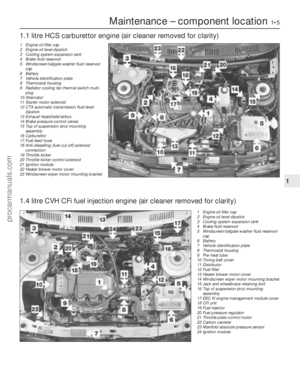 6
6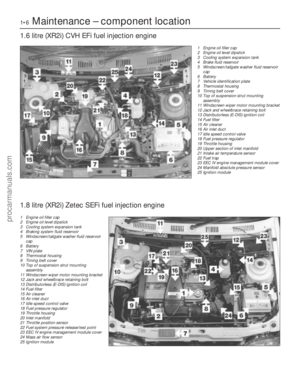 7
7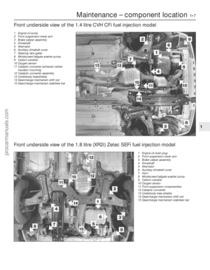 8
8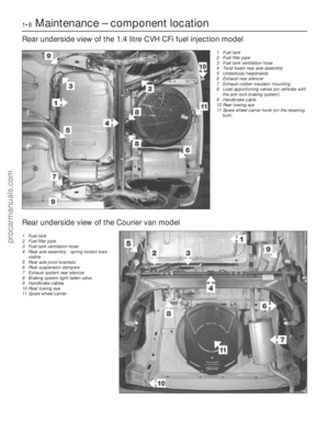 9
9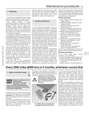 10
10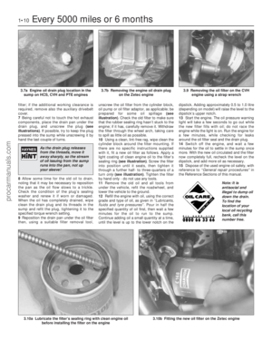 11
11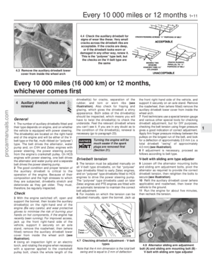 12
12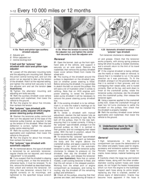 13
13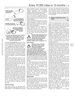 14
14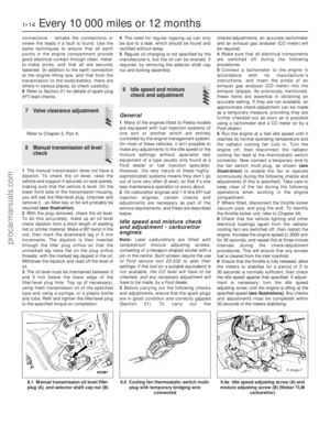 15
15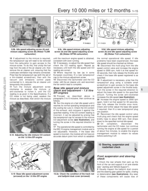 16
16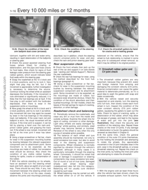 17
17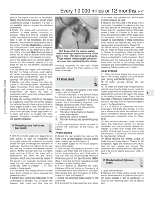 18
18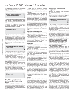 19
19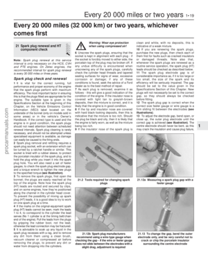 20
20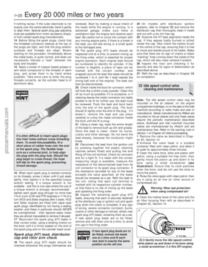 21
21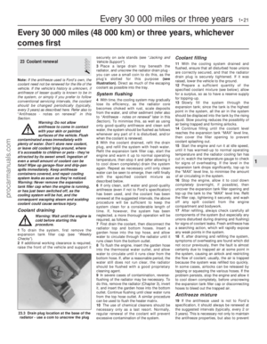 22
22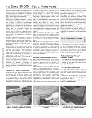 23
23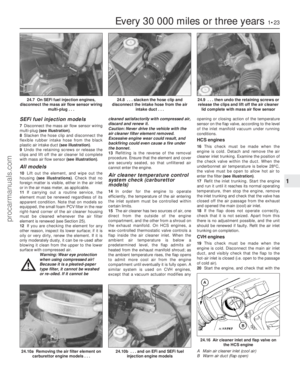 24
24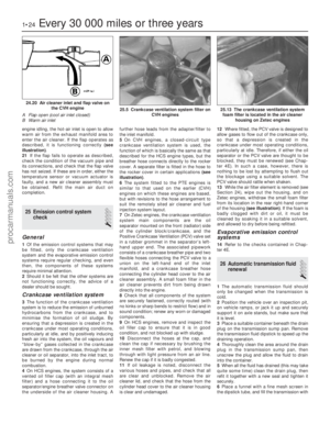 25
25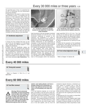 26
26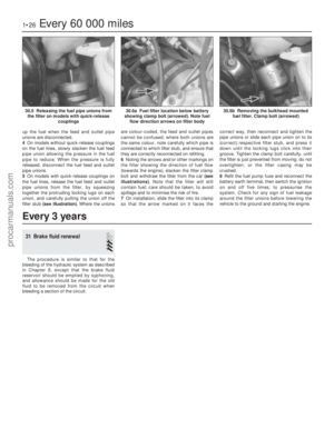 27
27 28
28 29
29 30
30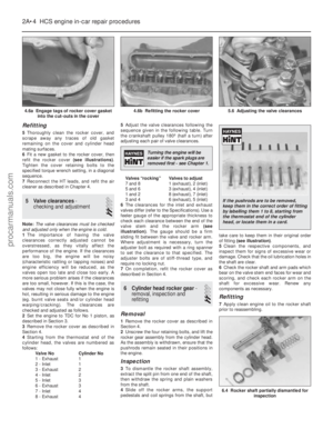 31
31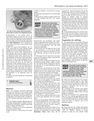 32
32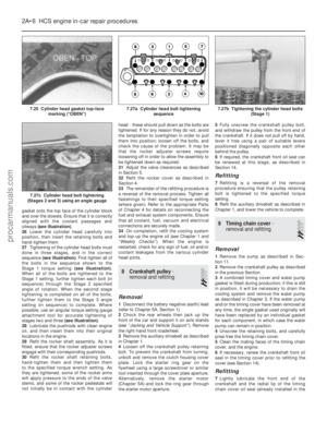 33
33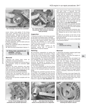 34
34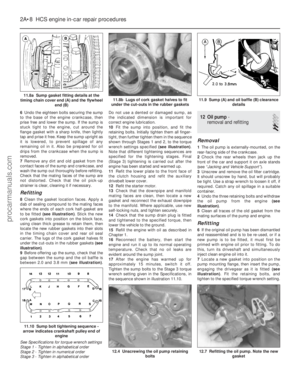 35
35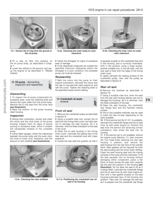 36
36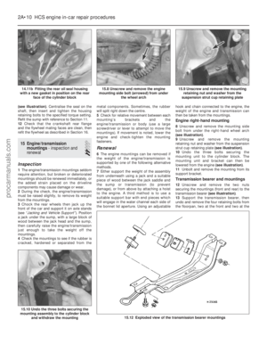 37
37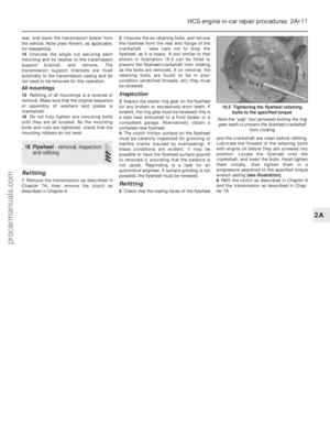 38
38 39
39 40
40 41
41 42
42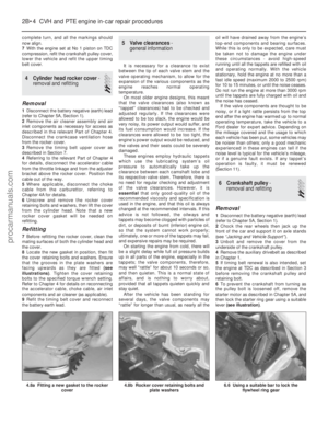 43
43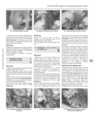 44
44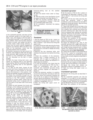 45
45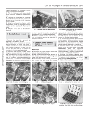 46
46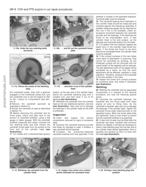 47
47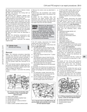 48
48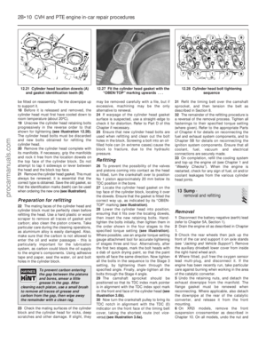 49
49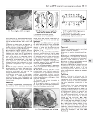 50
50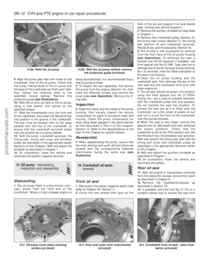 51
51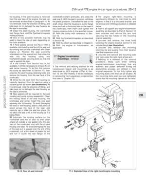 52
52 53
53 54
54 55
55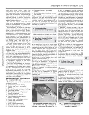 56
56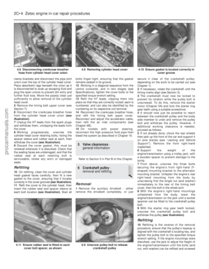 57
57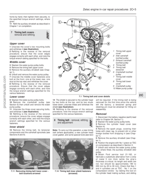 58
58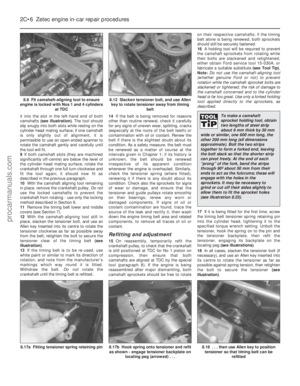 59
59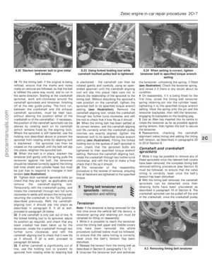 60
60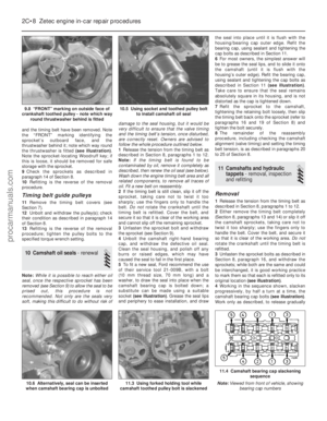 61
61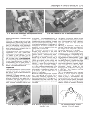 62
62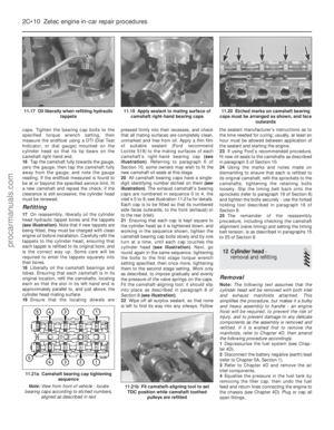 63
63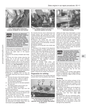 64
64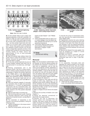 65
65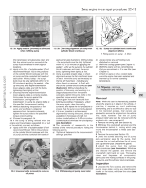 66
66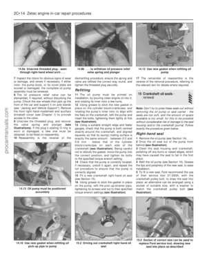 67
67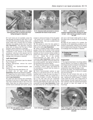 68
68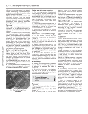 69
69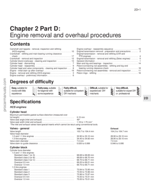 70
70 71
71 72
72 73
73 74
74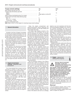 75
75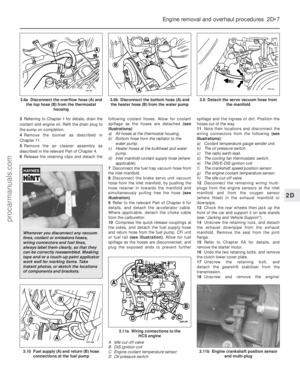 76
76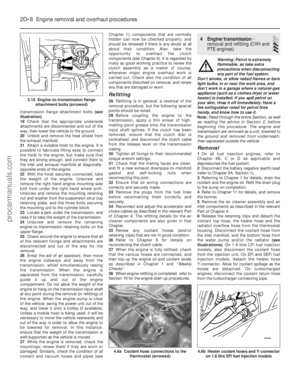 77
77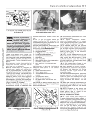 78
78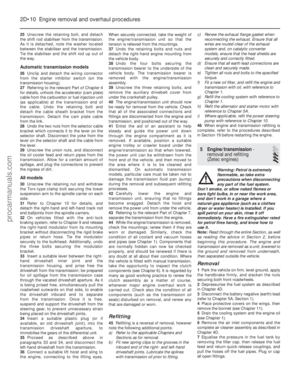 79
79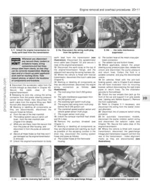 80
80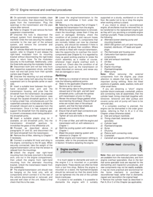 81
81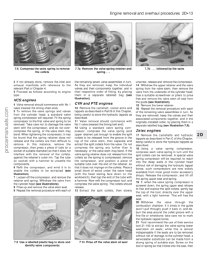 82
82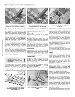 83
83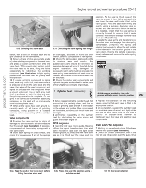 84
84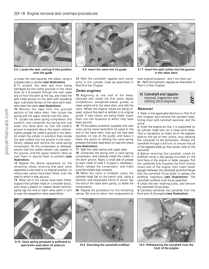 85
85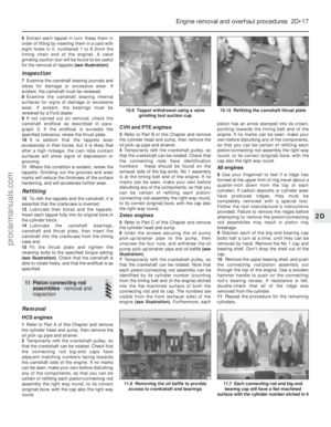 86
86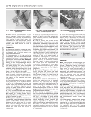 87
87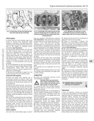 88
88 89
89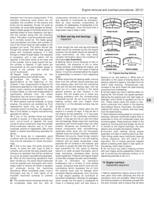 90
90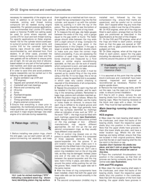 91
91 92
92 93
93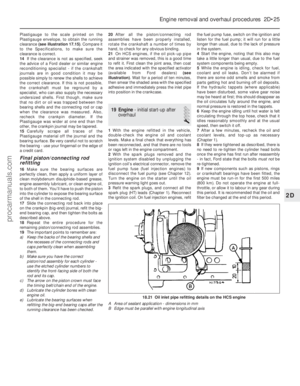 94
94 95
95 96
96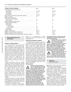 97
97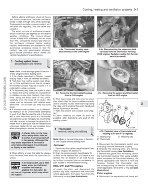 98
98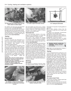 99
99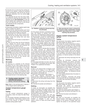 100
100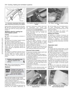 101
101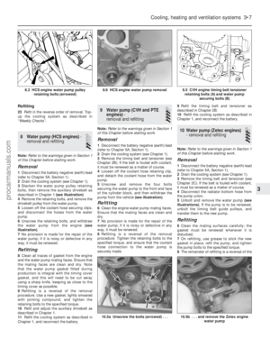 102
102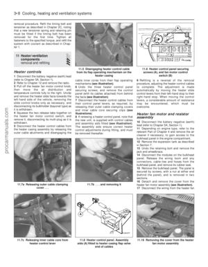 103
103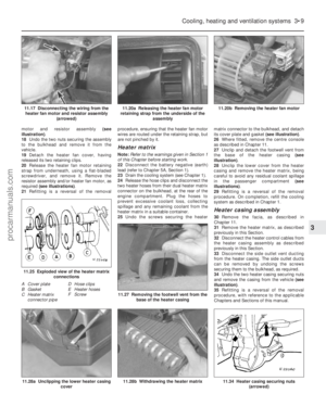 104
104 105
105 106
106 107
107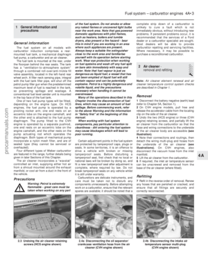 108
108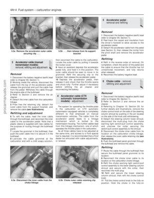 109
109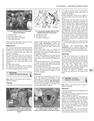 110
110 111
111 112
112 113
113 114
114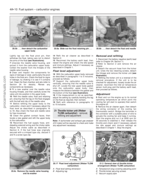 115
115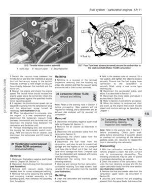 116
116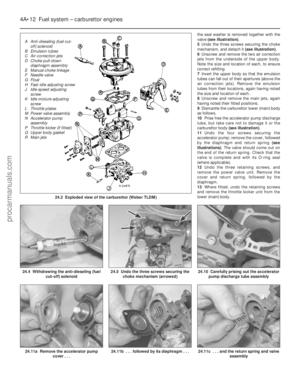 117
117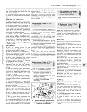 118
118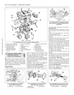 119
119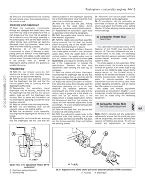 120
120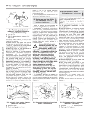 121
121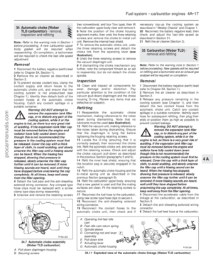 122
122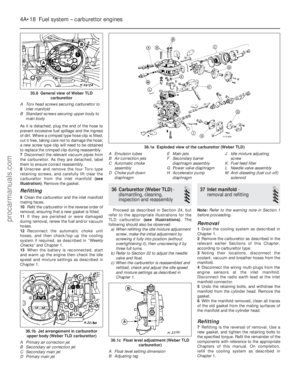 123
123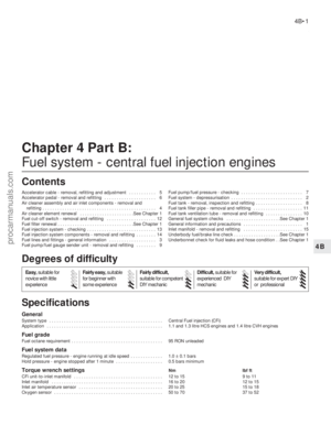 124
124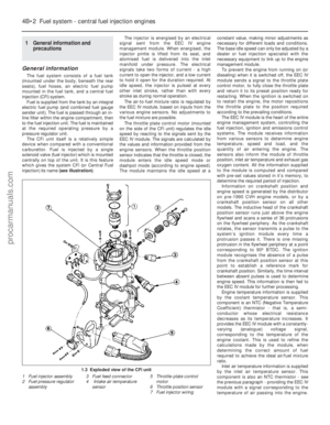 125
125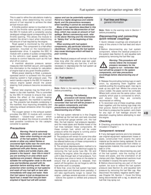 126
126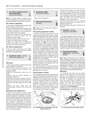 127
127 128
128 129
129 130
130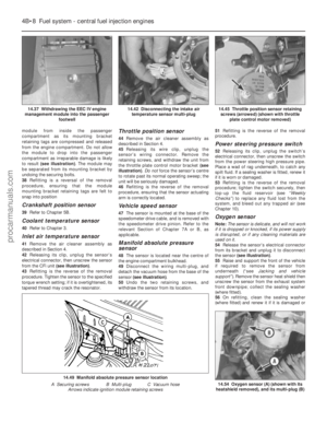 131
131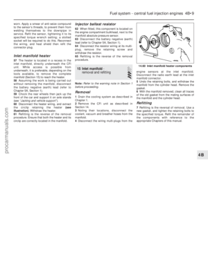 132
132 133
133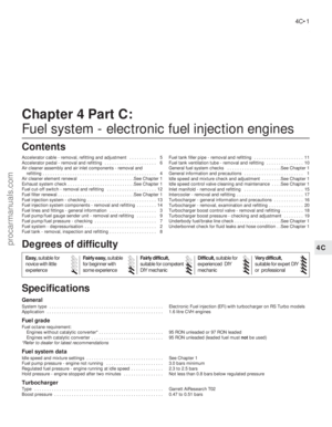 134
134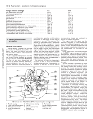 135
135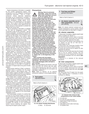 136
136 137
137 138
138 139
139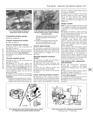 140
140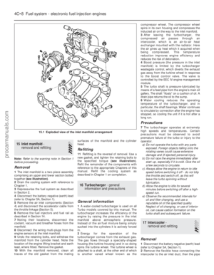 141
141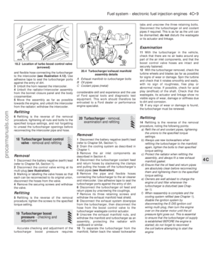 142
142 143
143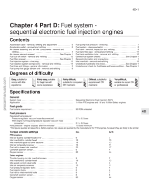 144
144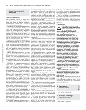 145
145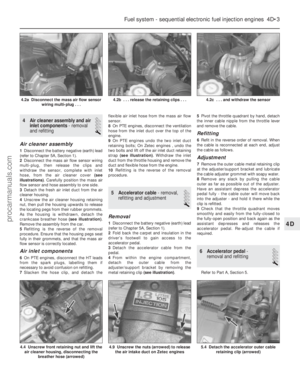 146
146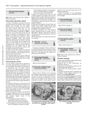 147
147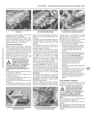 148
148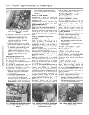 149
149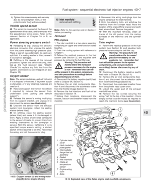 150
150 151
151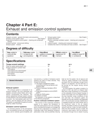 152
152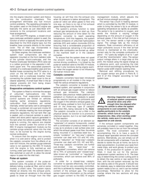 153
153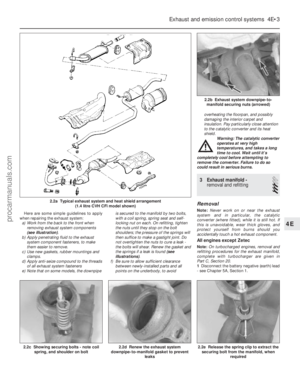 154
154 155
155 156
156 157
157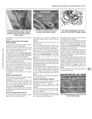 158
158 159
159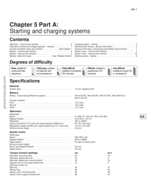 160
160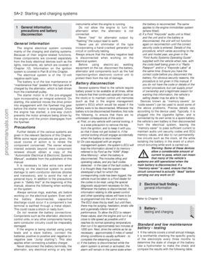 161
161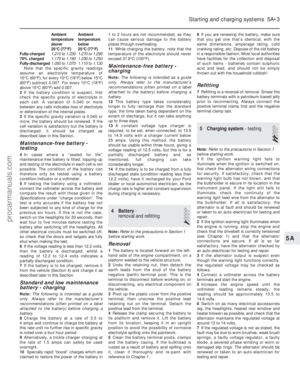 162
162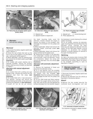 163
163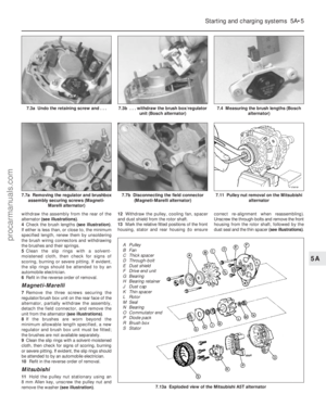 164
164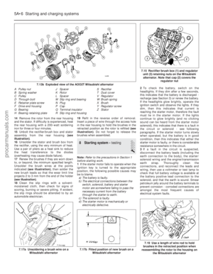 165
165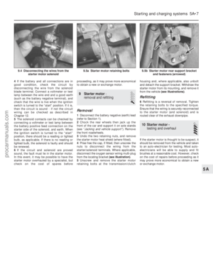 166
166 167
167 168
168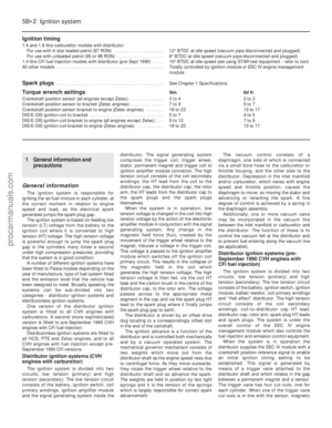 169
169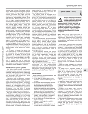 170
170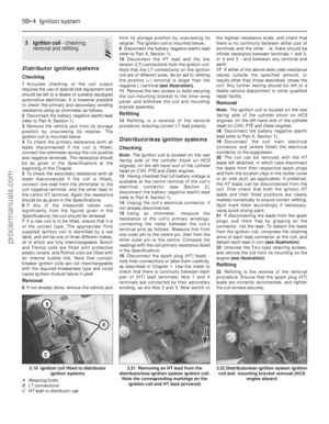 171
171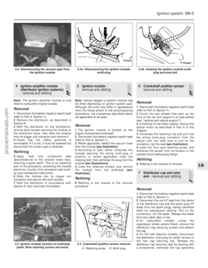 172
172 173
173 174
174 175
175 176
176 177
177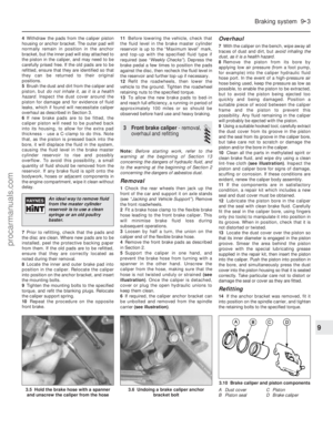 178
178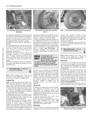 179
179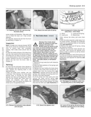 180
180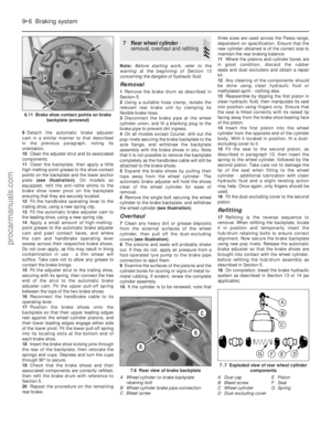 181
181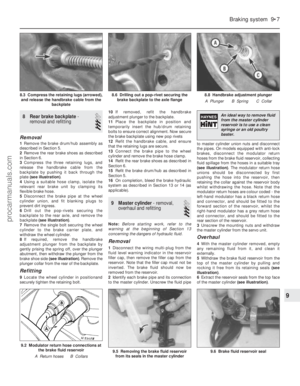 182
182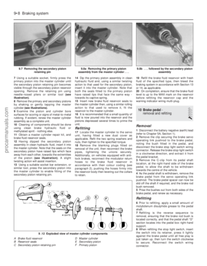 183
183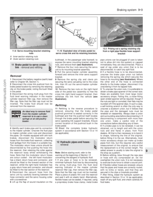 184
184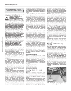 185
185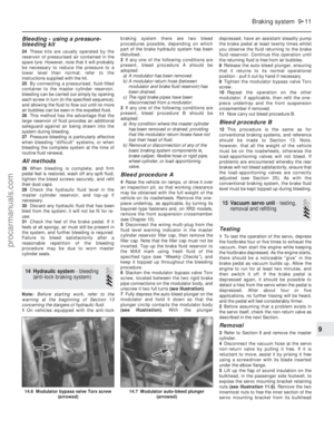 186
186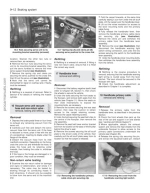 187
187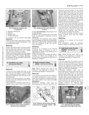 188
188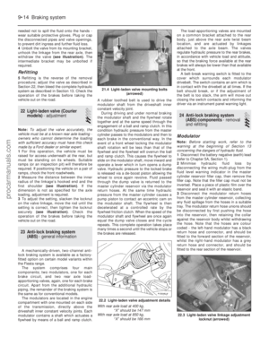 189
189 190
190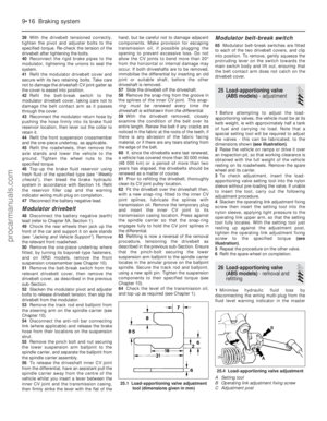 191
191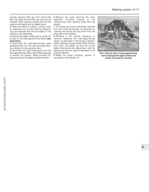 192
192 193
193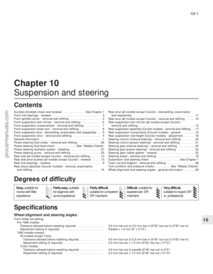 194
194 195
195 196
196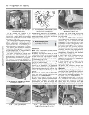 197
197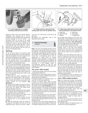 198
198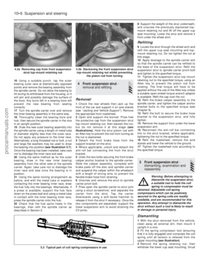 199
199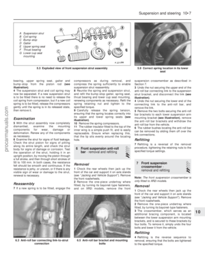 200
200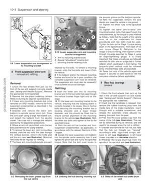 201
201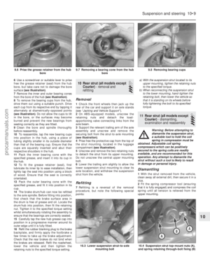 202
202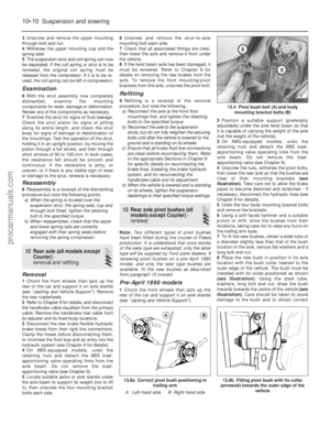 203
203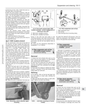 204
204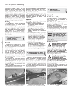 205
205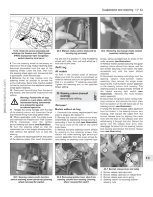 206
206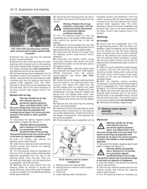 207
207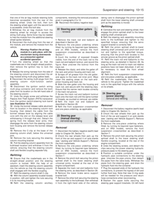 208
208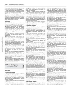 209
209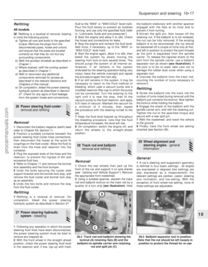 210
210 211
211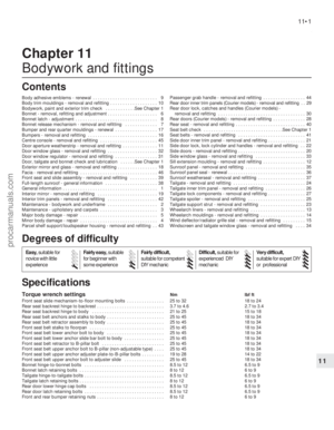 212
212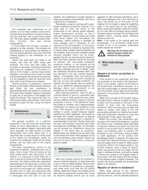 213
213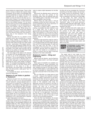 214
214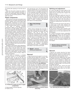 215
215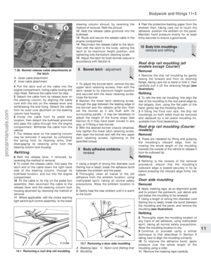 216
216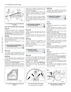 217
217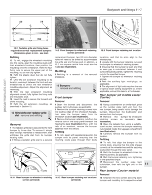 218
218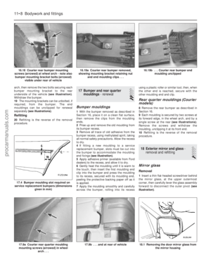 219
219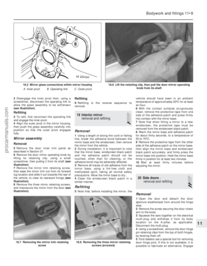 220
220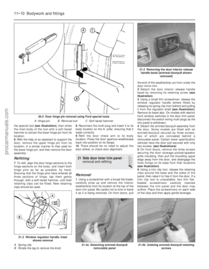 221
221 222
222 223
223 224
224 225
225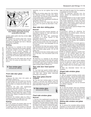 226
226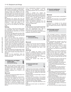 227
227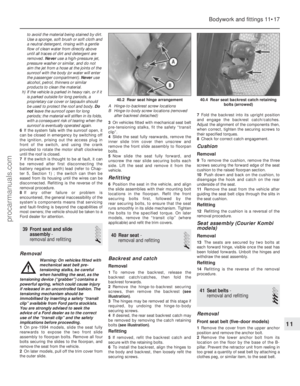 228
228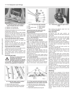 229
229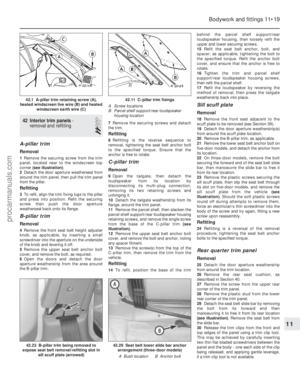 230
230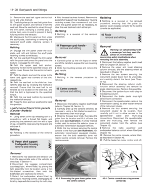 231
231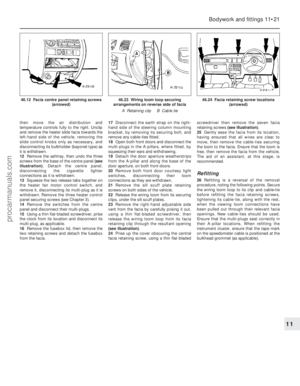 232
232 233
233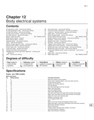 234
234 235
235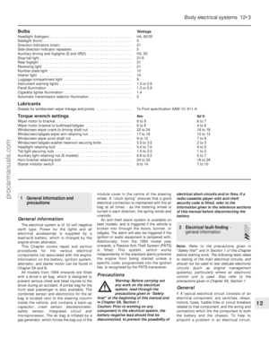 236
236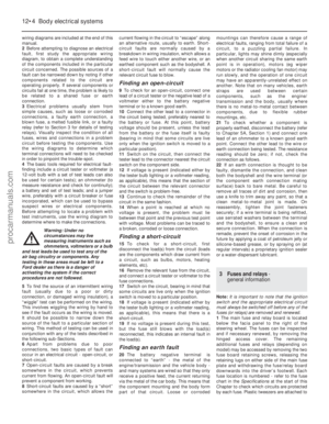 237
237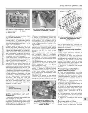 238
238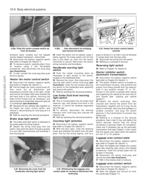 239
239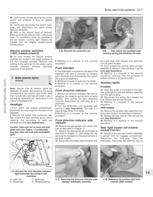 240
240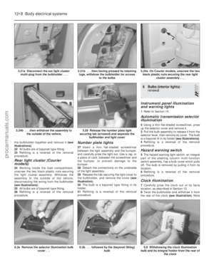 241
241 242
242 243
243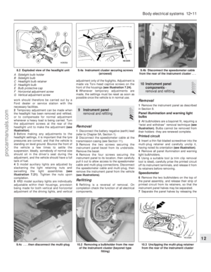 244
244 245
245 246
246 247
247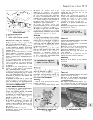 248
248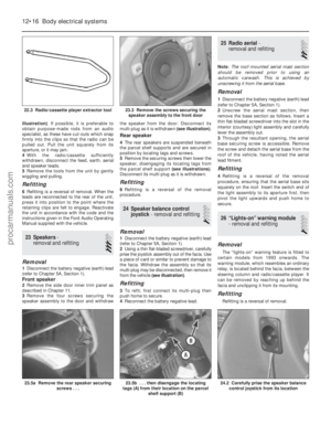 249
249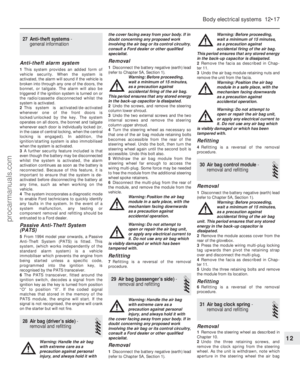 250
250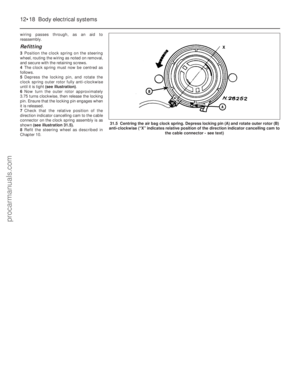 251
251 252
252 253
253 254
254 255
255 256
256 257
257 258
258 259
259 260
260 261
261 262
262 263
263 264
264 265
265 266
266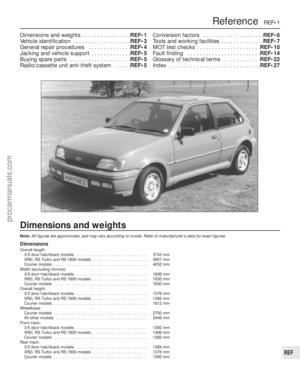 267
267 268
268 269
269 270
270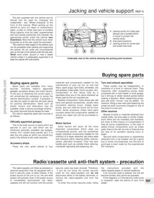 271
271 272
272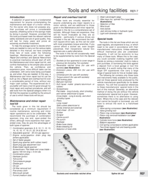 273
273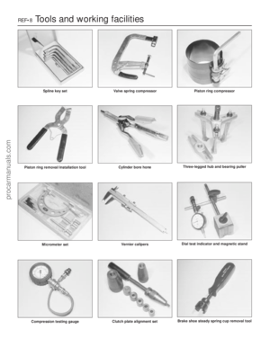 274
274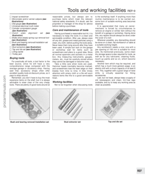 275
275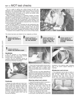 276
276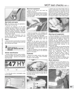 277
277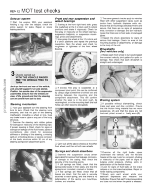 278
278 279
279 280
280 281
281 282
282 283
283 284
284 285
285 286
286 287
287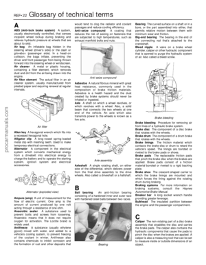 288
288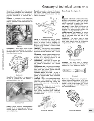 289
289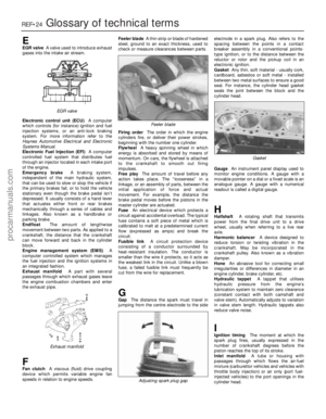 290
290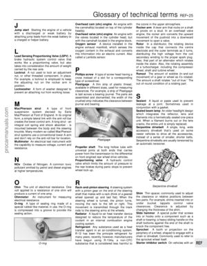 291
291 292
292 293
293 294
294 295
295