Page 25 of 296
 .")
engine idling, the hot-air inlet is open to allow
warm air from the exhaust manifold area to
enter the air cleaner. If the flap operates as
described, it is functioning correctly (see
illustration) .
21 If the flap fails to operate as described,
check the condition of the vacuum pipe and
its connections, and check that the flap valve
has not seized. If these are in order, either the
temperature sensor or vacuum actuator is
faulty, and a new air cleaner assembly must
be obtained. Refit the main air duct on
completion.
25 Emission control system
check
1
General
1Of the emission control systems that may
be fitted, only the crankcase ventilation
system and the evaporative emission control
systems require regular checking, and even
then, the components of these systems
require minimal attention.
2 Should it be felt that the other systems are
not functioning correctly, the advice of a
dealer should be sought.
Crankcase ventilation system
3 The function of the crankcase ventilation
system is to reduce the emission of unburned
hydrocarbons from the crankcase, and to
minimise the formation of oil sludge. By
ensuring that a depression is created in the
crankcase under most operating conditions,
particularly at idle, and by positively inducing
fresh air into the system, the oil vapours and
“blow-by” gases collected in the crankcase
are drawn from the crankcase, through the air
cleaner or oil separator, into the inlet tract, to
be burned by the engine during normal
combustion.
4 On HCS engines, the system consists of a
vented oil filler cap (with an integral mesh
filter) and a hose connecting it to the oil
separator/engine breather valve connector on
the underside of the air cleaner housing. A further hose leads from the adapter/filter to
the inlet manifold.
5
On CVH engines, a closed-circuit type
crankcase ventilation system is used, the
function of which is basically the same as that
described for the HCS engine types, but the
breather hose connects directly to the rocker
cover. A separate filter is fitted in the hose to
the rocker cover in certain applications (see
illustration) .
6 The system fitted to the PTE engines is
similar to that used on the earlier (CVH)
engines on which these engines are based,
but with revisions to the hose arrangement to
suit the remotely sited air cleaner and fuel
injection system layout.
7 On Zetec engines, the crankcase ventilation
system main components are the oil
separator mounted on the front (radiator) side
of the cylinder block/crankcase, and the
Positive Crankcase Ventilation (PCV) valve set
in a rubber grommet in the separator’s left-
hand upper end. The associated pipework
consists of a crankcase breather pipe and two
flexible hoses connecting the PCV valve to a
union on the left-hand end of the inlet
manifold, and a crankcase breather hose
connecting the cylinder head cover to the air
cleaner assembly. A small foam filter in the
air cleaner prevents dirt from being drawn
directly into the engine.
8 Check that all components of the system
are securely fastened, correctly routed (with
no kinks or sharp bends to restrict flow) and in
sound condition; renew any worn or damaged
components.
9 On HCS engines, remove and inspect the
oil filler cap to ensure that it is in good
condition, and not blocked up with sludge.
10 Disconnect the hoses at the cap, and
clean the cap if necessary by brushing the
inner mesh filter with petrol, and blowing
through with light pressure from an air line.
Renew the cap if it is badly congested.
11 If oil leakage is noted, disconnect the
various hoses and pipes, and check that all
are clear and unblocked. Remove the air
cleaner lid, and check that the hose from the
cylinder head cover to the air cleaner housing
is clear and undamaged. 12
Where fitted, the PCV valve is designed to
allow gases to flow out of the crankcase only,
so that a depression is created in the
crankcase under most operating conditions,
particularly at idle. Therefore, if either the oil
separator or the PCV valve are thought to be
blocked, they must be renewed (see Chap-
ter 4E). In such a case, however, there is
nothing to be lost by attempting to flush out
the blockage using a suitable solvent. The
PCV valve should rattle when shaken.
13 While the air filter element is removed (see
Section 24), wipe out the housing, and on
Zetec engines, withdraw the small foam filter
from its location in the rear right-hand corner
of the housing (see illustration) . If the foam is
badly clogged with dirt or oil, it must be
cleaned by soaking it in a suitable solvent,
and allowed to dry before being refitted.
Evaporative emission control
systems
14 Refer to the checks contained in Chap-
ter 4E.
26 Automatic transmission fluid renewal
1
1The automatic transmission fluid should
only be changed when the transmission is
cold.
2 Position the vehicle over an inspection pit,
on vehicle ramps, or jack it up and securely
support it on axle stands, but make sure that
it is level.
3 Place a suitable container beneath the drain
plug on the transmission sump pan. Remove
the transmission fluid dipstick to speed up the
draining operation.
4 Thoroughly clean the area around the drain
plug in the transmission sump pan, then
unscrew the plug and allow the fluid to drain
into the container.
5 When all the fluid has drained (this may take
quite some time) clean the drain plug, then
refit it together with a new seal and tighten it
securely.
6 Place a funnel with a fine mesh screen in
the dipstick tube, and fill the transmission with
1•24Every 30 000 miles or three years
25.13 The crankcase ventilation system foam filter is located in the air cleaner housing on Zetec engines25.5 Crankcase ventilation system filter on CVH engines
24.20 Air cleaner inlet and flap valve onthe CVH engine
A Flap open (cool air inlet closed)
B Warm air inlet
1595Ford Fiesta Remakeprocarmanuals.com
http://vnx.su
Page 26 of 296

the specified type of fluid. It is essential that
no dirt is introduced into the transmission
during this operation.
7Depending on the extent to which the fluid
was allowed to drain, it is possible that the
amount of fluid required when filling the
transmission may be more than the specified
amount (see “Lubricants, fluids and tyre
pressures” ). However, due to fluid remaining in
the system, it is more likely that less than the
specified amount will be required. Add about
half the specified amount, then run the engine
up to its normal operating temperature and
check the level on the dipstick. When the level
approaches the maximum mark, proceed as
detailed in Section 20 to check the level and
complete the final topping-up as described.
27 Handbrake adjustment
3
1 Chock the front wheels then jack up the
rear of the car and support it on axle stands
(see “Jacking and Vehicle Support” ). Fully
release the handbrake.
2 Check that the handbrake cables are
correctly routed and secured by the retaining
clips at the appropriate points under the vehicle.
3 The handbrake is checked for adjustment
by measuring the amount of movement
possible in the handbrake adjuster plungers.
These are located on the inside face of each
rear brake backplate (see illustration) . Thetotal movement of the two plungers combined
should be between 0.5 and 2.0 mm. If the
movement measured is outside of this
tolerance, the handbrake is in need of
adjustment. Adjustment is made altering the
position of the in-line cable adjuster sleeve.
4
When adjustment to the handbrake is
necessary, a new adjustment sleeve locking
pin will be required, and this must therefore
be obtained before making the adjustment.
5 To adjust the handbrake, first ensure that it
is fully released, then firmly apply the
footbrake a few times to ensure that the rear
brake adjustment is taken up by the automatic
adjusters. Extract the locking pin from
the adjuster sleeve (see illustration), then
turn the sleeve to set the combined move-
ment of the plungers within the tolerance range specified (0.5 to 2.0 mm). Turn the
locking nut by hand as tight as is possible
(two clicks) against the adjustment sleeve.
Now grip the locknut with a suitable wrench,
and turn it a further two clicks (maximum).
6
Secure the adjustment by inserting the new
lock pin.
7 Check that the operation of the handbrake
is satisfactory, then lower the vehicle to the
ground, apply the handbrake and remove the
chocks from the front wheels.
28 Front wheel alignment check
4
Refer to Chapter 10, Section 29.
Every 30 000 miles or three years1•25
27.5 Handbrake cable adjuster locking
pin (A), locknut (B) and adjuster sleeve (C)27.3 Handbrake adjustment plunger
located on the inside face of each rear brake backplate
1
1595Ford Fiesta Remake
Every 40 000 miles
29 Timing belt renewal
4
Refer to Chapter 2, Part B or C as
applicable.
Every 60 000 miles
30 Fuel filter renewal
1
Warning: Petrol is extremely
flammable, so extra precautions
must be taken when working on
any part of the fuel system. Do
not smoke, or allow open flames or bare
light bulbs, near the work area. Also, do
not work in a garage if a natural gas-type appliance with a pilot light is present.
While performing any work on the fuel system, wear safety glasses, and have a
suitable (Class B) fire extinguisher on
hand. If you spill any fuel on your skin,
rinse it off immediately with soap and
water.
1
On fuel injection engines, an in-line fuel
filter is provided in the fuel pump outlet line.
The filter is located in the engine compartment
either below and behind the battery, or on the
left-hand side of the engine compartment
bulkhead. The renewal procedure is the same
for both locations. The filter performs a vital
role in keeping dirt and other foreign matter
out of the fuel system, and so must be renewed at regular intervals, or whenever you
have reason to suspect that it may be
clogged. It is always unpleasant working
under a vehicle - pressure-washing or hosing
clean the underbody in the filter’s vicinity will
make working conditions more tolerable, and
will reduce the risk of getting dirt into the fuel
system.
2
Depressurise the fuel system as described
in the relevant Part of Chapter 4.
3 Disconnect the battery negative (earth) lead
(refer to Chapter 5A, Section 1), then position
a suitable container beneath the fuel filter to
catch escaping fuel. Have a rag handy to soak
procarmanuals.com
http://vnx.su
Page 27 of 296

up the fuel when the feed and outlet pipe
unions are disconnected.
4On models without quick-release couplings
on the fuel lines, slowly slacken the fuel feed
pipe union allowing the pressure in the fuel
pipe to reduce. When the pressure is fully
released, disconnect the fuel feed and outlet
pipe unions.
5 On models with quick-release couplings on
the fuel lines, release the fuel feed and outlet
pipe unions from the filter, by squeezing
together the protruding locking lugs on each
union, and carefully pulling the union off the
filter stub (see illustration) . Where the unions are colour-coded, the feed and outlet pipes
cannot be confused; where both unions are
the same colour, note carefully which pipe is
connected to which filter stub, and ensure that
they are correctly reconnected on refitting.
6
Noting the arrows and/or other markings on
the filter showing the direction of fuel flow
(towards the engine), slacken the filter clamp
bolt and withdraw the filter from the car (see
illustrations) . Note that the filter will still
contain fuel; care should be taken, to avoid
spillage and to minimise the risk of fire.
7 On installation, slide the filter into its clamp
so that the arrow marked on it faces the correct way, then reconnect and tighten the
pipe unions or slide each pipe union on to its
(correct) respective filter stub, and press it
down until the locking lugs click into their
groove. Tighten the clamp bolt carefully, until
the filter is just prevented from moving; do not
overtighten, or the filter casing may be
crushed.
8
Refit the fuel pump fuse and reconnect the
battery earth terminal, then switch the ignition
on and off five times, to pressurise the
system. Check for any sign of fuel leakage
around the filter unions before lowering the
vehicle to the ground and starting the engine.
1•26Every 60 000 miles
30.6b Removing the bulkhead mounted fuel filter. Clamp bolt (arrowed)30.6a Fuel filter location below battery
showing clamp bolt (arrowed). Note fuel flow direction arrows on filter body30.5 Releasing the fuel pipe unions fromthe filter on models with quick-release couplings
1595Ford Fiesta Remake
Every 3 years
31 Brake fluid renewal
3
The procedure is similar to that for the
bleeding of the hydraulic system as described
in Chapter 9, except that the brake fluid
reservoir should be emptied by syphoning,
and allowance should be made for the old
fluid to be removed from the circuit when
bleeding a section of the circuit.
procarmanuals.com
http://vnx.su
Page 28 of 296

2A
1595Ford Fiesta Remake
General
Engine type . . . . . . . . . . . . . . . . . . . . . . . . . . . . . . . . . . . .\
. . . . . . . . . . . Four-cylinder, in-line overhead valve
Engine code:1.0 litre carburettor models . . . . . . . . . . . . . . . . . . . . . . . . . . . . . . . . . TLB
1.1 litre carburettor models . . . . . . . . . . . . . . . . . . . . . . . . . . . . . . . . . GUE or GUD
1.1 litre CFi fuel injection models . . . . . . . . . . . . . . . . . . . . . . . . . . . . G6A
1.3 litre carburettor models . . . . . . . . . . . . . . . . . . . . . . . . . . . . . . . . . JBC
1.3 litre CFi fuel injection models . . . . . . . . . . . . . . . . . . . . . . . . . . . . J6B
Capacity: 1.0 litre models . . . . . . . . . . . . . . . . . . . . . . . . . . . . . . . . . . . .\
. . . . . . 999 cc
1.1 litre models . . . . . . . . . . . . . . . . . . . . . . . . . . . . . . . . . . . .\
. . . . . . 1118 cc
1.3 litre models . . . . . . . . . . . . . . . . . . . . . . . . . . . . . . . . . . . .\
. . . . . . 1297 cc
Bore:
1.0 and 1.1 litre models . . . . . . . . . . . . . . . . . . . . . . . . . . . . . . . . . . . 68.68 mm
1.3 litre models . . . . . . . . . . . . . . . . . . . . . . . . . . . . . . . . . . . .\
. . . . . . 73.96 mm
Stroke:
1.0 litre models . . . . . . . . . . . . . . . . . . . . . . . . . . . . . . . . . . . .\
. . . . . . 67.40 mm
1.1 and 1.3 litre models . . . . . . . . . . . . . . . . . . . . . . . . . . . . . . . . . . . 75.48 mm
Compression ratio:
Carburettor models . . . . . . . . . . . . . . . . . . . . . . . . . . . . . . . . . . . .\
. . . 9.5:1
CFi fuel injection models . . . . . . . . . . . . . . . . . . . . . . . . . . . . . . . . . . . 8.8:1
Firing order . . . . . . . . . . . . . . . . . . . . . . . . . . . . . . . . . . . .\
. . . . . . . . . . . 1-2-4-3 (No 1 cylinder at timing chain end)
Direction of crankshaft rotation . . . . . . . . . . . . . . . . . . . . . . . . . . . . . . . Clockwise (seen from right-hand side of vehicle)
Valves
Valve clearance (cold): Inlet . . . . . . . . . . . . . . . . . . . . . . . . . . . . . . . . . . . .\
. . . . . . . . . . . . . . . 0.20 mm
Exhaust . . . . . . . . . . . . . . . . . . . . . . . . . . . . . . . . . . . .\
. . . . . . . . . . . . 0.30 mm
Chapter 2 Part A:
HCS engine in-car repair procedures
Auxiliary drivebelt check and renewal . . . . . . . . . . . . . . .See Chapter 1
Compression test - description and interpretation . . . . . . . . . . . . . . 2
Crankshaft oil seals - renewal . . . . . . . . . . . . . . . . . . . . . . . . . . . . . . 14
Crankshaft pulley - removal and refitting . . . . . . . . . . . . . . . . . . . . . 8
Cylinder head - removal and refitting . . . . . . . . . . . . . . . . . . . . . . . . 7
Cylinder head rocker cover - removal and refitting . . . . . . . . . . . . . . 4
Cylinder head rocker gear - removal, inspection and refitting . . . . . 6
Engine oil and filter renewal . . . . . . . . . . . . . . . . . . . . . . .See Chapter 1
Engine oil level check . . . . . . . . . . . . . . . . . . . . . .See
“Weekly Checks”
Engine/transmission mountings - inspection and renewal . . . . . . . . 15 Flywheel - removal, inspection and refitting . . . . . . . . . . . . . . . . . . . 16
General information . . . . . . . . . . . . . . . . . . . . . . . . . . . . . . . . . . . .\
. . 1
Oil pump - dismantling, inspection and reassembly . . . . . . . . . . . . . 13
Oil pump - removal and refitting . . . . . . . . . . . . . . . . . . . . . . . . . . . . 12
Sump - removal and refitting . . . . . . . . . . . . . . . . . . . . . . . . . . . . . . . 11
Timing chain cover - removal and refitting . . . . . . . . . . . . . . . . . . . . 9
Timing chain, sprockets and tensioner - removal, inspection
and refitting . . . . . . . . . . . . . . . . . . . . . . . . . . . . . . . . . . . .\
. . . . . . 10
Top Dead Centre (TDC) for No 1 piston - locating . . . . . . . . . . . . . . 3
Valve clearances - checking and adjustment . . . . . . . . . . . . . . . . . . 5
2A•1
Specifications Contents
Easy, suitable for
novice with little
experience Fairly easy,
suitable
for beginner with
some experience Fairly difficult,
suitable for competent
DIY mechanic
Difficult,
suitable for
experienced DIY
mechanic Very difficult,
suitable for expert DIY
or professional
Degrees of difficulty
54321
procarmanuals.com
http://vnx.su
Page 29 of 296

Lubrication
Engine oil type/specification . . . . . . . . . . . . . . . . . . . . . . . . . . . . . . . . . . See “Lubricants, fluids and tyre pressures”
Engine oil capacity . . . . . . . . . . . . . . . . . . . . . . . . . . . . . . . . . . . .\
. . . . . See “Lubricants, fluids and tyre pressures”
Oil pressure: At idle speed . . . . . . . . . . . . . . . . . . . . . . . . . . . . . . . . . . . .\
. . . . . . . . 0.60 barsAt 2000 rpm . . . . . . . . . . . . . . . . . . . . . . . . . . . . . . . . . . . .\
. . . . . . . . 1.50 bars
Oil pump clearances: Outer rotor-to-body . . . . . . . . . . . . . . . . . . . . . . . . . . . . . . . . . . . .\
. . 0.14 to 0.26 mm
Inner rotor-to-outer rotor . . . . . . . . . . . . . . . . . . . . . . . . . . . . . . . . . . 0.051 to 0.127 mm
Rotor endfloat . . . . . . . . . . . . . . . . . . . . . . . . . . . . . . . . . . . .\
. . . . . . . 0.025 to 0.06 mm
Torque wrench settingsNm lbf ft
Camshaft thrust plate bolts . . . . . . . . . . . . . . . . . . . . . . . . . . . . . . . . . . 5 4
Camshaft sprocket bolt . . . . . . . . . . . . . . . . . . . . . . . . . . . . . . . . . . . .\
. 1813
Crankshaft pulley bolt . . . . . . . . . . . . . . . . . . . . . . . . . . . . . . . . . . . .\
. . . 115 85
Rocker shaft pedestal bolts . . . . . . . . . . . . . . . . . . . . . . . . . . . . . . . . . . 4332
Flywheel bolts . . . . . . . . . . . . . . . . . . . . . . . . . . . . . . . . . . . .\
. . . . . . . . . 6749
Sump: Stage 1 . . . . . . . . . . . . . . . . . . . . . . . . . . . . . . . . . . . .\
. . . . . . . . . . . . 7 5
Stage 2 . . . . . . . . . . . . . . . . . . . . . . . . . . . . . . . . . . . .\
. . . . . . . . . . . . 9 7
Stage 3 (with engine warm) . . . . . . . . . . . . . . . . . . . . . . . . . . . . . . . . 9 7
Oil pressure switch . . . . . . . . . . . . . . . . . . . . . . . . . . . . . . . . . . . .\
. . . . . 1410
Cylinder head bolts (may be re-used once only): Stage 1 . . . . . . . . . . . . . . . . . . . . . . . . . . . . . . . . . . . .\
. . . . . . . . . . . . 3022
Stage 2 . . . . . . . . . . . . . . . . . . . . . . . . . . . . . . . . . . . .\
. . . . . . . . . . . . Angle-tighten a further 90º
Stage 3 . . . . . . . . . . . . . . . . . . . . . . . . . . . . . . . . . . . .\
. . . . . . . . . . . . Angle-tighten a further 90º
Timing chain tensioner . . . . . . . . . . . . . . . . . . . . . . . . . . . . . . . . . . . .\
. . 8 6
Timing chain cover . . . . . . . . . . . . . . . . . . . . . . . . . . . . . . . . . . . .\
. . . . . 9 7
Crankshaft rear oil seal housing . . . . . . . . . . . . . . . . . . . . . . . . . . . . . . . 1813
Rocker cover bolts . . . . . . . . . . . . . . . . . . . . . . . . . . . . . . . . . . . .\
. . . . . 5 4
Oil pump . . . . . . . . . . . . . . . . . . . . . . . . . . . . . . . . . . . .\
. . . . . . . . . . . . . 1813
Oil pump cover . . . . . . . . . . . . . . . . . . . . . . . . . . . . . . . . . . . .\
. . . . . . . . 9 7
Engine mountings: Engine mounting (right-hand):Bolt to body (in wheel arch) . . . . . . . . . . . . . . . . . . . . . . . . . . . . . . 41 to 58 30 to 43
Nut to body (by suspension strut) . . . . . . . . . . . . . . . . . . . . . . . . . . 41 to 58 30 to 43
Bracket to cylinder block . . . . . . . . . . . . . . . . . . . . . . . . . . . . . . . . 54 to 72 40 to 53
Rubber insulator to bracket . . . . . . . . . . . . . . . . . . . . . . . . . . . . . . 71 to 95 52 to 70
Transmission mounting fasteners . . . . . . . . . . . . . . . . . . . . . . . . . . . . Refer to Chapter 7A or 7B
Note: Refer to Part D of this Chapter for remaining torque wrench settings.
2A•2 HCS engine in-car repair procedures
1595Ford Fiesta Remake
1 General information
How to use this Chapter
This Part of Chapter 2 is devoted to repair
procedures possible while the engine is still
installed in the vehicle, and includes only the
Specifications relevant to those procedures.
Similar information concerning the 1.4 and
1.6 litre CVH and PTE engines, and the 1.6
and 1.8 litre Zetec engines, will be found in
Parts B and C of this Chapter respectively.
Since these procedures are based on the
assumption that the engine is installed in the
vehicle, if the engine has been removed from
the vehicle and mounted on a stand, some
of the preliminary dismantling steps outlined
will not apply. Information concerning engine/transmission
removal and refitting, and engine overhaul, can
be found in Part D of this Chapter, which also
includes the Specifications relevant to those
procedures.
Engine description
The engine is an overhead valve, water-
cooled, four cylinder in-line design,
designated HCS (High Compression Swirl).
The engine is mounted transversely at the
front of the vehicle together with the
transmission to form a combined power unit. The crankshaft is supported in three or five
shell-type main bearings. The connecting rod
big-end bearings are also split shell-type, and
are attached to the pistons by interference-fit
gudgeon pins. Each piston is fitted with two
compression rings and one oil control ring. The camshaft, which runs on bearings
within the cylinder block, is chain-driven from
the crankshaft, and operates the valves via
pushrods and rocker arms. The valves are
each closed by a single valve spring, and
operate in guides integral in the cylinder head. The oil pump is mounted externally on the
crankcase, incorporates a full-flow oil filter,
and is driven by a skew gear on the camshaft.
On carburettor versions, the fuel pump is also
driven from the camshaft, via an eccentric
lobe.
Repair operations possible with
the engine in the car
The following work can be carried out with
the engine in the car:
a) Compression pressure - testing.
b) Cylinder head rocker cover - removal
and refitting.
c) Valve clearances - adjustment.
d) Rocker shaft assembly - removal,
inspection and refitting.
e) Cylinder head - removal and refitting
f) Cylinder head and pistons - decarbonising.
g) Crankshaft pulley - removal and refitting.
h) Crankshaft oil seals - renewal.
i) Timing chain, sprockets and tensioner -
removal, inspection and refitting.
j) Oil filter renewal.
k) Oil pump - removal and refitting.
l) Sump - removal and refitting.
m) Flywheel - removal, inspection and
refitting.
n) Engine/transmission mountings -
inspection and renewal.
Note: It is possible to remove the pistons and
procarmanuals.com
http://vnx.su
Page 30 of 296
 without removing the engine.
However, this is not recommended. Work of
this nature is more easily and thoroughly
completed with the engine o")
connecting rods (after removing the cylinder
head and sump) without removing the engine.
However, this is not recommended. Work of
this nature is more easily and thoroughly
completed with the engine on the bench, as
described in Chapter 2D.
2 Compression test-
description and interpretation
2
1 When engine performance is down, or if
misfiring occurs which cannot be attributed to
the ignition or fuel systems, a compression
test can provide diagnostic clues as to the
engine’s condition. If the test is performed
regularly, it can give warning of trouble before
any other symptoms become apparent.
2 The engine must be fully warmed-up to
normal operating temperature, the oil level
must be correct and the battery must be fully
charged. The aid of an assistant will also be
required.
3 On fuel injection engines, refer to Chap-
ter 12 and remove the fuel pump fuse from the
fusebox. Now start the engine and allow it to
run until it stalls.
4 Disable the ignition system by
disconnecting the multi-plug from the DIS or
E-DIS ignition coil. Remove all the spark plugs
with reference to Chapter 1 if necessary.
5 Fit a compression tester to the No 1
cylinder spark plug hole - the type of tester
which screws into the plug thread is to be
preferred.
6 Arrange for an assistant to hold the
accelerator pedal fully depressed to the floor,
while at the same time cranking the engine
over for several seconds on the starter motor.
Observe the compression gauge reading. The
compression will build up fairly quickly in a
healthy engine. Low compression on the first
stroke, followed by gradually-increasing
pressure on successive strokes, indicates
worn piston rings. A low compression on the
first stroke which does not rise on successive
strokes, indicates leaking valves or a blown
head gasket (a cracked cylinder head could
also be the cause). Deposits on the underside
of the valve heads can also cause low
compression. Record the highest gauge
reading obtained, then repeat the procedure
for the remaining cylinders.
7 Due to the variety of testers available, and
the fluctuation in starter motor speed when
cranking the engine, different readings
are often obtained when carrying out
the compression test. For this reason, actual
compression pressure figures are not quoted
by Ford. However, the most important factor
is that the compression pressures are uniform
in all cylinders, and that is what this test is
mainly concerned with.
8 Add some engine oil (about three squirts
from a plunger type oil can) to each cylinder
through the spark plug holes, and then repeat
the test. 9
If the compression increases after the oil is
added, it is indicative that the piston rings are
definitely worn. If the compression does not
increase significantly, the leakage is occurring
at the valves or the head gasket. Leakage
past the valves may be caused by burned
valve seats and/or faces, or warped, cracked
or bent valves.
10 If two adjacent cylinders have equally low
compressions, it is most likely that the head
gasket has blown between them. The
appearance of coolant in the combustion
chambers or on the engine oil dipstick would
verify this condition.
11 If one cylinder is about 20 percent lower
than the other, and the engine has a slightly
rough idle, a worn lobe on the camshaft could
be the cause.
12 On completion of the checks, refit the
spark plugs and reconnect the HT leads and
the ignition coil plug. Refit the fuel pump fuse
to the fusebox.
3 Top Dead Centre (TDC) for No 1 piston - locating
2
1Top dead centre (TDC) is the highest point
of the cylinder that each piston reaches as the
crankshaft turns. Each piston reaches its TDC
position at the end of its compression stroke,
and then again at the end of its exhaust
stroke. For the purpose of engine timing, TDC
at the end of the compression stroke for No 1
piston is used. On the HCS engine, No 1
cylinder is at the crankshaft pulley/timing
chain end of the engine. Proceed as follows.
2 Ensure that the ignition is switched off.
Disconnect the HT leads from the spark plugs,
then unscrew and remove the plugs as
described in Chapter 1.
3 Turn the engine over by hand (using a
spanner on the crankshaft pulley) to the point
where the timing mark on the crankshaft
pulley aligns with the TDC (0) mark or TDC
reference pointer on the timing cover (see
illustration) . As the pulley mark nears the
timing mark, the No 1 piston is simultaneously
approaching the top of its cylinder. To ensure
that it is on its compression stroke, place a
finger over the No 1 cylinder plug hole, and feel to ensure that air pressure exits from the
cylinder as the piston reaches the top of its
stroke.
4
A further check to ensure that the piston is
on its compression stroke can be made by
first removing the air cleaner (refer to the
relevant Part of Chapter 4), then unbolting and
removing the rocker cover, so that the
movement of the valves and rockers can be
observed.
5 With the TDC timing marks on the
crankshaft pulley and timing cover in
alignment, rock the crankshaft back and forth
a few degrees each side of this position, and
observe the action of the valves and rockers
for No 1 cylinder. When No 1 piston is at the
TDC firing position, the inlet and exhaust valve
of No 1 cylinder will be fully closed, but the
corresponding valves of No 4 cylinder will be
seen to rock open and closed.
6 If the inlet and exhaust valves of No 1
cylinder are seen to rock whilst those of
No 4 cylinder are shut, the crankshaft will
need to be turned one full rotation to bring
No 1 piston up to the top of its cylinder on the
compression stroke.
7 Once No 1 cylinder has been positioned at
TDC on the compression stroke, TDC for any
of the other cylinders can then be located by
rotating the crankshaft clockwise (in its
normal direction of rotation), 180º at a time,
and following the firing order (see
Specifications).
4 Cylinder head rocker cover -
removal and refitting
1
Removal
1 Where necessary for access, remove the air
cleaner as described in the relevant Part of
Chapter 4.
2 Detach the HT leads from the spark plugs.
Pull on the connector of each lead (not the
lead itself), and note the order of fitting.
3 Remove the engine oil filler cap and
breather hose (where fitted).
4 Unscrew the four retaining bolts, and lift the
rocker cover clear of the cylinder head.
Remove the gasket.
HCS engine in-car repair procedures 2A•3
3.3 Timing mark on the crankshaft pulley aligned with the TDC (0) mar\
k on the timing cover
2A
1595Ford Fiesta Remakeprocarmanuals.com
http://vnx.su
Page 31 of 296

Refitting
5Thoroughly clean the rocker cover, and
scrape away any traces of old gasket
remaining on the cover and cylinder head
mating surfaces.
6 Fit a new gasket to the rocker cover, then
refit the rocker cover (see illustrations).
Tighten the cover retaining bolts to the
specified torque wrench setting, in a diagonal
sequence.
7 Reconnect the HT leads, and refit the air
cleaner as described in Chapter 4.
5 Valve clearances -
checking and adjustment
2
Note: The valve clearances must be checked
and adjusted only when the engine is cold.
1 The importance of having the valve
clearances correctly adjusted cannot be
overstressed, as they vitally affect the
performance of the engine. If the clearances
are too big, the engine will be noisy
(characteristic rattling or tapping noises) and
engine efficiency will be reduced, as the
valves open too late and close too early. A
more serious problem arises if the clearances
are too small, however. If this is the case, the
valves may not close fully when the engine is
hot, resulting in serious damage to the engine
(eg. burnt valve seats and/or cylinder head
warping/cracking). The clearances are
checked and adjusted as follows.
2 Set the engine to TDC for No 1 piston, as
described in Section 3.
3 Remove the rocker cover as described in
Section 4.
4 Starting from the thermostat end of the
cylinder head, the valves are numbered as
follows: Valve No Cylinder No
1 - Exhaust 1
2 - Inlet 1
3 - Exhaust 2
4 - Inlet 2
5 - Inlet 3
6 - Exhaust 3
7 - Inlet 4
8 - Exhaust 4 5
Adjust the valve clearances following the
sequence given in the following table. Turn
the crankshaft pulley 180º (half a turn) after
adjusting each pair of valve clearances.
Valves “rocking” Valves to adjust
7 and 8 1 (exhaust), 2 (inlet)
5 and 6 3 (exhaust), 4 (inlet)
1 and 2 8 (exhaust), 7 (inlet)
3 and 4 6 (exhaust), 5 (inlet)
6 The clearances for the inlet and exhaust
valves differ (refer to the Specifications). Use a
feeler gauge of the appropriate thickness to
check each clearance between the end of the
valve stem and the rocker arm (see
illustration) . The gauge should be a firm
sliding fit between the valve and rocker arm.
Where adjustment is necessary, turn the
adjuster bolt as required with a ring spanner
to set the clearance to that specified. The
adjuster bolts are of stiff-thread type, and
require no locking nut.
7 On completion, refit the rocker cover as
described in Section 4.
6 Cylinder head rocker gear -
removal, inspection and
refitting
2
Removal
1 Remove the rocker cover as described in
Section 4.
2 Unscrew the four retaining bolts, and lift the
rocker gear assembly from the cylinder head.
As the assembly is withdrawn, ensure that the
pushrods remain seated in their positions in
the engine.
Inspection
3 To dismantle the rocker shaft assembly,
extract the split pin from one end of the shaft,
then withdraw the spring and plain washers
from the shaft.
4 Slide off the rocker arms, the support
pedestals and coil springs from the shaft, but take care to keep them in their original order
of fitting
(see illustration) .
5 Clean the respective components, and
inspect them for signs of excessive wear or
damage. Check that the oil lubrication holes in
the shaft are clear.
6 Check the rocker shaft and arm pads which
bear on the valve stem end faces for wear and
scoring, and check each rocker arm on the
shaft for excessive wear. Renew any
components as necessary.
Refitting
7 Apply clean engine oil to the rocker shaft
prior to reassembling.
2A•4 HCS engine in-car repair procedures
6.4 Rocker shaft partially dismantled for inspection
5.6 Adjusting the valve clearances4.6b Refitting the rocker cover4.6a Engage tags of rocker cover gasketinto the cut-outs in the cover
1595Ford Fiesta Remake
Turning the engine will be
easier if the spark plugs are
removed first - see Chapter 1.
If the pushrods are to be removed,
keep them in the correct order of fitting
by labelling them 1 to 8, starting from
the thermostat end of the cylinder
head, or locate them in a card.
procarmanuals.com
http://vnx.su
Page 32 of 296

8Reassemble in the reverse order of
dismantling. Make sure that the “flat” on the
rear end of the rocker shaft is to the same side
as the rocker arm adjusting screws (closest to
the thermostat end of the cylinder head when
fitted) (see illustration) . This is essential for
the correct lubrication of the cylinder head
components.
9 Refit the rocker shaft assembly. As it is
fitted, ensure that the rocker adjuster screws
engage with their corresponding pushrods.
10 Refit the rocker shaft retaining bolts,
hand-tighten them and then tighten them to
the specified torque wrench setting. As they
are tightened, some of the rocker arms will
apply pressure to the ends of the valve stems,
and some of the rocker pedestals will not
initially be in contact with the cylinder head -
these should pull down as the bolts are
tightened to their specified torque. If for any
reason they do not, avoid the temptation to
overtighten in order to pull them into position;
loosen off the bolts, and check the cause of
the problem. It may be that the rocker adjuster
screws require loosening off in order to allow
the assembly to be tightened down as
required.
11 Adjust the valve clearances as described
in Section 5.
7 Cylinder head -
removal and refitting
3
Removal
Note: The following procedure describes
removal and refitting of the cylinder head
complete with inlet and exhaust manifolds. If
wished, the manifolds may be removed first,
as described in the relevant Part of Chapter 4,
and the cylinder head then removed on its
own.
1 On fuel injection engines, depressurise the
fuel system as described in Chapter 4, Part B.
2 Disconnect the battery negative (earth) lead
(refer to Chapter 5A, Section 1).
3 Refer to Chapter 4A or 4B as applicable
and remove the air cleaner.
4 Refer to Section 4 and remove the rocker
cover. 5
Refer to Chapter 1 and drain the cooling
system.
6 Disconnect the hoses from the thermostat
housing.
7 Disconnect the heater (coolant) hoses from
the inlet manifold and CFi unit, where
applicable.
8 Disconnect the accelerator and choke
cables as applicable (see Chapter 4A or 4B).
9 Disconnect the vacuum and breather hoses
from the carburettor/CFi unit, and inlet
manifold as applicable.
10 Disconnect the fuel feed and return lines
at the carburettor, or at the quick-release
couplings, then unclip the fuel hoses from the
inlet manifold; use rag to soak up any spilt
fuel.
11 Disconnect the HT leads from the spark
plugs and the support bracket. Unscrew and
remove the spark plugs.
12 Disconnect the electrical leads from the
temperature gauge sender, radiator cooling
fan, the engine coolant temperature sender,
and the anti-run-on (anti-dieselling) valve at
the carburettor.
13 Disconnect the remaining wiring multi-
plugs from the engine sensors at the inlet
manifold and from the oxygen sensor (where
fitted) in the exhaust manifold or downpipe.
14 On vehicles equipped with a pulse-air
system, remove the pulse-air piping and filter
assembly as described in Chapter 4E.
15 Chock the rear wheels then jack up the
front of the car and support it on axle stands
(see “Jacking and Vehicle Support” ).
16 Undo the retaining nuts and bolts, and
disconnect the exhaust downpipe from the
manifold. Remove the flange gasket. (Note
that both the gasket and the joint self-locking
nuts must be renewed.) To prevent the
exhaust system from being strained, tie the
downpipe up using strong wire or a length of
cord to support it. Lower the vehicle.
17 Undo the four retaining bolts and lift clear
the rocker gear assembly from the cylinder
head.
18 Lift out the pushrods. Keep them in order
of fitting by labelling them 1 to 8, starting from
the thermostat end of the cylinder head.
Alternatively, push them through a piece of
card in their fitted sequence.
19 Progressively unscrew and loosen off the
cylinder head retaining bolts in the reverse
sequence to that shown for tightening (see
illustration 7.27a). When they are all loosened off, remove the bolts, then lift the
cylinder head clear and remove the gasket. If
it is stuck, tap it upwards using a hammer and
block of wood. Do not try to turn it, as it is
located by dowels; make no attempt
whatsoever to prise it free using a screwdriver
inserted between the block and head faces.
The gasket must always be renewed; it should
be noted that the cylinder head retaining bolts
may be re-used, but only once. They should
be marked accordingly with a punch or paint
mark. If there is any doubt as to how many
times the bolts have been used, they must be
renewed.
20
To dismantle/overhaul the cylinder head,
refer to Part D of this Chapter. It is normal for
the cylinder head to be decarbonised and the
valves to be reground whenever the head is
removed.
Preparation for refitting
21 The mating faces of the cylinder head and
cylinder block must be perfectly clean before
refitting the head. Use a hard plastic or wood
scraper to remove all traces of gasket and
carbon; also clean the piston crowns. Take
particular care during the cleaning operations,
as aluminium alloy is easily damaged. Also,
make sure that the carbon is not allowed to
enter the oil and water passages - this is
particularly important for the lubrication
system, as carbon could block the oil supply
to the engine’s components. Using adhesive
tape and paper, seal the water, oil and bolt
holes in the cylinder block.
22 Check the mating surfaces of the cylinder
block and the cylinder head for nicks, deep
scratches and other damage. If slight, they
may be removed carefully with a file, but if
excessive, machining may be the only
alternative to renewal.
23 If warpage of the cylinder head gasket
surface is suspected, use a straight-edge to
check it for distortion. Refer to Part D of this
Chapter if necessary.
24 Clean the threads of the cylinder head
bolts or fit new ones (as applicable) and clean
out the bolt holes in the block. Screwing a bolt
into an oil-filled hole can (in extreme cases)
cause the block to fracture, due to the
hydraulic pressure.
Refitting
25 Check that the new cylinder head gasket
is the same type as the original, and that the
“TOP” (or “OBEN”) marking is facing
upwards. Locate the new cylinder head
HCS engine in-car repair procedures 2A•5
6.8 Flat on the rocker shaft (arrowed) to
same side as rocker arm adjusting screws
2A
1595Ford Fiesta Remake
Whenever you disconnect
any vacuum lines, coolant or
emissions hoses, wiring
connectors and fuel lines,
always label them clearly, so that they
can be correctly reassembled. Masking
tape and/or a touch-up paint applicator
work well for marking items. Take
instant photos, or sketch the locations
of components and brackets.
To prevent carbon entering
the gap between the pistons
and bores, smear a little
grease in the gap. After
cleaning each piston, use a small brush
to remove all traces of grease and
carbon from the gap, then wipe away
the remainder with a clean rag.
procarmanuals.com
http://vnx.su
 1
1 2
2 3
3 4
4 5
5 6
6 7
7 8
8 9
9 10
10 11
11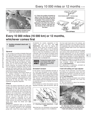 12
12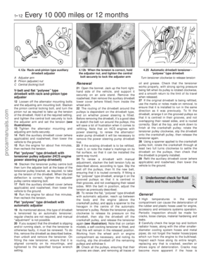 13
13 14
14 15
15 16
16 17
17 18
18 19
19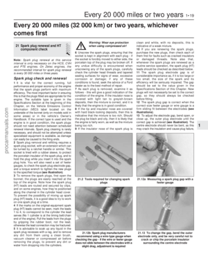 20
20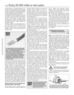 21
21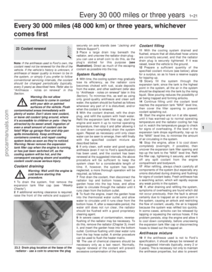 22
22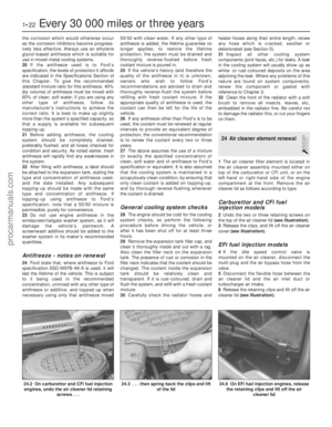 23
23 24
24 25
25 26
26 27
27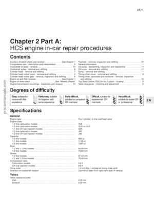 28
28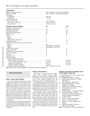 29
29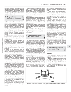 30
30 31
31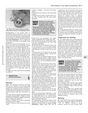 32
32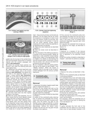 33
33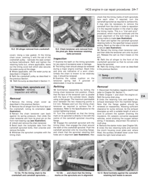 34
34 35
35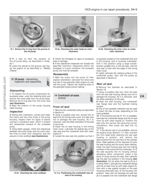 36
36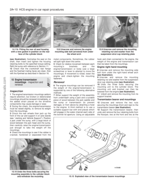 37
37 38
38 39
39 40
40 41
41 42
42 43
43 44
44 45
45 46
46 47
47 48
48 49
49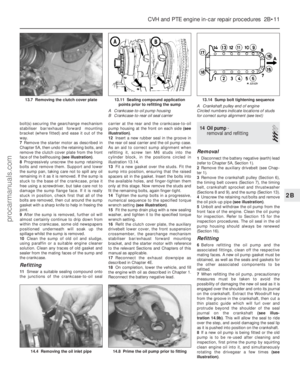 50
50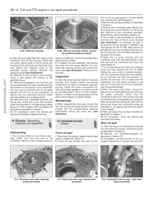 51
51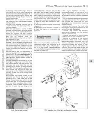 52
52 53
53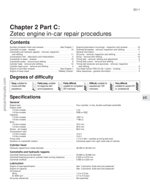 54
54 55
55 56
56 57
57 58
58 59
59 60
60 61
61 62
62 63
63 64
64 65
65 66
66 67
67 68
68 69
69 70
70 71
71 72
72 73
73 74
74 75
75 76
76 77
77 78
78 79
79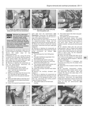 80
80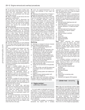 81
81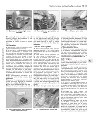 82
82 83
83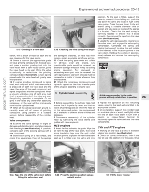 84
84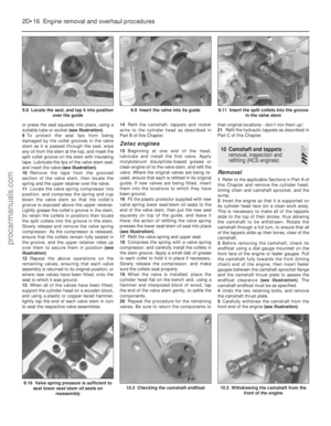 85
85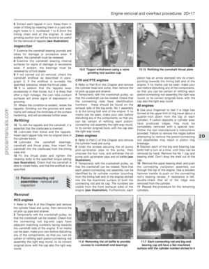 86
86 87
87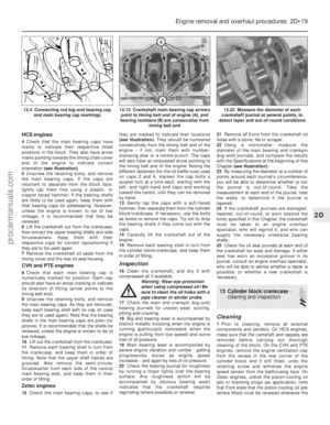 88
88 89
89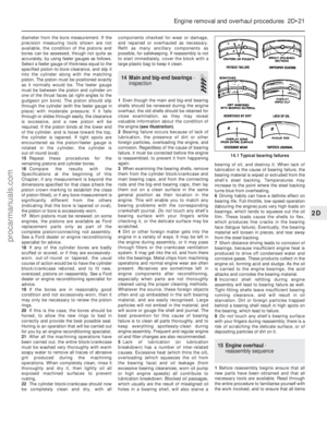 90
90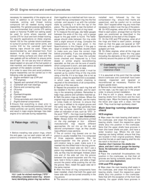 91
91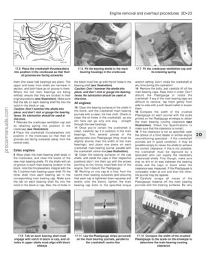 92
92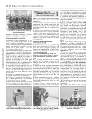 93
93 94
94 95
95 96
96 97
97 98
98 99
99 100
100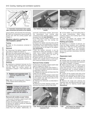 101
101 102
102 103
103 104
104 105
105 106
106 107
107 108
108 109
109 110
110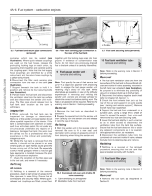 111
111 112
112 113
113 114
114 115
115 116
116 117
117 118
118 119
119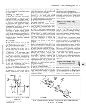 120
120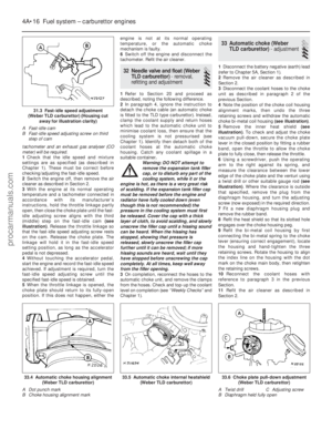 121
121 122
122 123
123 124
124 125
125 126
126 127
127 128
128 129
129 130
130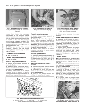 131
131 132
132 133
133 134
134 135
135 136
136 137
137 138
138 139
139 140
140 141
141 142
142 143
143 144
144 145
145 146
146 147
147 148
148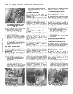 149
149 150
150 151
151 152
152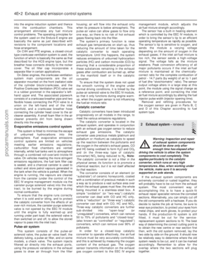 153
153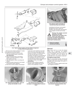 154
154 155
155 156
156 157
157 158
158 159
159 160
160 161
161 162
162 163
163 164
164 165
165 166
166 167
167 168
168 169
169 170
170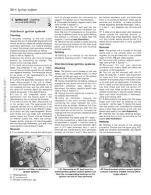 171
171 172
172 173
173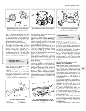 174
174 175
175 176
176 177
177 178
178 179
179 180
180 181
181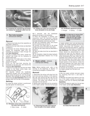 182
182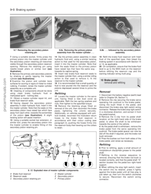 183
183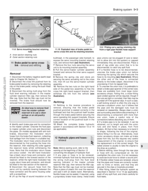 184
184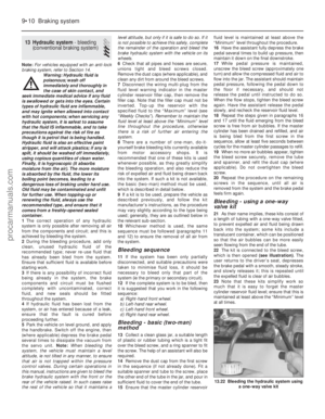 185
185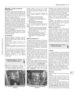 186
186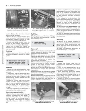 187
187 188
188 189
189 190
190 191
191 192
192 193
193 194
194 195
195 196
196 197
197 198
198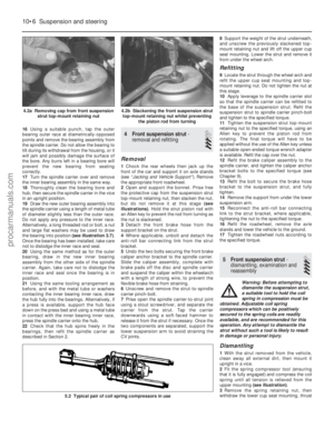 199
199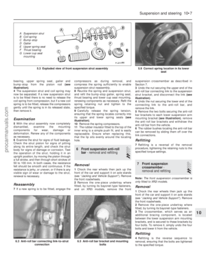 200
200 201
201 202
202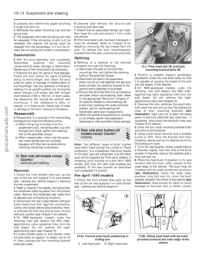 203
203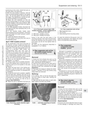 204
204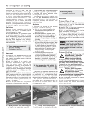 205
205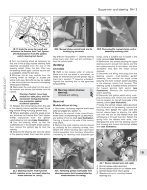 206
206 207
207 208
208 209
209 210
210 211
211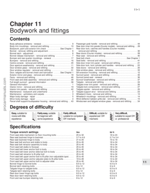 212
212 213
213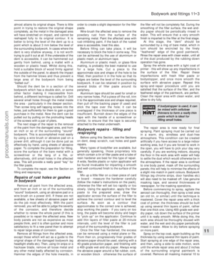 214
214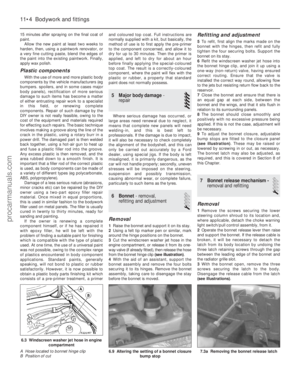 215
215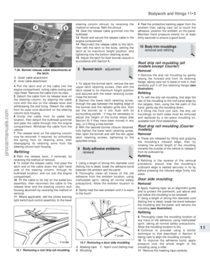 216
216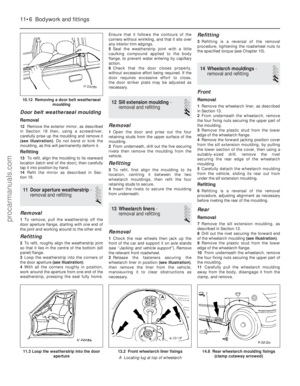 217
217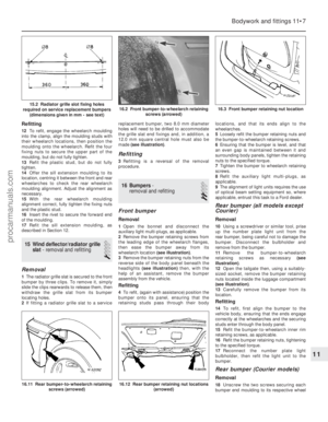 218
218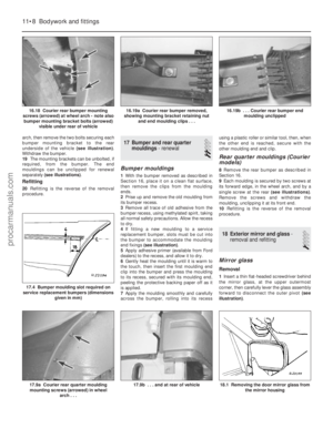 219
219 220
220 221
221 222
222 223
223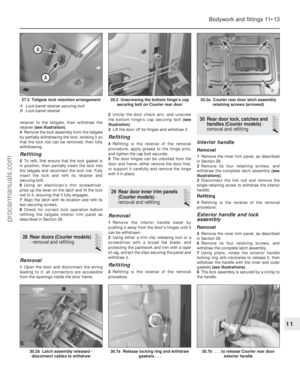 224
224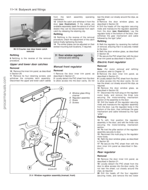 225
225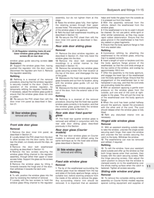 226
226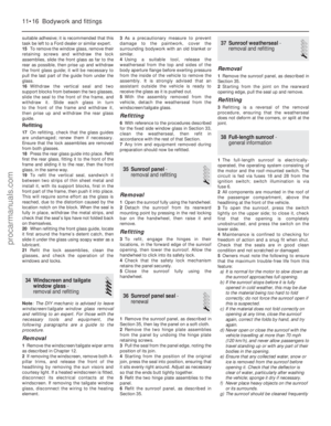 227
227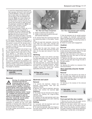 228
228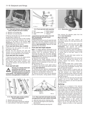 229
229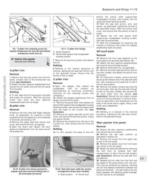 230
230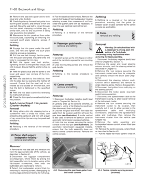 231
231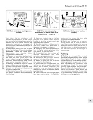 232
232 233
233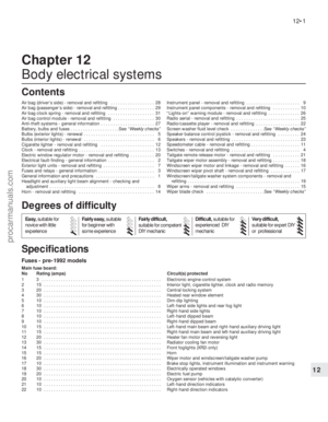 234
234 235
235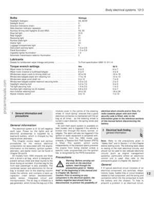 236
236 237
237 238
238 239
239 240
240 241
241 242
242 243
243 244
244 245
245 246
246 247
247 248
248 249
249 250
250 251
251 252
252 253
253 254
254 255
255 256
256 257
257 258
258 259
259 260
260 261
261 262
262 263
263 264
264 265
265 266
266 267
267 268
268 269
269 270
270 271
271 272
272 273
273 274
274 275
275 276
276 277
277 278
278 279
279 280
280 281
281 282
282 283
283 284
284 285
285 286
286 287
287 288
288 289
289 290
290 291
291 292
292 293
293 294
294 295
295