Page 169 of 296
 . . . . . . . . . . . . . . . . . . . . 12°BTDC at idle speed (vacuum pipe disconnect")
Ignition timing
1.4 and 1.6 litre carburettor models with distributor:For use with 4-star leaded petrol (97 RON) . . . . . . . . . . . . . . . . . . . . 12°BTDC at idle speed (vacuum pipe disconnected and plugged)
For use with unleaded petrol (95 or 98 RON) . . . . . . . . . . . . . . . . . . . 8° BTDC at idle speed (vacuum pipe disconnected and plugged)
1.4 litre CFi fuel injection models with distributor (pre-Sept 1990) . . . . 10°BTDC at idle speed (set using STAR test equipment - refer to text)
All other models . . . . . . . . . . . . . . . . . . . . . . . . . . . . . . . . . . . .\
. . . . . . . Totally controlled by ignition module or EEC IV engine management module
Spark plugs . . . . . . . . . . . . . . . . . . . . . . . . . . . . . . . . . . . .\
. . . . . . . See Chapter 1 Specifications
Torque wrench settingsNmlbf ft
Crankshaft position sensor (all engines except Zetec) . . . . . . . . . . . . . . 3 to 4 2 to 3
Crankshaft position sensor to bracket (Zetec engines) . . . . . . . . . . . . . 7 to 9 5 to 7
Crankshaft position sensor bracket to engine (Zetec engines) . . . . . . . 18 to 23 13 to 17
DIS/E-DIS ignition coil to bracket . . . . . . . . . . . . . . . . . . . . . . . . . . . . . . 5 to 7 4 to 5
DIS/E-DIS ignition coil bracket to engine (all engines except Zetec) . . . 9 to 12 7 to 9
DIS/E-DIS ignition coil bracket to engine (Zetec engines) . . . . . . . . . . . 18 to 23 13 to 17
5B•2 Ignition system
1595Ford Fiesta Remake
1 General information and
precautions
General information
The ignition system is responsible for
igniting the air/fuel mixture in each cylinder, at
the correct moment in relation to engine
speed and load, as the electrical spark
generated jumps the spark plug gap. The ignition system is based on feeding low
tension (LT) voltage from the battery to the
ignition coil where it is converted to high
tension (HT) voltage. The high tension voltage
is powerful enough to jump the spark plug
gap in the cylinders many times a second
under high compression pressures, providing
that the system is in good condition. A number of different ignition systems have
been fitted to Fiesta models depending on the
year of manufacture, type of fuel system fitted
and the emission level that the vehicle has
been designed to meet. Broadly speaking the
systems can be sub-divided into two
categories - distributor ignition systems and
distributorless ignition systems. One version of the distributor ignition
system is fitted to all CVH engines with
carburettors. A second (more sophisticated)
version is fitted to pre-September 1990 CVH
engines with CFi fuel injection. Distributorless ignition systems are fitted to
all HCS, PTE and Zetec engines, and to all
CVH engines with fuel injection except pre-
September 1990 CFi versions.
Distributor ignition systems (CVH
engines with carburettor)
The ignition system is divided into two
circuits; low tension (primary) and high
tension (secondary). The low tension circuit
consists of the battery, ignition switch, coil
primary windings, ignition amplifier module
and the signal generating system inside the distributor. The signal generating system
comprises the trigger coil, trigger wheel,
stator, permanent magnet and trigger coil to
ignition amplifier module connector. The high
tension circuit consists of the coil secondary
windings, the HT lead from the coil to the
distributor cap, the distributor cap, the rotor
arm, the HT leads from the distributor cap to
the spark plugs and the spark plugs
themselves.
When the system is in operation, low
tension voltage is changed in the coil into high
tension voltage by the action of the electronic
amplifier module in conjunction with the signal
generating system. Any change in the
magnetic field force (flux), created by the
movement of the trigger wheel relative to the
magnet, induces a voltage in the trigger coil.
This voltage is passed to the ignition amplifier
module which switches off the ignition coil
primary circuit. This results in the collapse of
the magnetic field in the coil which
generates the high tension voltage. The high
tension voltage is then fed, via the coil HT
lead and the carbon brush in the centre of the
distributor cap, to the rotor arm. The voltage
passes across to the appropriate metal
segment in the cap and via the spark plug HT
lead to the spark plug where it finally jumps
the spark plug gap to earth. The distributor is driven by an offset drive
dog locating to a correspondingly offset slot
in the end of the camshaft.
The ignition advance is a function of the
distributor and is controlled both mechanically
and by a vacuum operated system. The
mechanical governor mechanism consists of
two weights which move out from the
distributor shaft as the engine speed rises due
to centrifugal force. As they move outwards,
they rotate the trigger wheel relative to the
distributor shaft and so advance the spark.
The weights are held in position by two light
springs and it is the tension of the springs
which is largely responsible for correct spark
advancement. The vacuum control consists of a
diaphragm, one side of which is connected
via a small bore hose to the carburettor or
throttle housing, and the other side to the
distributor. Depression in the inlet manifold
and/or carburettor, which varies with engine
speed and throttle position, causes the
diaphragm to move, so moving the stator and
advancing or retarding the spark. A fine
degree of control is achieved by a spring in
the diaphragm assembly. Additionally, one or more vacuum valve
may be incorporated in the vacuum line
between the inlet manifold or carburettor and
the distributor. The function of these is to
control the vacuum felt at the distributor and
to prevent fuel entering along the vacuum line
(as applicable).
Distributor ignition systems (pre-
September 1990 CVH engines with
CFi fuel injection)
The ignition system is divided into two
circuits; low tension (primary) and high
tension (secondary). The low tension circuit
consists of the battery, ignition switch, ignition
module, ballast resistor, coil primary windings
and “Hall effect” distributor. The high tension
circuit consists of the coil secondary
windings, coil-to-distributor cap HT lead,
distributor cap, rotor arm, spark plug HT leads
and spark plugs. The system is under the
overall control of the EEC IV engine
management module which also controls the
fuel injection and emission control equipment. When the system is in operation the
distributor supplies the EEC IV module with a
crankshaft position reference signal to enable
an initial ignition timing setting to be
established. This signal is generated by
means of a trigger vane attached to the
distributor shaft and which rotates in the gap
between a permanent magnet and a sensor.
The trigger vane has four cut-outs, one for
each cylinder. When one of the trigger vane
cut-outs is in line with the sensor, magnetic
procarmanuals.com
http://vnx.su
Page 170 of 296

flux can pass between the magnet and the
sensor. When a trigger vane segment is in line
with the sensor, the magnetic flux is diverted
through the trigger vane, away from the
sensor. The sensor detects the change in
magnetic flux and sends an impulse to the
EEC IV module. Additional data is received
from the engine coolant temperature sensor,
manifold absolute pressure sensor, inlet air
temperature sensor, throttle position sensor
and vehicle speed sensor. Using this
information the EEC IV module calculates the
optimum ignition advance setting and
switches off the low tension circuit via the
ignition module. This results in the collapse of
the magnetic field in the coil which generates
the high tension voltage. The high tension
voltage is then fed, via the coil HT lead and
the carbon brush in the centre of the
distributor cap, to the rotor arm. The voltage
passes across to the appropriate metal
segment in the cap and via the spark plug HT
lead to the spark plug where it finally jumps
the spark plug gap to earth. It can be seen
that the ignition module functions basically as
a high current switch by controlling the low
tension supply to the ignition coil primary
windings.In the event of failure of a sensor, the
EEC IV module will substitute a preset value
for that input to allow the system to continue
to function. In the event of failure of the
EEC IV module, a “limited operation strategy”
(LOS) function allows the vehicle to be driven,
albeit at reduced power and efficiency. The
EEC IV module also has a “keep alive
memory” (KAM) function which stores idle and
drive values and codes which can be used to
indicate any system fault which may occur.
Distributorless ignition systems
The main ignition system components
include the ignition switch, the battery, the
crankshaft speed/position sensor, the ignition
module, the coil, the primary (low tension/LT)
and secondary (high tension/HT) wiring
circuits, and the spark plugs. The system used on carburettor models is
termed DIS (Distributorless Ignition System),
and on fuel injection models E-DIS, (Electronic
Distributorless Ignition System). The primary
difference between the two is that the DIS
system is an independent ignition control
system while the E-DIS system operates in
conjunction with the EEC IV engine
management module which also controls the
fuel injection and emission control systems.
With both systems, the main functions of
the distributor are replaced by a computerised
ignition module and a coil unit. The coil unit
combines a double-ended pair of coils - each
time a coil receives an ignition signal, two
sparks are produced, at each end of the
secondary windings. One spark goes to a
cylinder on compression stroke and the other
goes to the corresponding cylinder on its
exhaust stroke. The first will give the correct power stroke, but the second spark will have
no effect (a “wasted spark”), occurring as it
does during exhaust conditions.
The ignition signal is generated by a
crankshaft position sensor which scans a
series of 36 protrusions on the periphery of
the engine flywheel. The inductive head of the
crankshaft position sensor runs just above the
flywheel periphery and as the crankshaft
rotates, the sensor transmits a pulse to the
ignition module every time a protrusion
passes it. There is one missing protrusion in
the flywheel periphery at a point
corresponding to 90° BTDC. The ignition
module recognises the absence of a pulse
from the crankshaft position sensor at this
point to establish a reference mark for
crankshaft position. Similarly, the time interval
between absent pulses is used to determine
engine speed. On carburettor engines, the ignition module
receives signals provided by information
sensors which monitor various engine
functions (such as crankshaft position,
coolant temperature, inlet air temperature,
inlet manifold vacuum etc). This information
allows the ignition module to generate the
optimum ignition timing setting under all
operating conditions.
On fuel injection engines, the ignition
module operates in conjunction with the
EEC IV engine management module, and
together with the various additional
information sensors and emission control
components, provides total control of the fuel
and ignition systems to form a complete
engine management package. The information contained in this Chapter
concentrates on the ignition-related
components of the engine management
system. Information covering the fuel, exhaust
and emission control components can be
found in the applicable Parts of Chapter 4.
Precautions
When working on the ignition system, take
the following precautions:
a) Do not keep the ignition switch on for
more than 10 seconds if the engine will
not start.
b) If a separate tachometer is ever required
for servicing work, consult a dealer
service department before buying a
tachometer for use with this vehicle -
some tachometers may be incompatible
with these types of ignition systems - and
always connect it in accordance with the
equipment manufacturer’s instructions.
c) Never connect the ignition coil terminals to earth. This could result in damage to
the coil and/or the ignition module.
d) Do not disconnect the battery when the
engine is running.
e) Make sure that the ignition module is
properly earthed.
f) Refer to the warning at the beginning of the next Section concerning HT voltage.
2 Ignition system - testing
2
Warning: Voltages produced by
an electronic ignition system are
considerably higher than those
produced by conventional
ignition systems. Extreme care must be
taken when working on the system with
the ignition switched on. Persons with
surgically-implanted cardiac pacemaker
devices should keep well clear of the
ignition circuits, components and test
equipment.
Note: Refer to the precautions given in
Section 1 of Part A of this Chapter before
starting work. Always switch off the ignition
before disconnecting or connecting any
component and when using a multi-meter to
check resistances.
1 If the engine turns over but won’t start,
disconnect the (HT) lead from any spark plug,
and attach it to a calibrated tester (available at
most automotive accessory shops). Connect
the clip on the tester to a good earth - a bolt
or metal bracket on the engine. If you’re
unable to obtain a calibrated ignition tester,
have the check carried out by a Ford dealer
service department or similar. Any other form
of testing (such as jumping a spark from the
end of an HT lead to earth) is not
recommended, because of the risk of
personal injury, or of damage to the ignition
module.
2 Crank the engine, and watch the end of the
tester to see if bright blue, well-defined sparks
occur.
3 If sparks occur, sufficient voltage is
reaching the plug to fire it. Repeat the
check at the remaining plugs, to ensure
that all leads are sound and that the
coil is serviceable. However, the plugs
themselves may be fouled or faulty, so
remove and check them as described in
Chapter 1.
4 If no sparks or intermittent sparks occur,
the spark plug lead(s) may be defective. Also,
on distributor systems, there may be
problems with the rotor arm or distributor cap
- check all these components as described in
Chapter 1.
5 If there’s still no spark, check the coil’s
electrical connector (where applicable), to
make sure it’s clean and tight. Check for full
battery voltage to the coil at the connector’s
centre terminal. Check the coil itself (see
Section 3). Make any necessary repairs, then
repeat the check again.
6 The remainder of the system checks should
be left to a dealer service department
or other qualified repair facility, as there is a
chance that the ignition module may
be damaged if tests are not performed
properly.
Ignition system 5B•3
5B
1595Ford Fiesta Remakeprocarmanuals.com
http://vnx.su
Page 171 of 296

3 Ignition coil- checking,
removal and refitting
2
Distributor ignition systems
Checking
1 Accurate checking of the coil output
requires the use of special test equipment and
should be left to a dealer or suitably equipped
automotive electrician. It is however possible
to check the primary and secondary winding
resistance using an ohmmeter as follows.
2 Disconnect the battery negative (earth) lead
(refer to Part A, Section 1).
3 Remove the vehicle jack from its storage
position by unscrewing its retainer. The
ignition coil is mounted below.
4 To check the primary resistance (with all
leads disconnected if the coil is fitted),
connect the ohmmeter across the coil positive
and negative terminals. The resistance should
be as given in the Specificationsat the
beginning of this Chapter.
5 To check the secondary resistance (with all
leads disconnected if the coil is fitted),
connect one lead from the ohmmeter to the
coil negative terminal, and the other lead to
the centre HT terminal. Again the resistance
should be as given in the Specifications.
6 If any of the measured values vary
significantly from the figures given in the
Specifications , the coil should be renewed.
7 If a new coil is to be fitted, ensure that it is
of the correct type. The appropriate Ford
supplied ignition coil is identified by a red
label, and will be one of three different makes,
all of which are fully interchangeable. Bosch
and Femsa coils are fitted with protective
plastic covers, and Polmot coils are fitted with
an internal fusible link. Note that contact
breaker ignition coils are not interchangeable
with the required breakerless type and could
cause ignition module failure if used.
Removal
8 If not already done, remove the vehicle jack from its storage position by unscrewing its
retainer. The ignition coil is mounted below.
9
Disconnect the battery negative (earth) lead
(refer to Part A, Section 1).
10 Disconnect the HT lead and the low
tension (LT) connections from the ignition coil.
Note that the LT connections on the ignition
coil are of different sizes. As an aid to refitting
the positive (+) terminal is larger than the
negative (-) terminal (see illustration).
11 Remove the two screws or bolts securing
the coil mounting bracket to the inner wing
panel, and withdraw the coil and mounting
bracket assembly.
Refitting
12 Refitting is a reversal of the removal
procedure, ensuring correct LT lead polarity.
Distributorless ignition systems
Checking
Note: The ignition coil is located on the rear
facing side of the cylinder block on HCS
engines; on the left-hand end of the cylinder
head on CVH, PTE and Zetec engines.
13 Having checked that full battery voltage is
available at the centre terminal of the coil’s
electrical connector (see Section 2),
disconnect the battery negative (earth) lead
(refer to Part A, Section 1).
14 Unplug the coil’s electrical connector, if
not already disconnected.
15 Using an ohmmeter, measure the
resistance of the coil’s primary windings,
connecting the meter between the coil’s
terminal pins as follows. Measure first from
one outer pin to the centre pin, then from the
other outer pin to the centre. Compare the
readings with the coil primary resistance listed
in the Specifications .
16 Disconnect the spark plug (HT) leads -
note their connections or label them carefully,
as described in Chapter 1. Use the meter to
check that there is continuity between each
pair of (HT) lead terminals; Nos 1 and 4
terminals are connected by their secondary
winding, as are Nos 2 and 3. Now switch to the highest resistance scale, and check that
there is no continuity between either pair of
terminals and the other - ie, there should be
infinite resistance between terminals 1 and 2,
or 4 and 3 - and between any terminal and
earth.
17
If either of the above tests yield resistance
values outside the specified amount, or
results other than those described, renew the
coil. Any further testing should be left to a
dealer service department or other qualified
repair facility.
Removal
Note: The ignition coil is located on the rear
facing side of the cylinder block on HCS
engines; on the left-hand end of the cylinder
head on CVH, PTE and Zetec engines.
18 Disconnect the battery negative (earth)
lead (refer to Part A, Section 1).
19 Disconnect the coil main electrical
connector and (where fitted) the electrical
connector to the suppressor.
20 The coil can be removed with the HT
leads left attached, in which case disconnect
the leads from their respective spark plugs
and from the location clips in the rocker cover
or air inlet duct (as applicable). If preferred,
the HT leads can be disconnected from the
coil. First check that both the ignition HT
leads and their fitted positions are clearly
marked numerically to ensure correct refitting.
Spot mark them accordingly if necessary,
using quick-drying paint.
21 If disconnecting the leads from the spark
plugs, pull them free by gripping on the
connector, not the lead. To detach the leads
from the ignition coil, compress the retaining
arms of each lead connector at the coil, and
detach each lead in turn (see illustration).
22 Unscrew the Torx-type retaining screws,
and remove the coil from its mounting on the
engine (see illustration) .
Refitting
23Refitting is the reverse of the removal
procedure. Ensure that the spark plug (HT)
leads are correctly reconnected, and tighten
the coil screws securely.
5B•4 Ignition system
3.22 Distributorless ignition system ignition coil and mounting bracket removal (HCS engine shown)3.21 Removing an HT lead from the
distributorless ignition system ignition coil. Note the corresponding markings on the ignition coil and HT lead (arrowed)3.10 Ignition coil fitted to distributor
ignition systems
A Retaining bolts
B LT connections
C HT lead to distributor cap
1595Ford Fiesta Remakeprocarmanuals.com
http://vnx.su
Page 172 of 296

- removal and refitting
2
Note: The ignition amplifier module is only
fitted to carburettor engine models.
Removal
1 Disconnect the battery ne")
4 Ignition amplifier module(distributor ignition systems)
- removal and refitting
2
Note: The ignition amplifier module is only
fitted to carburettor engine models.
Removal
1 Disconnect the battery negative (earth) lead
(refer to Part A, Section 1).
2 Remove the distributor, as described in
Section 8.
3 With the distributor on the workbench,
remove both screws securing the module to
the distributor body, then slide the module
from its trigger coil connector and remove it.
4 Check that the rubber grommet is
serviceable. If it is not, it must be renewed but
ensure that the correct type is obtained.
Refitting
5 Apply heat sink compound (see
Specifications ) to the module metal face,
ensuring a good earth. This is an essential
part of the procedure, protecting the module
electronic circuitry from excessive heat build-
up and subsequent malfunction.
6 Slide the module into its trigger coil
connector and secure with both screws.
7 Refit the distributor in accordance with
Section 8, then reconnect the battery.
5 Ignition module -
removal and refitting
1
Note: Various designs of ignition module may
be fitted depending on ignition system type.
Although the units may differ in appearance
from the those shown in the accompanying
illustrations, the procedures described below
are applicable to all types.
Removal
1 The ignition module is located on the
engine compartment bulkhead.
2 Disconnect the battery negative (earth) lead
(refer to Part A, Section 1).
3 Where applicable, detach the vacuum hose
from the module (see illustration).
4 According to type, either compress the
locktab securing the wiring multi-plug in
position, or where applicable, undo the
retaining bolt, then withdraw the plug from the
module (see illustrations) .
5 Undo the retaining screws, and remove
the module from the bulkhead (see
illustration) .
Refitting
6Refitting is the reverse of the removal
procedure.
6 Crankshaft position sensor -
removal and refitting
2
Removal
1 Disconnect the battery negative (earth) lead
(refer to Part A, Section 1).
2 Chock the rear wheels then jack up the
front of the car and support it on axle stands
(see “Jacking and vehicle support” ).
3 If working on the Zetec engine, remove the
starter motor as described in Part A of this
Chapter.
4 Compress the retaining clip and pull free
the wiring multi-plug connector from the
sensor unit, but take care to pull on the
connector, not the lead (see illustration).
5 Undo the Torx-type retaining screw, and
withdraw the sensor from its location in the
cylinder block bellhousing flange.
Refitting
6 Refitting is the reversal of removal.
7 Distributor cap and rotor
arm - removal and refitting
1
Removal
1Disconnect the battery negative (earth) lead
(refer to Part A, Section 1).
2 Disconnect the coil HT lead from the centre
of the distributor cap and the spark plug HT
leads from the spark plugs, having identified
them for subsequent refitting. Pull on the
connectors, not the leads. Release the leads
from any cable clips or ties.
3 On carburettor models, unclip the
suppressor shield (where fitted), remove the
distributor cap securing screws and detach
the cap.
4 On CFi fuel injection models, disconnect
the distributor multi-plug for better access to
the rear cap securing clip. Release the
distributor cap securing clips by levering with
a screwdriver, withdraw the cap assembly
Ignition system 5B•5
5.4b Undoing the ignition module multi- plug securing bolt5.4a Disconnecting the ignition module multi-plug5.3 Disconnecting the vacuum pipe fromthe ignition module
6.4 Crankshaft position sensor removal
A Retaining screw B Multi-plug5.5 Ignition module location on bulkheadpanel. Note retaining screws (arrowed)
5B
1595Ford Fiesta Remakeprocarmanuals.com
http://vnx.su
Page 173 of 296
 .
5 Withdraw the rotor arm from the distributor
shaft.
6 Before refitting, wipe clean the distributor
cap and leads and carry out a")
and separate the suppressor shield from the
cap (see illustrations) .
5 Withdraw the rotor arm from the distributor
shaft.
6 Before refitting, wipe clean the distributor
cap and leads and carry out a careful
inspection as described in Chapter 1.
Refitting
7 Refitting is a reversal of the removal
procedure, ensuring that the HT leads are
securely connected and in the correct order.
8 Distributor -
removal and refitting
2
Note: On pre-September 1990 CVH engines
with CFi fuel injection, unless the original
distributor is to be refitted to the original
cylinder head, it will be necessary to take the
vehicle to a Ford dealer for accurate
adjustment of the ignition timing after refitting.
Removal
1 Disconnect the battery negative (earth) lead
(refer to Part A, Section 1).
2 If the original distributor is to be refitted to
the original cylinder head, check that the
punch marks on the cylinder head and
distributor body are aligned before removing
the distributor (see illustration) . If no marks
are present, make your own using a punch or small file to ensure correct alignment upon
subsequent refitting.
3
Refer to Section 7 and remove the
distributor cap.
4 On carburettor equipped CVH engines,
disconnect the vacuum pipe from the
distributor vacuum diaphragm unit.
5 Disconnect the wiring multi-plug from the
distributor.
6 Remove the clamp bolts securing the
distributor in position and slide it out (see
illustration) .
7 Prior to refitting, check the condition of the
distributor oil seal and renew it if necessary.
Refitting
CVH engines with carburettor
8 Position the distributor so that its offset
drive is engaged with the slot in the end of the
camshaft, then loosely insert the two clamp
bolts.
9 Where both original punch marks are
present, on the cylinder head and distributor
body, rotate the distributor body until the
punch marks are aligned before fully
tightening the clamp bolts.
10 If one or both of the punch marks are
missing (due to component renewal), turn the
body of the distributor so that the clamp bolts
are centrally located in their slots then fully
tighten the bolts.
11 Refit the rotor arm (if removed), distributor
cap, suppressor shield (as applicable) and HT leads, making reference to Section 7, then
reconnect the wiring multi-plug and vacuum
pipe.
12
Reconnect the battery negative lead.
13 If one or both of the punch marks are
missing after component renewal, check the
ignition timing, as described in Section 10,
and adjust as necessary. This will not be
required where the original punch marks have
been re-aligned.
Pre-September 1990 CVH engines
with CFi fuel injection
14 Position the distributor so that its offset
drive is engaged with the slot in the end of the
camshaft, then loosely insert the two clamp
bolts.
15 Where both original punch marks are
present, on the cylinder head and distributor
body, rotate the distributor body until the
punch marks are aligned then fully tighten the
clamp bolts.
16 If one or both of the punch marks are
missing (due to component renewal), rotate
the distributor body until the centre line
through the distributor multi-plug connector is
at 40° to the vertical (see illustration), before
fully tightening the distributor clamp bolts.
This will give an approximate (static) ignition
timing setting to enable starting of the engine
5B•6 Ignition system
8.16 Distributor orientation when re-fitting
if alignment punch marks are missing (Pre-
September 1990 CVH engines with CFi fuel injection)
A Direction of rotation
B Centre line through distributor connector (40º to vertical)
8.6 Removing the distributor from the cylinder head8.2 Distributor alignment punch marks (arrowed)
7.4c Withdrawing the distributor cap andsuppressor shield assembly7.4b Releasing one of the distributor capsecuring clips by carefully levering with a screwdriver7.4a Disconnecting the distributor multi- plug
1595Ford Fiesta Remakeprocarmanuals.com
http://vnx.su
Page 174 of 296
, distributor
cap, suppressor shield (as applicable) and HT
leads, making referen")
after the remaining components have been
refitted and the relevant connections made.
17Refit the rotor arm (if removed), distributor
cap, suppressor shield (as applicable) and HT
leads, making reference to Section 7, then
reconnect the wiring multi-plug.
18 Reconnect the battery negative lead.
19 If one or both of the punch marks are
missing after component renewal, the vehicle
will need to be taken to a Ford dealer for
accurate ignition timing checking and, if
necessary, adjustment. This can only be
carried out with the EEC IV engine
management module in “self-test” mode
and connected to the Ford specialised test
equipment (see Section 10, paragraph 19).
9 Distributor vacuum diaphragm unit - renewal
2
Note: Check parts availability before
proceeding with this operation.
1 Remove the distributor, as described in
Section 8.
2 With the distributor on the workbench,
remove the ignition amplifier module (see
Section 4) and the distributor cap and rotor
arm (if not already done).
3 Remove the three screws securing the distributor body halves and separate the
assembly
(see illustration) .
4 Lift out the plastic spacer ring from the
upper distributor body half (see illustration).
5 Remove the trigger coil to ignition amplifier
module connector and seal, having noted
which way the connector fits for subsequent
reassembly (see illustration) .
6 Lift out the trigger coil, before careful not to
damage it or its connectors as it is withdrawn.
7 Remove the stator securing circlip and the
upper shim followed by the stator and the
lower shim (see illustration) .
8 Undo the vacuum diaphragm unit securing
screw and detach the unit.
9 This is the limit of dismantling that can be
undertaken on these distributors. Should the
distributor be worn or unserviceable in any
other respect, renewal of the complete unit
will be necessary.
10 Reassembling is a reversal of the
dismantling procedure. During reassembly,
ensure that the pin on the vacuum diaphragm
unit arm engaged in the stator as the stator is
refitted, and fit the plastic spacer ring so that
its cut-out aligns with the trigger coil to
ignition amplifier module connector.
Additionally, after the distributor body halves’
securing screws have been tightened, ensure
that the distributor shaft turns easily. Refit the
ignition amplifier module in accordance with
Section 4.
10 Ignition timing -
checking and adjustment
2
Distributorless ignition systems
1 The ignition timing is controlled entirely by
the ignition module (acting in conjunction with
the EEC IV engine management module on
fuel injection engines), and can only be
checked and adjusted when the system is
connected to Ford diagnostic equipment.
2 If the timing is thought to be incorrect, this
can only be due to a fault in the ignition
module or engine management system
components and the vehicle should be taken
to a Ford dealer for full testing and fault
diagnosis.
Distributor ignition systems (CVH
engines with carburettor)
Note: When an engine is timed in production,
marks are punched into the cylinder head and
the distributor body flange to indicate the
correct timing position of the distributor (see
illustration 8.2) . Therefore, under normal
circumstances, ignition timing adjustment will
only be necessary if the initial setting has been
disturbed. An ignition timing setting for use
with unleaded petrol (95 RON) is given in the
Specifications
3 Where the original punch marks are present
on the cylinder head and the distributor body
flange, correct ignition timing can be set, as
necessary, by turning the body of the
distributor to align the marks before re-
tightening the distributor clamp bolts.
4 If, due to component renewal, one or both
of the original punch marks is missing, the
following procedure must be carried out.
5 Turn the distributor body so that the clamp
bolts are located centrally in their slots then
tighten the clamp bolts.
6 Increase the contrast of the notch in the
crankshaft pulley and the appropriate mark on
the timing cover scale (refer to Specifications)
by applying a dab of quick-drying white paint
(see illustration) .
7 Connect a stroboscopic timing light in
Ignition system 5B•7
9.5 Trigger coil to ignition amplifier
module connector (A) and seal9.4 Remove the plastic spacer ring (A)9.3 Distributor body halves separated
(ignition amplifier module also shown)
10.6 Crankshaft pulley timing notch
(arrowed) and timing marks on the timing cover scale9.7 Stator and shim details
A Circlip C Stator
B Upper shim D Lower shim
5B
1595Ford Fiesta Remakeprocarmanuals.com
http://vnx.su
Page 175 of 296

accordance with the manufacturer’s
instructions.
8Start the engine, bring it up to normal
operating temperature and allow it to idle.
9 Disconnect the vacuum pipe from the
distributor and fit blanking plugs.
10 If the timing light is now directed at the
engine timing marks, the pulley notch will
appear to be stationary and opposite the
specified mark on the scale. If the marks are
not in alignment, release the distributor clamp
bolts slightly and turn the distributor body in
whichever direction is necessary to align the
pulley notch to the appropriate scale mark.
Tighten the clamp bolts fully when the setting
is correct.
11 Using a suitable punch, re-mark the
cylinder head and/or the distributor flange to
indicate the new distributor timing position for
any future repair operations.
12 The operation of the centrifugal advance
weights in the distributor can be checked by
increasing the engine speed with the timing
light pointing at the engine timing marks and
observing that the pulley notch advances from
its initial position.
13 To check the vacuum advance, run the
engine at a fast idle speed and reconnect the vacuum pipe. The pulley notch should again
advance.
14
Stop the engine, disconnect the
tachometer and timing light and reconnect the
vacuum pipe. Refit the timing aperture cover.
15 If the timing notch did not appear to move
during the centrifugal advance check, a fault
in the distributor centrifugal advance
mechanism is indicated. No increased
movement of the notch during the vacuum
advance check indicate a punctured
diaphragm in the vacuum unit, or a leak in the
vacuum line.
16 On completion of the adjustments and
checks, switch the engine off, disconnect the
timing light and ensure that the distributor
vacuum pipe is securely connected.
Distributor ignition systems (pre-
September 1990 CVH engines with
CFi fuel injection)
Note: When an engine is timed in production
it is set, using a microwave timing system, to
an accuracy of within half a degree. Unless it
is essential, do not remove the distributor or
alter the ignition timing. If no distributor timing
position punch marks are present on the
cylinder head and distributor body flange, make your own before disturbing the setting
(see illustration 8.2)
.
17 The method of obtaining correct ignition
timing, with both original punch marks
present, is described in paragraph 3 above.
18 If (due to component renewal) one or both
of the punch marks is missing, an
approximate ignition timing setting can be
obtained to enable starting of the engine by
following the instruction given in Section 8,
paragraph 16.
19 Accurate ignition timing adjustment can
only be carried out using specialised
equipment - this is a task for your Ford dealer
or other suitably equipped specialist. The
reason for this is that the EEC IV engine
management module has to “lock” its internal
ignition advance compensations and its idle
speed control whilst the timing is set. The
“locking” of the EEC IV module is performed
in “self-test” mode when connected to the
Ford STAR test (Self-Test Automatic Readout)
equipment, which is also used to access fault
codes stored in the module memory and
analyse the performance of the system
components. New punch marks should be
made after accurate timing has been carried
out, as necessary.
5B•8 Ignition system
1595Ford Fiesta Remakeprocarmanuals.com
http://vnx.su
Page 176 of 296

9
1595Ford Fiesta Remake
Front brakes
Type . . . . . . . . . . . . . . . . . . . . . . . . . . . . . . . . . . . .\
. . . . . . . . . . . . . . . . Solid or ventilated disc, with single-piston sliding calipers
Disc diameter . . . . . . . . . . . . . . . . . . . . . . . . . . . . . . . . . . . .\
. . . . . . . . . 240.0 mm
Disc thickness:Solid disc . . . . . . . . . . . . . . . . . . . . . . . . . . . . . . . . . . . .\
. . . . . . . . . . 10.0 mm
Ventilated disc . . . . . . . . . . . . . . . . . . . . . . . . . . . . . . . . . . . .\
. . . . . . 20.0 mm
Minimum disc thickness:
Solid disc . . . . . . . . . . . . . . . . . . . . . . . . . . . . . . . . . . . .\
. . . . . . . . . . 8.0 mm
Ventilated disc . . . . . . . . . . . . . . . . . . . . . . . . . . . . . . . . . . . .\
. . . . . . 18.0 mm
Maximum disc run-out (disc fitted) . . . . . . . . . . . . . . . . . . . . . . . . . . . . . 0.1 mm
Minimum brake pad thickness . . . . . . . . . . . . . . . . . . . . . . . . . . . . . . . . 1.5 mm
Rear brakes
Type . . . . . . . . . . . . . . . . . . . . . . . . . . . . . . . . . . . .\
. . . . . . . . . . . . . . . . Drum with leading and trailing shoes and automatic adjusters
Nominal drum diameter: All except XR2i and ABS equipped models . . . . . . . . . . . . . . . . . . . . 180 mm
XR2i and ABS equipped models . . . . . . . . . . . . . . . . . . . . . . . . . . . . 203 mm
Maximum drum diameter . . . . . . . . . . . . . . . . . . . . . . . . . . . . . . . . . . . .\
1.0 mm above nominal diameter
Wheel cylinder bore diameter:
All except XR2i and ABS equipped models . . . . . . . . . . . . . . . . . . . . 17.5 mm
XR2i models with conventional braking system . . . . . . . . . . . . . . . . . 19.0 mm
All ABS equipped models . . . . . . . . . . . . . . . . . . . . . . . . . . . . . . . . . . 22.0 mm
Minimum brake shoe lining thickness . . . . . . . . . . . . . . . . . . . . . . . . . . 1.0 mm
Chapter 9
Braking system
ABS modulator drivebelt check . . . . . . . . . . . . . . . . . . . .See Chapter 1
Anti-lock braking system (ABS) - general information . . . . . . . . . . . 23
Anti-lock braking system (ABS) components - removal and refitting . . 24
Brake check . . . . . . . . . . . . . . . . . . . . . . . . . . . . . . . . . . .Se\
e Chapter 1
Brake fluid level check . . . . . . . . . . . . . . . . . . . . .See
“Weekly Checks”
Brake fluid renewal . . . . . . . . . . . . . . . . . . . . . . . . . . . . .See Chapter 1
Brake pedal - removal and refitting . . . . . . . . . . . . . . . . . . . . . . . . . . 10
Brake pedal-to-servo cross-link - removal and refitting . . . . . . . . . . 11
Brake pressure control valves - removal and refitting . . . . . . . . . . . 20
Front brake caliper - removal, overhaul and refitting . . . . . . . . . . . . 3
Front brake disc - inspection, removal and refitting . . . . . . . . . . . . . 4
Front brake pads - renewal . . . . . . . . . . . . . . . . . . . . . . . . . . . . . . . . 2
General information . . . . . . . . . . . . . . . . . . . . . . . . . . . . . . . . . . . .\
. . 1
Handbrake adjustment . . . . . . . . . . . . . . . . . . . . . . . . . .See Chapter 1
Handbrake lever - removal and refitting . . . . . . . . . . . . . . . . . . . . . . 17
Handbrake primary cable - removal and refitting . . . . . . . . . . . . . . . 18 Handbrake rear cable - removal and refitting . . . . . . . . . . . . . . . . . . 19
Hydraulic pipes and hoses - renewal . . . . . . . . . . . . . . . . . . . . . . . . 12
Hydraulic system - bleeding (anti-lock braking system) . . . . . . . . . . 14
Hydraulic system - bleeding (conventional braking system) . . . . . . . 13
Light-laden valve (Courier models) - adjustment . . . . . . . . . . . . . . . 22
Light-laden valve (Courier models) - removal and refitting . . . . . . . . 21
Load-apportioning valve (ABS models) - adjustment . . . . . . . . . . . . 25
Load-apportioning valve (ABS models) - removal and refitting . . . . 26
Master cylinder - removal, overhaul and refitting . . . . . . . . . . . . . . . 9
Rear brake backplate - removal and refitting . . . . . . . . . . . . . . . . . . 8
Rear brake drum - removal, inspection and refitting . . . . . . . . . . \
. . . 5
Rear brake shoes - renewal . . . . . . . . . . . . . . . . . . . . . . . . . . . . . . . 6
Rear wheel cylinder - removal, overhaul and refitting . . . . . . . . . . . . 7
Vacuum servo unit - testing, removal and refitting . . . . . . . . . . . . . . 15
Vacuum servo unit vacuum hose and non-return valve - removal,
testing and refitting . . . . . . . . . . . . . . . . . . . . . . . . . . . . . . . . . . . .\
16
9•1
Specifications Contents
Easy, suitable for
novice with little
experience Fairly easy,
suitable
for beginner with
some experience Fairly difficult,
suitable for competent
DIY mechanic
Difficult,
suitable for
experienced DIY
mechanic Very difficult,
suitable for expert DIY
or professional
Degrees of difficulty
54321
procarmanuals.com
http://vnx.su
 1
1 2
2 3
3 4
4 5
5 6
6 7
7 8
8 9
9 10
10 11
11 12
12 13
13 14
14 15
15 16
16 17
17 18
18 19
19 20
20 21
21 22
22 23
23 24
24 25
25 26
26 27
27 28
28 29
29 30
30 31
31 32
32 33
33 34
34 35
35 36
36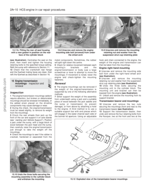 37
37 38
38 39
39 40
40 41
41 42
42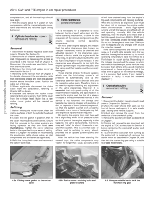 43
43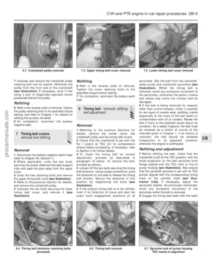 44
44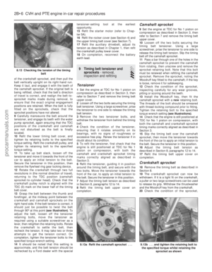 45
45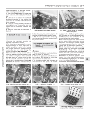 46
46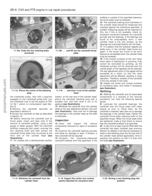 47
47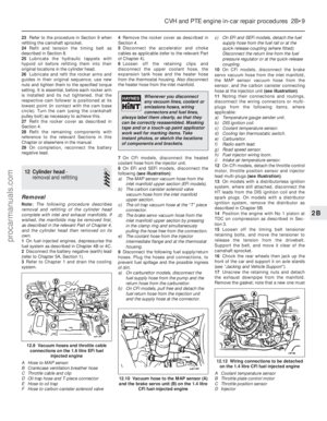 48
48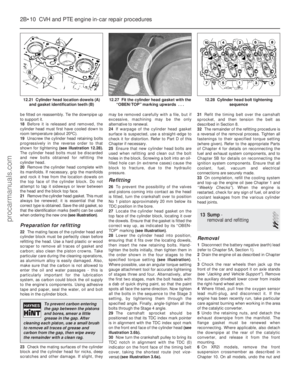 49
49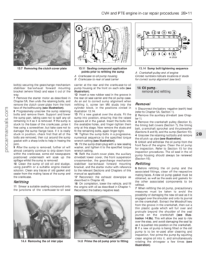 50
50 51
51 52
52 53
53 54
54 55
55 56
56 57
57 58
58 59
59 60
60 61
61 62
62 63
63 64
64 65
65 66
66 67
67 68
68 69
69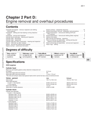 70
70 71
71 72
72 73
73 74
74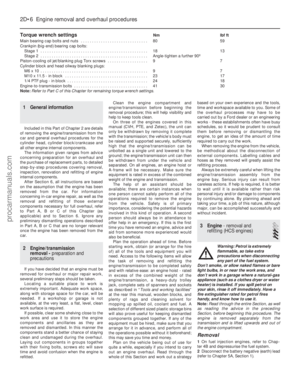 75
75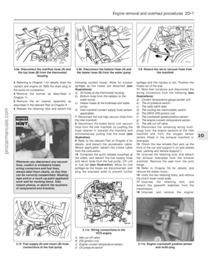 76
76 77
77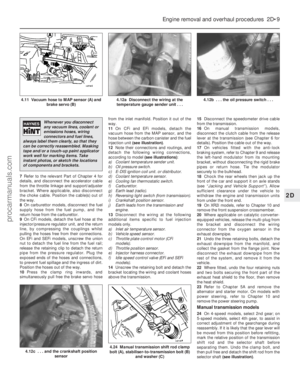 78
78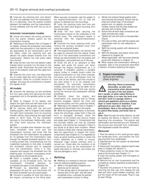 79
79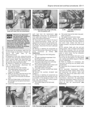 80
80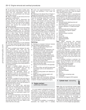 81
81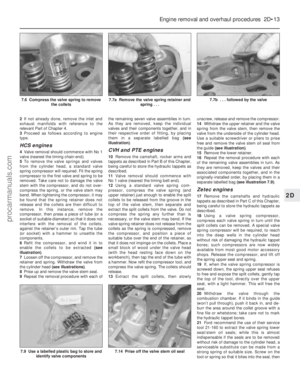 82
82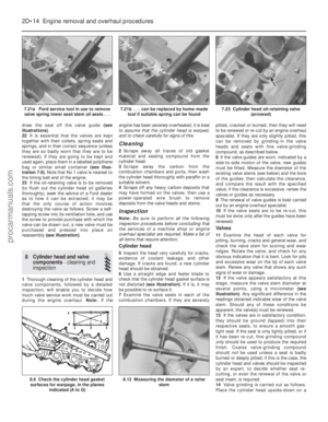 83
83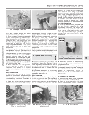 84
84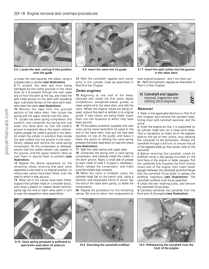 85
85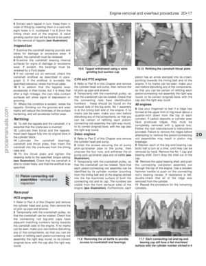 86
86 87
87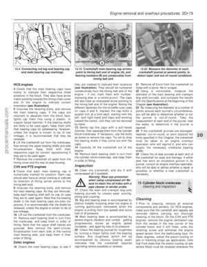 88
88 89
89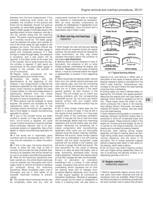 90
90 91
91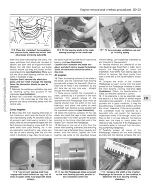 92
92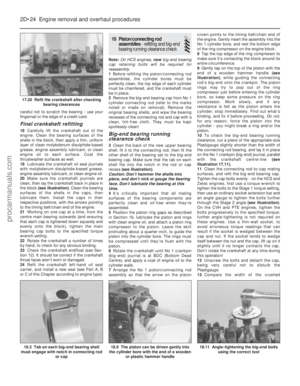 93
93 94
94 95
95 96
96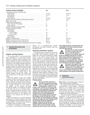 97
97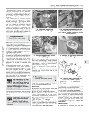 98
98 99
99 100
100 101
101 102
102 103
103 104
104 105
105 106
106 107
107 108
108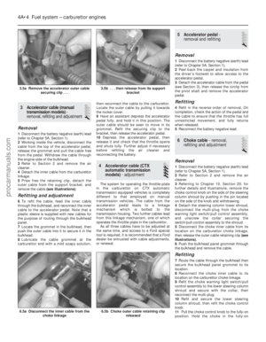 109
109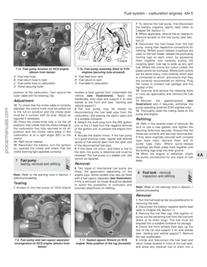 110
110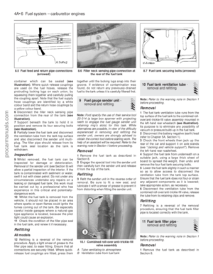 111
111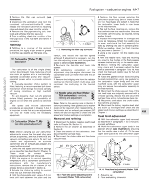 112
112 113
113 114
114 115
115 116
116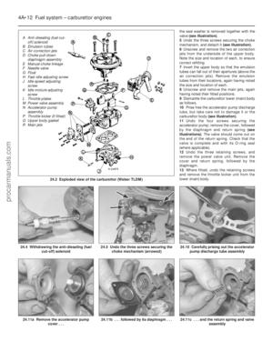 117
117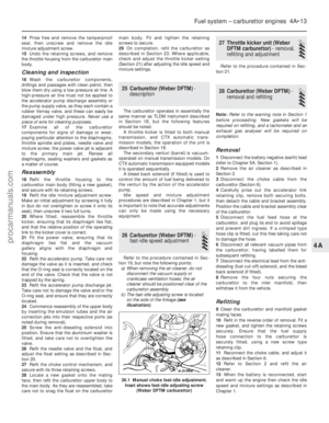 118
118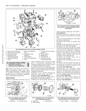 119
119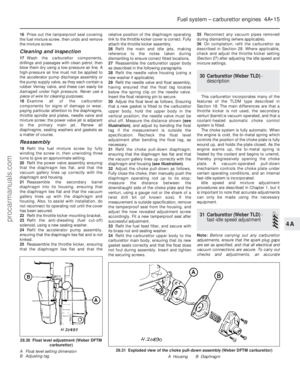 120
120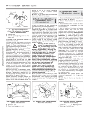 121
121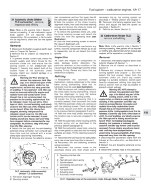 122
122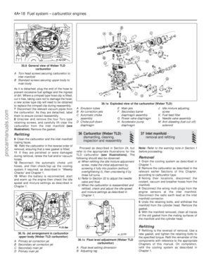 123
123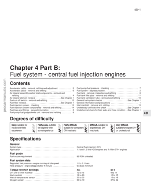 124
124 125
125 126
126 127
127 128
128 129
129 130
130 131
131 132
132 133
133 134
134 135
135 136
136 137
137 138
138 139
139 140
140 141
141 142
142 143
143 144
144 145
145 146
146 147
147 148
148 149
149 150
150 151
151 152
152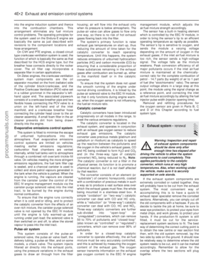 153
153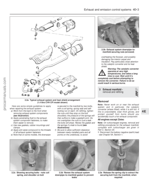 154
154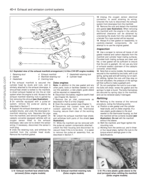 155
155 156
156 157
157 158
158 159
159 160
160 161
161 162
162 163
163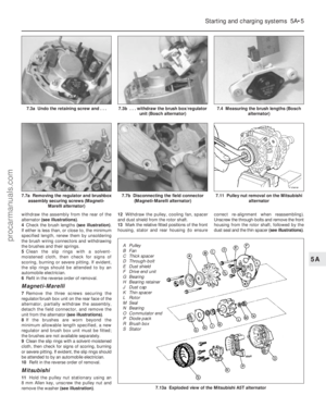 164
164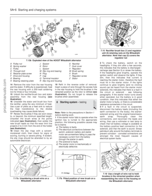 165
165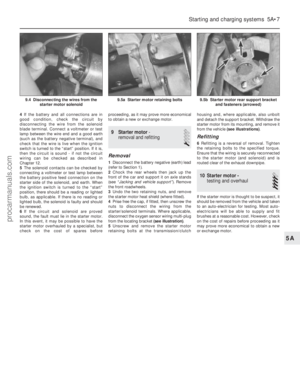 166
166 167
167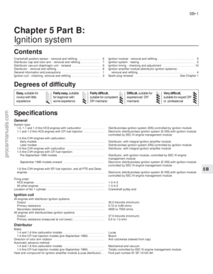 168
168 169
169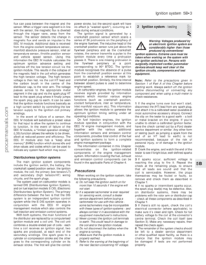 170
170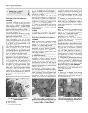 171
171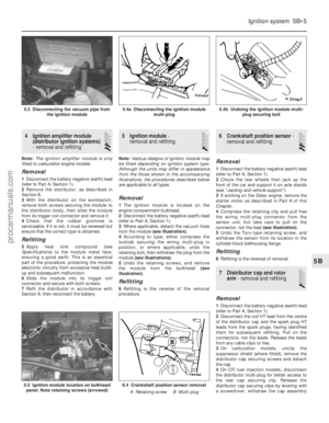 172
172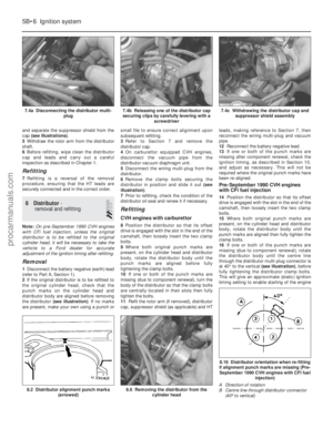 173
173 174
174 175
175 176
176 177
177 178
178 179
179 180
180 181
181 182
182 183
183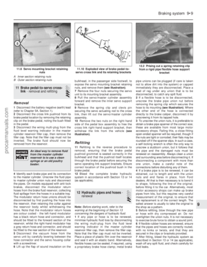 184
184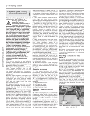 185
185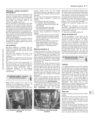 186
186 187
187 188
188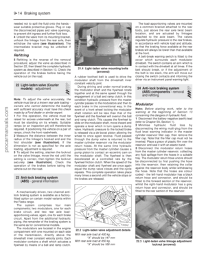 189
189 190
190 191
191 192
192 193
193 194
194 195
195 196
196 197
197 198
198 199
199 200
200 201
201 202
202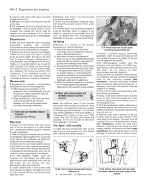 203
203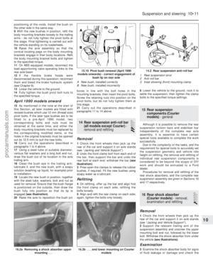 204
204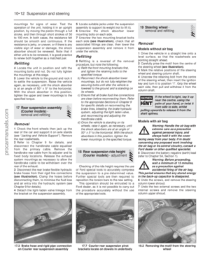 205
205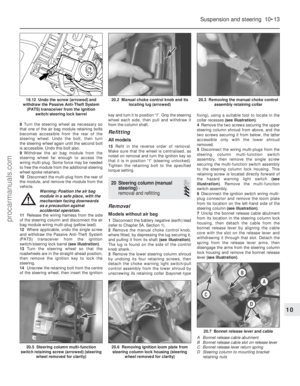 206
206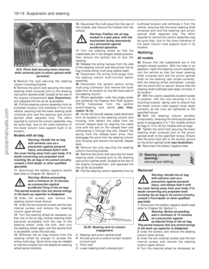 207
207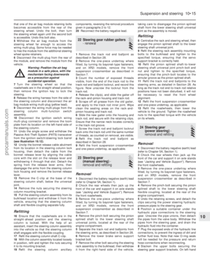 208
208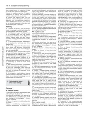 209
209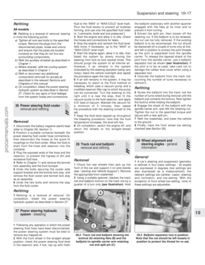 210
210 211
211 212
212 213
213 214
214 215
215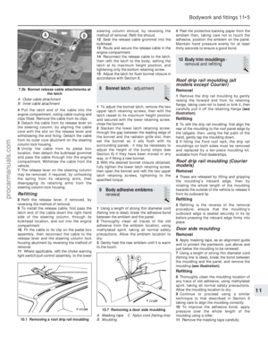 216
216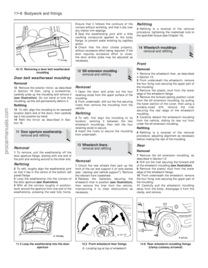 217
217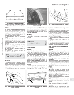 218
218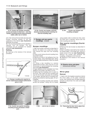 219
219 220
220 221
221 222
222 223
223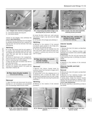 224
224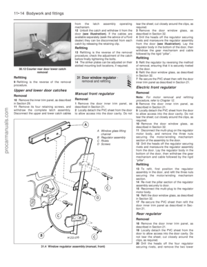 225
225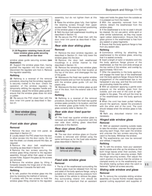 226
226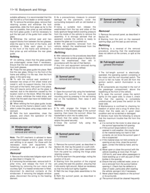 227
227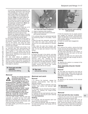 228
228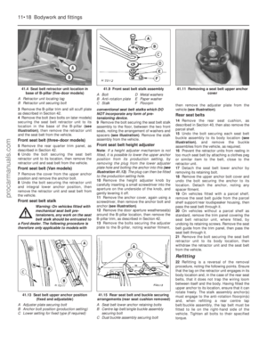 229
229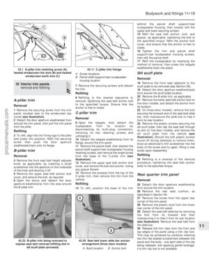 230
230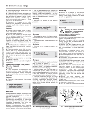 231
231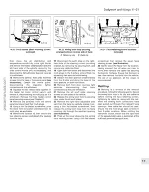 232
232 233
233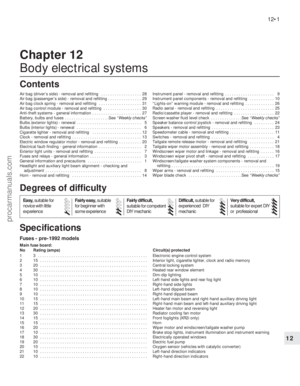 234
234 235
235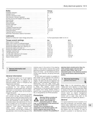 236
236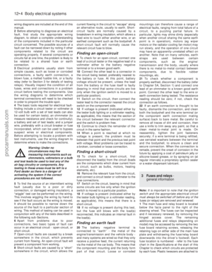 237
237 238
238 239
239 240
240 241
241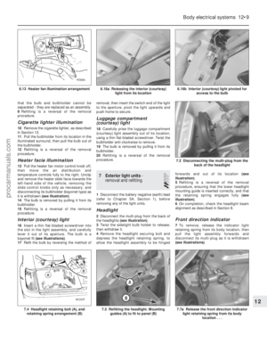 242
242 243
243 244
244 245
245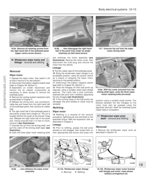 246
246 247
247 248
248 249
249 250
250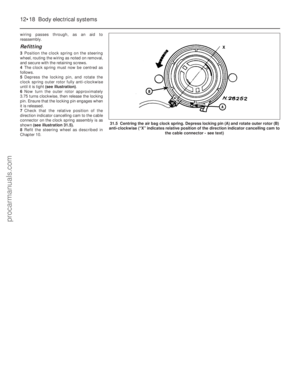 251
251 252
252 253
253 254
254 255
255 256
256 257
257 258
258 259
259 260
260 261
261 262
262 263
263 264
264 265
265 266
266 267
267 268
268 269
269 270
270 271
271 272
272 273
273 274
274 275
275 276
276 277
277 278
278 279
279 280
280 281
281 282
282 283
283 284
284 285
285 286
286 287
287 288
288 289
289 290
290 291
291 292
292 293
293 294
294 295
295