1989 FORD FIESTA brakes
[x] Cancel search: brakesPage 18 of 296
point at the engine to the end of the tailpipe.
Ideally, this should be done on a hoist, where
unrestricted access is available; if a hoist is
not available, raise and support the vehicle on
axle stands.
2Check the pipes and connections for
evidence of leaks, severe corrosion, or
damage. Make sure that all brackets and
rubber mountings are in good condition, and
tight; if any of the mountings are to be
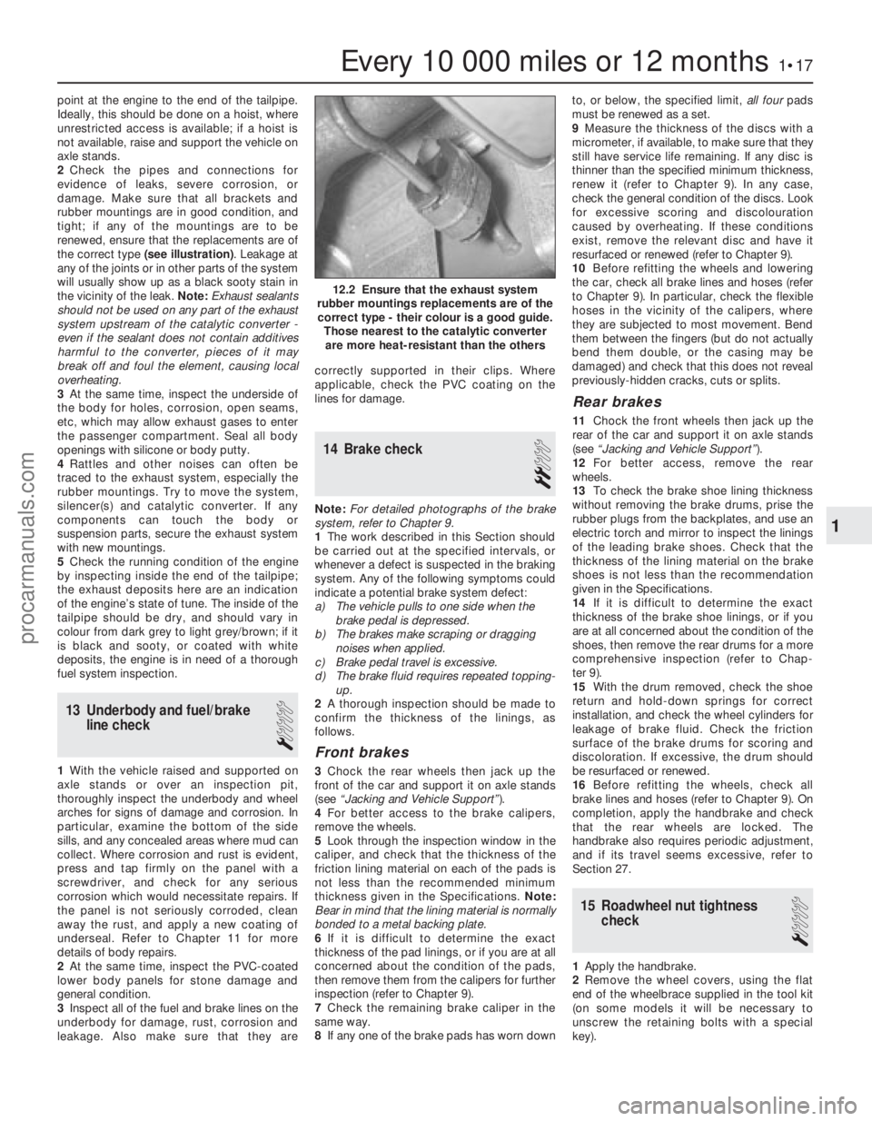
renewed, ensure that the replacements are of
the correct type (see illustration) . Leakage at
any of the joints or in other parts of the system
will usually show up as a black sooty stain in
the vicinity of the leak. Note: Exhaust sealants
should not be used on any part of the exhaust
system upstream of the catalytic converter -
even if the sealant does not contain additives
harmful to the converter, pieces of it may
break off and foul the element, causing local
overheating.
3 At the same time, inspect the underside of
the body for holes, corrosion, open seams,
etc, which may allow exhaust gases to enter
the passenger compartment. Seal all body
openings with silicone or body putty.
4 Rattles and other noises can often be
traced to the exhaust system, especially the
rubber mountings. Try to move the system,
silencer(s) and catalytic converter. If any
components can touch the body or
suspension parts, secure the exhaust system
with new mountings.
5 Check the running condition of the engine
by inspecting inside the end of the tailpipe;
the exhaust deposits here are an indication
of the engine’s state of tune. The inside of the
tailpipe should be dry, and should vary in
colour from dark grey to light grey/brown; if it
is black and sooty, or coated with white
deposits, the engine is in need of a thorough
fuel system inspection.
13 Underbody and fuel/brake line check
1
1With the vehicle raised and supported on
axle stands or over an inspection pit,
thoroughly inspect the underbody and wheel
arches for signs of damage and corrosion. In
particular, examine the bottom of the side
sills, and any concealed areas where mud can
collect. Where corrosion and rust is evident,
press and tap firmly on the panel with a
screwdriver, and check for any serious
corrosion which would necessitate repairs. If
the panel is not seriously corroded, clean
away the rust, and apply a new coating of
underseal. Refer to Chapter 11 for more
details of body repairs.
2 At the same time, inspect the PVC-coated
lower body panels for stone damage and
general condition.
3 Inspect all of the fuel and brake lines on the
underbody for damage, rust, corrosion and
leakage. Also make sure that they are correctly supported in their clips. Where
applicable, check the PVC coating on the
lines for damage.
14 Brake check
2
Note:
For detailed photographs of the brake
system, refer to Chapter 9.
1 The work described in this Section should
be carried out at the specified intervals, or
whenever a defect is suspected in the braking
system. Any of the following symptoms could
indicate a potential brake system defect:
a) The vehicle pulls to one side when the brake pedal is depressed.
b) The brakes make scraping or dragging
noises when applied.
c) Brake pedal travel is excessive.
d) The brake fluid requires repeated topping-
up.
2 A thorough inspection should be made to
confirm the thickness of the linings, as
follows.
Front brakes
3 Chock the rear wheels then jack up the
front of the car and support it on axle stands
(see “Jacking and Vehicle Support” ).
4 For better access to the brake calipers,
remove the wheels.
5 Look through the inspection window in the
caliper, and check that the thickness of the
friction lining material on each of the pads is
not less than the recommended minimum
thickness given in the Specifications. Note:
Bear in mind that the lining material is normally
bonded to a metal backing plate.
6 If it is difficult to determine the exact
thickness of the pad linings, or if you are at all
concerned about the condition of the pads,
then remove them from the calipers for further
inspection (refer to Chapter 9).
7 Check the remaining brake caliper in the
same way.
8 If any one of the brake pads has worn down to, or below, the specified limit,
all fourpads
must be renewed as a set.
9 Measure the thickness of the discs with a
micrometer, if available, to make sure that they
still have service life remaining. If any disc is
thinner than the specified minimum thickness,
renew it (refer to Chapter 9). In any case,
check the general condition of the discs. Look
for excessive scoring and discolouration
caused by overheating. If these conditions
exist, remove the relevant disc and have it
resurfaced or renewed (refer to Chapter 9).
10 Before refitting the wheels and lowering
the car, check all brake lines and hoses (refer
to Chapter 9). In particular, check the flexible
hoses in the vicinity of the calipers, where
they are subjected to most movement. Bend
them between the fingers (but do not actually
bend them double, or the casing may be
damaged) and check that this does not reveal
previously-hidden cracks, cuts or splits.
Rear brakes
11 Chock the front wheels then jack up the
rear of the car and support it on axle stands
(see “Jacking and Vehicle Support” ).
12 For better access, remove the rear
wheels.
13 To check the brake shoe lining thickness
without removing the brake drums, prise the
rubber plugs from the backplates, and use an
electric torch and mirror to inspect the linings
of the leading brake shoes. Check that the
thickness of the lining material on the brake
shoes is not less than the recommendation
given in the Specifications.
14 If it is difficult to determine the exact
thickness of the brake shoe linings, or if you
are at all concerned about the condition of the
shoes, then remove the rear drums for a more
comprehensive inspection (refer to Chap-
ter 9).
15 With the drum removed, check the shoe
return and hold-down springs for correct
installation, and check the wheel cylinders for
leakage of brake fluid. Check the friction
surface of the brake drums for scoring and
discoloration. If excessive, the drum should
be resurfaced or renewed.
16 Before refitting the wheels, check all
brake lines and hoses (refer to Chapter 9). On
completion, apply the handbrake and check
that the rear wheels are locked. The
handbrake also requires periodic adjustment,
and if its travel seems excessive, refer to
Section 27.
15 Roadwheel nut tightness check
1
1Apply the handbrake.
2 Remove the wheel covers, using the flat
end of the wheelbrace supplied in the tool kit
(on some models it will be necessary to
unscrew the retaining bolts with a special
key).
Every 10 000 miles or 12 months1•17
12.2 Ensure that the exhaust system
rubber mountings replacements are of the correct type - their colour is a good guide. Those nearest to the catalytic converterare more heat-resistant than the others
1
1595Ford Fiesta Remakeprocarmanuals.com
http://vnx.su
Page 176 of 296

9
1595Ford Fiesta Remake
Front brakes
Type . . . . . . . . . . . . . . . . . . . . . . . . . . . . . . . . . . . .\
. . . . . . . . . . . . . . . . Solid or ventilated disc, with single-piston sliding calipers
Disc diameter . . . . . . . . . . . . . . . . . . . . . . . . . . . . . . . . . . . .\
. . . . . . . . . 240.0 mm
Disc thickness:Solid disc . . . . . . . . . . . . . . . . . . . . . . . . . . . . . . . . . . . .\
. . . . . . . . . . 10.0 mm
Ventilated disc . . . . . . . . . . . . . . . . . . . . . . . . . . . . . . . . . . . .\
. . . . . . 20.0 mm
Minimum disc thickness:
Solid disc . . . . . . . . . . . . . . . . . . . . . . . . . . . . . . . . . . . .\
. . . . . . . . . . 8.0 mm
Ventilated disc . . . . . . . . . . . . . . . . . . . . . . . . . . . . . . . . . . . .\
. . . . . . 18.0 mm
Maximum disc run-out (disc fitted) . . . . . . . . . . . . . . . . . . . . . . . . . . . . . 0.1 mm
Minimum brake pad thickness . . . . . . . . . . . . . . . . . . . . . . . . . . . . . . . . 1.5 mm
Rear brakes
Type . . . . . . . . . . . . . . . . . . . . . . . . . . . . . . . . . . . .\
. . . . . . . . . . . . . . . . Drum with leading and trailing shoes and automatic adjusters
Nominal drum diameter: All except XR2i and ABS equipped models . . . . . . . . . . . . . . . . . . . . 180 mm
XR2i and ABS equipped models . . . . . . . . . . . . . . . . . . . . . . . . . . . . 203 mm
Maximum drum diameter . . . . . . . . . . . . . . . . . . . . . . . . . . . . . . . . . . . .\
1.0 mm above nominal diameter
Wheel cylinder bore diameter:
All except XR2i and ABS equipped models . . . . . . . . . . . . . . . . . . . . 17.5 mm
XR2i models with conventional braking system . . . . . . . . . . . . . . . . . 19.0 mm
All ABS equipped models . . . . . . . . . . . . . . . . . . . . . . . . . . . . . . . . . . 22.0 mm
Minimum brake shoe lining thickness . . . . . . . . . . . . . . . . . . . . . . . . . . 1.0 mm
Chapter 9
Braking system
ABS modulator drivebelt check . . . . . . . . . . . . . . . . . . . .See Chapter 1
Anti-lock braking system (ABS) - general information . . . . . . . . . . . 23
Anti-lock braking system (ABS) components - removal and refitting . . 24
Brake check . . . . . . . . . . . . . . . . . . . . . . . . . . . . . . . . . . .Se\
e Chapter 1
Brake fluid level check . . . . . . . . . . . . . . . . . . . . .See
“Weekly Checks”
Brake fluid renewal . . . . . . . . . . . . . . . . . . . . . . . . . . . . .See Chapter 1
Brake pedal - removal and refitting . . . . . . . . . . . . . . . . . . . . . . . . . . 10
Brake pedal-to-servo cross-link - removal and refitting . . . . . . . . . . 11
Brake pressure control valves - removal and refitting . . . . . . . . . . . 20
Front brake caliper - removal, overhaul and refitting . . . . . . . . . . . . 3
Front brake disc - inspection, removal and refitting . . . . . . . . . . . . . 4
Front brake pads - renewal . . . . . . . . . . . . . . . . . . . . . . . . . . . . . . . . 2
General information . . . . . . . . . . . . . . . . . . . . . . . . . . . . . . . . . . . .\
. . 1
Handbrake adjustment . . . . . . . . . . . . . . . . . . . . . . . . . .See Chapter 1
Handbrake lever - removal and refitting . . . . . . . . . . . . . . . . . . . . . . 17
Handbrake primary cable - removal and refitting . . . . . . . . . . . . . . . 18 Handbrake rear cable - removal and refitting . . . . . . . . . . . . . . . . . . 19
Hydraulic pipes and hoses - renewal . . . . . . . . . . . . . . . . . . . . . . . . 12
Hydraulic system - bleeding (anti-lock braking system) . . . . . . . . . . 14
Hydraulic system - bleeding (conventional braking system) . . . . . . . 13
Light-laden valve (Courier models) - adjustment . . . . . . . . . . . . . . . 22
Light-laden valve (Courier models) - removal and refitting . . . . . . . . 21
Load-apportioning valve (ABS models) - adjustment . . . . . . . . . . . . 25
Load-apportioning valve (ABS models) - removal and refitting . . . . 26
Master cylinder - removal, overhaul and refitting . . . . . . . . . . . . . . . 9
Rear brake backplate - removal and refitting . . . . . . . . . . . . . . . . . . 8
Rear brake drum - removal, inspection and refitting . . . . . . . . . . \
. . . 5
Rear brake shoes - renewal . . . . . . . . . . . . . . . . . . . . . . . . . . . . . . . 6
Rear wheel cylinder - removal, overhaul and refitting . . . . . . . . . . . . 7
Vacuum servo unit - testing, removal and refitting . . . . . . . . . . . . . . 15
Vacuum servo unit vacuum hose and non-return valve - removal,
testing and refitting . . . . . . . . . . . . . . . . . . . . . . . . . . . . . . . . . . . .\
16
9•1
Specifications Contents
Easy, suitable for
novice with little
experience Fairly easy,
suitable
for beginner with
some experience Fairly difficult,
suitable for competent
DIY mechanic
Difficult,
suitable for
experienced DIY
mechanic Very difficult,
suitable for expert DIY
or professional
Degrees of difficulty
54321
procarmanuals.com
http://vnx.su
Page 177 of 296
1 General information
The braking system is of the diagonally
split, dual-circuit hydraulic type, with servo
assistance to the front disc brakes and rear
drum brakes. The dual-circuit hydraulic
system is a safety feature - in the event of a
malfunction somewhere in one of the
hydraulic circuits, the other circuit continues
to operate, providing at least some braking
effort. Under normal circumstances, both
brake circuits operate in unison, to provide
efficient braking.
The master cylinder (and the vacuum servo
unit to which it is bolted) is located on the left-
hand side of the bulkhead in the engine
compartment. On all right-hand drive variants,
they are jointly operated via a transverse
cross-link from the brake pedal.
Brake pressure control valves are fitted in-
line to each rear brake circuit, their function
being to regulate the braking force available at
each rear wheel, reducing the possibility of
the rear wheels locking up under heavy
braking. Courier models also have a “light-
laden” valve incorporated into the rear braking
circuits for the same reason. The front brake discs are of the ventilated
type on XR2i and ABS-equipped models, with
solid discs fitted on all other models. The front
brake calipers are of single sliding piston type
mounted on the front spindle carriers each
side. Each rear brake shoe assembly is operated
by a twin-piston wheel cylinder. The leading
brake shoe in each brake unit has a thicker
lining than the trailing shoe, so that they wear
proportionally. To take up the brake
adjustment as the linings wear, each rear
brake assembly incorporates an automatic
adjuster mechanism. The cable-operated handbrake acts on
both rear brakes, to provide an independent
means of brake operation. An anti-lock braking system (ABS) is
available on some models, and has many of
the components in common with the conventional braking system. Further details
on ABS can be found later in this Chapter.
Note:
When servicing any part of the system,
work carefully and methodically; also observe
scrupulous cleanliness when overhauling any
part of the hydraulic system. Always renew
components (in axle sets, where applicable) if
in doubt about their condition, and use only
genuine Ford replacement parts, or at least
those of known good quality. Note the
warnings given in “Safety first” and at relevant
points in this Chapter concerning the dangers
of asbestos dust and hydraulic fluid.
2 Front brake pads - renewal
2
Warning: Disc brake pads MUST
be renewed on both front
wheels at the same time -
NEVER renew the pads on only
one wheel, as uneven braking may result.
The front brake calipers will be of Bendix
or Teves manufacture, and if they or their
component parts require renewal, ensure
that the correct type is fitted. Dust created
by wear of the pads may contain asbestos,
which is a health hazard. Never blow it out
with compressed air, and do not inhale any
of it. DO NOT use petroleum-based
solvents to clean brake parts - use brake
cleaner or methylated spirit only. DO NOT allow any brake fluid, oil or grease to
contact the brake pads or disc. Also refer
to the warning in Section 13 concerning
the dangers of hydraulic fluid.
1
Chock the rear wheels then jack up the
front of the car and support it on axle stands
(see “Jacking and Vehicle Support” ). Remove
the front roadwheels.
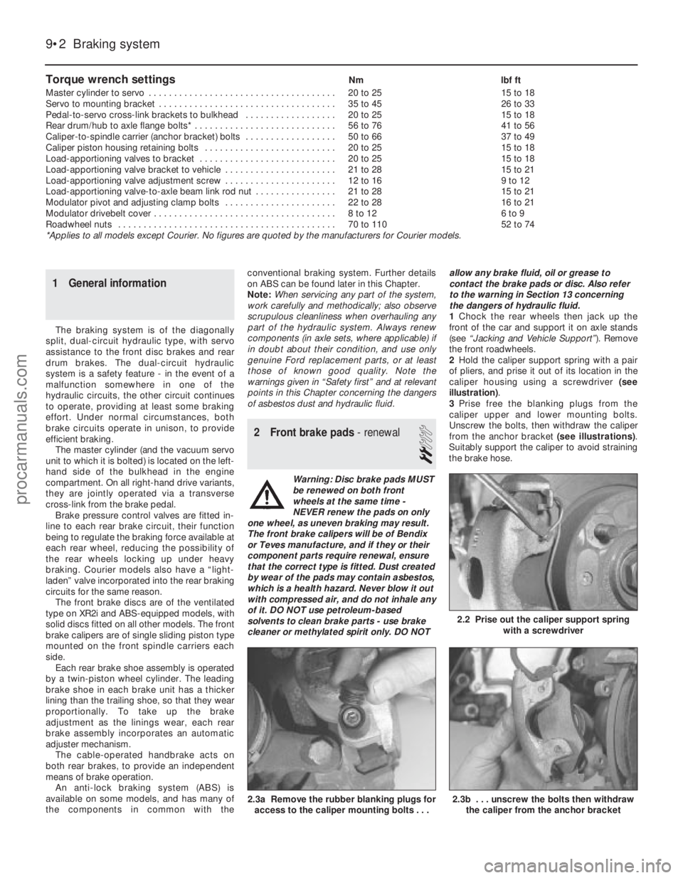
2 Hold the caliper support spring with a pair
of pliers, and prise it out of its location in the
caliper housing using a screwdriver (see
illustration) .
3 Prise free the blanking plugs from the
caliper upper and lower mounting bolts.
Unscrew the bolts, then withdraw the caliper
from the anchor bracket (see illustrations).
Suitably support the caliper to avoid straining
the brake hose.
Torque wrench settingsNm lbf ft
Master cylinder to servo . . . . . . . . . . . . . . . . . . . . . . . . . . . . . . . . . . . .\
. 20 to 25 15 to 18
Servo to mounting bracket . . . . . . . . . . . . . . . . . . . . . . . . . . . . . . . . . . . 35 to 45 26 to 33
Pedal-to-servo cross-link brackets to bulkhead . . . . . . . . . . . . . . . . . . 20 to 25 15 to 18
Rear drum/hub to axle flange bolts* . . . . . . . . . . . . . . . . . . . . . . . . . . . . 56 to 76 41 to 56
Caliper-to-spindle carrier (anchor bracket) bolts . . . . . . . . . . . . . . . . . . 50 to 66 37 to 49
Caliper piston housing retaining bolts . . . . . . . . . . . . . . . . . . . . . . . . . . 20 to 25 15 to 18
Load-apportioning valves to bracket . . . . . . . . . . . . . . . . . . . . . . . . . . . 20 to 25 15 to 18
Load-apportioning valve bracket to vehicle . . . . . . . . . . . . . . . . . . . . . . 21 to 28 15 to 21
Load-apportioning valve adjustment screw . . . . . . . . . . . . . . . . . . . . . . 12 to 16 9 to 12
Load-apportioning valve-to-axle beam link rod nut . . . . . . . . . . . . . . . . 21 to 28 15 to 21
Modulator pivot and adjusting clamp bolts . . . . . . . . . . . . . . . . . . . . . . 22 to 28 16 to 21
Modulator drivebelt cover . . . . . . . . . . . . . . . . . . . . . . . . . . . . . . . . . . . .\
8 to 12 6 to 9
Roadwheel nuts . . . . . . . . . . . . . . . . . . . . . . . . . . . . . . . . . . . .\
. . . . . . . 70 to 110 52 to 74
*Applies to all models except Courier. No figures are quoted by the manu\
facturers for Courier models.
9•2 Braking system
2.3b . . . unscrew the bolts then withdraw the caliper from the anchor bracket2.3a Remove the rubber blanking plugs foraccess to the caliper mounting bolts . . .
2.2 Prise out the caliper support spring with a screwdriver
1595Ford Fiesta Remakeprocarmanuals.com
http://vnx.su
Page 180 of 296
wheel cylinder and backplate. Take great care
not to inhale the dust, as it may contain
asbestos.
4 If required, remove the hub from the drum
as described in Chapter 10.
Inspection
Note: If a brake drum requires renewal, BOTH
rear drums should be renewed at the same
time to ensure even and consistent
braking. New brake shoes should also be
fitted.
5 Clean the inside surfaces of the brake drum
and hub, then examine the internal surface of
the brake drum for signs of scoring or cracks.
If any deterioration of the friction surface is
evident, renewal of the drum is necessary. To
detach the hub from the drum, refer to
Chapter 10.
Refitting
6 Check that the automatic brake adjuster is
fully retracted, then refit the drum/hub to the
axle. Tighten the retaining bolts to the
specified torque.
7 With the brake drum refitted, refit the
roadwheel. Fully depress the brake pedal
several times, to actuate the rear brake
adjuster and take up the adjustment. Check
that the rear wheels spin freely when the
brakes are released, then apply the
handbrake, lower the vehicle and tighten the
wheel nuts to the specified torque.
6 Rear brake shoes - renewal
2
Warning: Drum brake shoes
MUST be renewed on both rear
wheels at the same time -
NEVER renew the shoes on only
one wheel, as uneven braking may result.
Also, the dust created by wear of the
shoes may contain asbestos, which is a
health hazard. Never blow it out with
compressed air, and don’t inhale any of it.
An approved filtering mask should be worn
when working on the brakes. DO NOT use
petroleum-based solvents to clean brake
parts - use brake cleaner or methylated
spirit only.
1 Remove the rear brake drum with reference
to Section 5.
2 Note the fitted positions of the springs and
the adjuster strut.
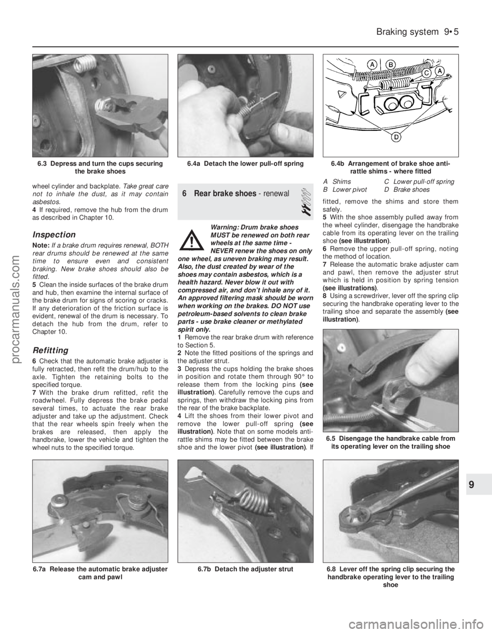
3 Depress the cups holding the brake shoes
in position and rotate them through 90° to
release them from the locking pins (see
illustration) . Carefully remove the cups and
springs, then withdraw the locking pins from
the rear of the brake backplate.
4 Lift the shoes from their lower pivot and
remove the lower pull-off spring (see
illustration) . Note that on some models anti-
rattle shims may be fitted between the brake
shoe and the lower pivot (see illustration). Iffitted, remove the shims and store them
safely.
5
With the shoe assembly pulled away from
the wheel cylinder, disengage the handbrake
cable from its operating lever on the trailing
shoe (see illustration) .
6 Remove the upper pull-off spring, noting
the method of location.
7 Release the automatic brake adjuster cam
and pawl, then remove the adjuster strut
which is held in position by spring tension
(see illustrations) .
8 Using a screwdriver, lever off the spring clip
securing the handbrake operating lever to the
trailing shoe and separate the assembly (see
illustration) .
Braking system 9•5
6.4b Arrangement of brake shoe anti-
rattle shims - where fitted
A Shims C Lower pull-off spring
B Lower pivot D Brake shoes
6.5 Disengage the handbrake cable from its operating lever on the trailing shoe
6.4a Detach the lower pull-off spring6.3 Depress and turn the cups securing the brake shoes
6.8 Lever off the spring clip securing thehandbrake operating lever to the trailing
shoe6.7b Detach the adjuster strut6.7a Release the automatic brake adjustercam and pawl
9
1595Ford Fiesta Remakeprocarmanuals.com
http://vnx.su
Page 182 of 296
8 Rear brake backplate-
removal and refitting
3
Removal
1 Remove the brake drum/hub assembly as
described in Section 5.
2 Remove the rear brake shoes as described
in Section 6.
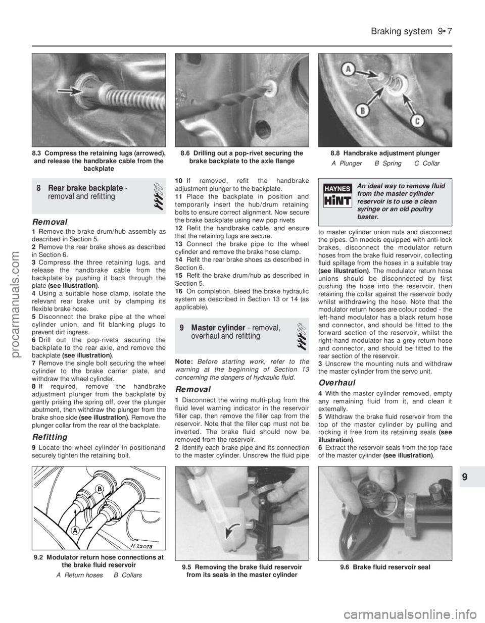
3 Compress the three retaining lugs, and
release the handbrake cable from the
backplate by pushing it back through the
plate (see illustration) .
4 Using a suitable hose clamp, isolate the
relevant rear brake unit by clamping its
flexible brake hose.
5 Disconnect the brake pipe at the wheel
cylinder union, and fit blanking plugs to
prevent dirt ingress.
6 Drill out the pop-rivets securing the
backplate to the rear axle, and remove the
backplate (see illustration) .
7 Remove the single bolt securing the wheel
cylinder to the brake carrier plate, and
withdraw the wheel cylinder.
8 If required, remove the handbrake
adjustment plunger from the backplate by
gently prising the spring off, over the plunger
abutment, then withdraw the plunger from the
brake shoe side (see illustration) . Remove the
plunger collar from the rear of the backplate.
Refitting
9 Locate the wheel cylinder in positionand
securely tighten the retaining bolt. 10
If removed, refit the handbrake
adjustment plunger to the backplate.
11 Place the backplate in position and
temporarily insert the hub/drum retaining
bolts to ensure correct alignment. Now secure
the brake backplate using new pop rivets
12 Refit the handbrake cable, and ensure
that the retaining lugs are secure.
13 Connect the brake pipe to the wheel
cylinder and remove the brake hose clamp.
14 Refit the rear brake shoes as described in
Section 6.
15 Refit the brake drum/hub as described in
Section 5.
16 On completion, bleed the brake hydraulic
system as described in Section 13 or 14 (as
applicable).
9 Master cylinder - removal,
overhaul and refitting
3
Note: Before starting work, refer to the
warning at the beginning of Section 13
concerning the dangers of hydraulic fluid.
Removal
1 Disconnect the wiring multi-plug from the
fluid level warning indicator in the reservoir
filler cap, then remove the filler cap from the
reservoir. Note that the filler cap must not be
inverted. The brake fluid should now be
removed from the reservoir.
2 Identify each brake pipe and its connection
to the master cylinder. Unscrew the fluid pipe to master cylinder union nuts and disconnect
the pipes. On models equipped with anti-lock
brakes, disconnect the modulator return
hoses from the brake fluid reservoir, collecting
fluid spillage from the hoses in a suitable tray
(see illustration)
. The modulator return hose
unions should be disconnected by first
pushing the hose into the reservoir, then
retaining the collar against the reservoir body
whilst withdrawing the hose. Note that the
modulator return hoses are colour coded - the
left-hand modulator has a black return hose
and connector, and should be fitted to the
forward section of the reservoir, whilst the
right-hand modulator has a grey return hose
and connector, and should be fitted to the
rear section of the reservoir.
3 Unscrew the mounting nuts and withdraw
the master cylinder from the servo unit.
Overhaul
4 With the master cylinder removed, empty
any remaining fluid from it, and clean it
externally.
5 Withdraw the brake fluid reservoir from the
top of the master cylinder by pulling and
rocking it free from its retaining seals (see
illustration) .
6 Extract the reservoir seals from the top face
of the master cylinder (see illustration).
Braking system 9•7
8.8 Handbrake adjustment plunger
A Plunger B Spring C Collar8.6 Drilling out a pop-rivet securing the brake backplate to the axle flange8.3 Compress the retaining lugs (arrowed),and release the handbrake cable from the backplate
9.5 Removing the brake fluid reservoirfrom its seals in the master cylinder
9.2 Modulator return hose connections at the brake fluid reservoir
A Return hoses B Collars
9
1595Ford Fiesta Remake 9.6 Brake fluid reservoir seal
An ideal way to remove fluid
from the master cylinder
reservoir is to use a clean
syringe or an old poultry
baster.
procarmanuals.com
http://vnx.su
Page 183 of 296
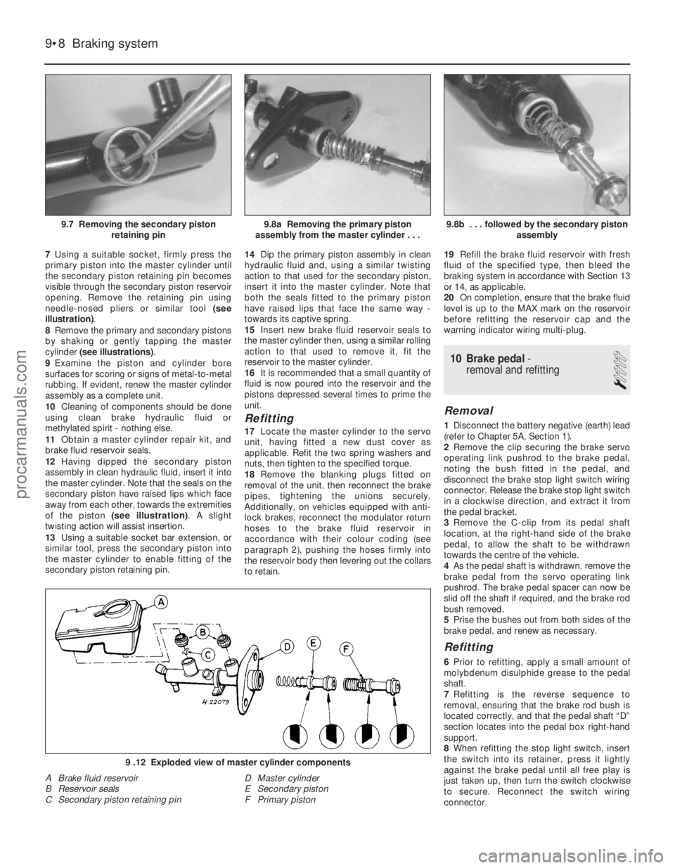
7Using a suitable socket, firmly press the
primary piston into the master cylinder until
the secondary piston retaining pin becomes
visible through the secondary piston reservoir
opening. Remove the retaining pin using
needle-nosed pliers or similar tool (see
illustration) .
8 Remove the primary and secondary pistons
by shaking or gently tapping the master
cylinder (see illustrations) .
9 Examine the piston and cylinder bore
surfaces for scoring or signs of metal-to-metal
rubbing. If evident, renew the master cylinder
assembly as a complete unit.
10 Cleaning of components should be done
using clean brake hydraulic fluid or
methylated spirit - nothing else.
11 Obtain a master cylinder repair kit, and
brake fluid reservoir seals.
12 Having dipped the secondary piston
assembly in clean hydraulic fluid, insert it into
the master cylinder. Note that the seals on the
secondary piston have raised lips which face
away from each other, towards the extremities
of the piston (see illustration) . A slight
twisting action will assist insertion.
13 Using a suitable socket bar extension, or
similar tool, press the secondary piston into
the master cylinder to enable fitting of the
secondary piston retaining pin. 14
Dip the primary piston assembly in clean
hydraulic fluid and, using a similar twisting
action to that used for the secondary piston,
insert it into the master cylinder. Note that
both the seals fitted to the primary piston
have raised lips that face the same way -
towards its captive spring.
15 Insert new brake fluid reservoir seals to
the master cylinder then, using a similar rolling
action to that used to remove it, fit the
reservoir to the master cylinder.
16 It is recommended that a small quantity of
fluid is now poured into the reservoir and the
pistons depressed several times to prime the
unit.
Refitting
17 Locate the master cylinder to the servo
unit, having fitted a new dust cover as
applicable. Refit the two spring washers and
nuts, then tighten to the specified torque.
18 Remove the blanking plugs fitted on
removal of the unit, then reconnect the brake
pipes, tightening the unions securely.
Additionally, on vehicles equipped with anti-
lock brakes, reconnect the modulator return
hoses to the brake fluid reservoir in
accordance with their colour coding (see
paragraph 2), pushing the hoses firmly into
the reservoir body then levering out the collars
to retain. 19
Refill the brake fluid reservoir with fresh
fluid of the specified type, then bleed the
braking system in accordance with Section 13
or 14, as applicable.
20 On completion, ensure that the brake fluid
level is up to the MAX mark on the reservoir
before refitting the reservoir cap and the
warning indicator wiring multi-plug.
10 Brake pedal -
removal and refitting
1
Removal
1 Disconnect the battery negative (earth) lead
(refer to Chapter 5A, Section 1).
2 Remove the clip securing the brake servo
operating link pushrod to the brake pedal,
noting the bush fitted in the pedal, and
disconnect the brake stop light switch wiring
connector. Release the brake stop light switch
in a clockwise direction, and extract it from
the pedal bracket.
3 Remove the C-clip from its pedal shaft
location, at the right-hand side of the brake
pedal, to allow the shaft to be withdrawn
towards the centre of the vehicle.
4 As the pedal shaft is withdrawn, remove the
brake pedal from the servo operating link
pushrod. The brake pedal spacer can now be
slid off the shaft if required, and the brake rod
bush removed.
5 Prise the bushes out from both sides of the
brake pedal, and renew as necessary.
Refitting
6 Prior to refitting, apply a small amount of
molybdenum disulphide grease to the pedal
shaft.
7 Refitting is the reverse sequence to
removal, ensuring that the brake rod bush is
located correctly, and that the pedal shaft “D”
section locates into the pedal box right-hand
support.
8 When refitting the stop light switch, insert
the switch into its retainer, press it lightly
against the brake pedal until all free play is
just taken up, then turn the switch clockwise
to secure. Reconnect the switch wiring
connector.
9•8 Braking system
9 .12 Exploded view of master cylinder components
A Brake fluid reservoir
B Reservoir seals
C Secondary piston retaining pin D Master cylinder
E Secondary piston
F Primary piston
9.8b . . . followed by the secondary piston
assembly9.8a Removing the primary piston
assembly from the master cylinder . . .9.7 Removing the secondary piston retaining pin
1595Ford Fiesta Remakeprocarmanuals.com
http://vnx.su
Page 184 of 296
11 Brake pedal-to-servo cross-link - removal and refitting
3
Removal
1Disconnect the battery negative (earth) lead
(refer to Chapter 5A, Section 1).
2 Disconnect the cross link pushrod from its
brake pedal location by removing the retaining
clip on the brake pedal, noting the bush fitted
in the pedal.
3 Disconnect the wiring multi-plug from the
fluid level warning indicator in the master
cylinder reservoir filler cap, then remove the
filler cap. Note that the filler cap must not be
inverted. The brake fluid should now be
removed from the reservoir.
4 Identify each brake pipe and its connection
to the master cylinder. Unscrew the fluid pipe
to master cylinder union nuts and disconnect
the pipes. On models equipped with anti-lock
brakes, disconnect the modulator return
hoses from the brake fluid reservoir, collecting
fluid spillage from the hoses in a suitable tray.
The modulator return hose unions should be
disconnected by first pushing the hose into
the reservoir, then retaining the collar against
the reservoir body whilst withdrawing the
hose. Note that the modulator return hoses
are colour coded - the left-hand modulator
has a black return hose and connector, and
should be fitted to the forward section of the
reservoir, whilst the right-hand modulator has
a grey return hose and connector, and should
be fitted to the rear section of the reservoir.
5 Disconnect the vacuum hose from the
servo unit by carefully levering between the
hose connector and the servo housing collar
with a screwdriver.
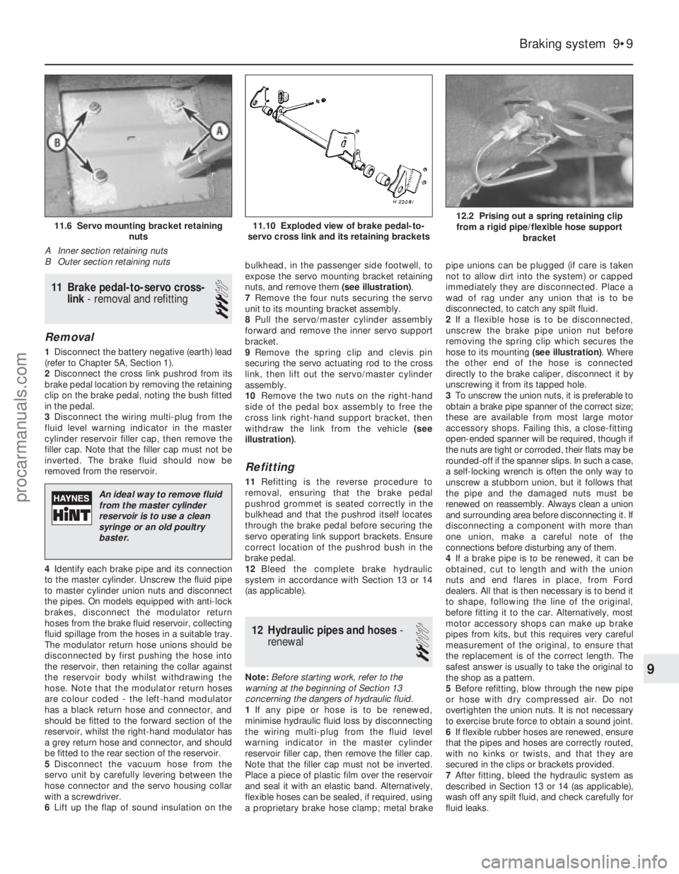
6 Lift up the flap of sound insulation on the bulkhead, in the passenger side footwell, to
expose the servo mounting bracket retaining
nuts, and remove them
(see illustration).
7 Remove the four nuts securing the servo
unit to its mounting bracket assembly.
8 Pull the servo/master cylinder assembly
forward and remove the inner servo support
bracket.
9 Remove the spring clip and clevis pin
securing the servo actuating rod to the cross
link, then lift out the servo/master cylinder
assembly.
10 Remove the two nuts on the right-hand
side of the pedal box assembly to free the
cross link right-hand support bracket, then
withdraw the link from the vehicle (see
illustration) .
Refitting
11Refitting is the reverse procedure to
removal, ensuring that the brake pedal
pushrod grommet is seated correctly in the
bulkhead and that the pushrod itself locates
through the brake pedal before securing the
servo operating link support brackets. Ensure
correct location of the pushrod bush in the
brake pedal.
12 Bleed the complete brake hydraulic
system in accordance with Section 13 or 14
(as applicable).
12 Hydraulic pipes and hoses -
renewal
2
Note: Before starting work, refer to the
warning at the beginning of Section 13
concerning the dangers of hydraulic fluid.
1 If any pipe or hose is to be renewed,
minimise hydraulic fluid loss by disconnecting
the wiring multi-plug from the fluid level
warning indicator in the master cylinder
reservoir filler cap, then remove the filler cap.
Note that the filler cap must not be inverted.
Place a piece of plastic film over the reservoir
and seal it with an elastic band. Alternatively,
flexible hoses can be sealed, if required, using
a proprietary brake hose clamp; metal brake pipe unions can be plugged (if care is taken
not to allow dirt into the system) or capped
immediately they are disconnected. Place a
wad of rag under any union that is to be
disconnected, to catch any spilt fluid.
2
If a flexible hose is to be disconnected,
unscrew the brake pipe union nut before
removing the spring clip which secures the
hose to its mounting (see illustration). Where
the other end of the hose is connected
directly to the brake caliper, disconnect it by
unscrewing it from its tapped hole.
3 To unscrew the union nuts, it is preferable to
obtain a brake pipe spanner of the correct size;
these are available from most large motor
accessory shops. Failing this, a close-fitting
open-ended spanner will be required, though if
the nuts are tight or corroded, their flats may be
rounded-off if the spanner slips. In such a case,
a self-locking wrench is often the only way to
unscrew a stubborn union, but it follows that
the pipe and the damaged nuts must be
renewed on reassembly. Always clean a union
and surrounding area before disconnecting it. If
disconnecting a component with more than
one union, make a careful note of the
connections before disturbing any of them.
4 If a brake pipe is to be renewed, it can be
obtained, cut to length and with the union
nuts and end flares in place, from Ford
dealers. All that is then necessary is to bend it
to shape, following the line of the original,
before fitting it to the car. Alternatively, most
motor accessory shops can make up brake
pipes from kits, but this requires very careful
measurement of the original, to ensure that
the replacement is of the correct length. The
safest answer is usually to take the original to
the shop as a pattern.
5 Before refitting, blow through the new pipe
or hose with dry compressed air. Do not
overtighten the union nuts. It is not necessary
to exercise brute force to obtain a sound joint.
6 If flexible rubber hoses are renewed, ensure
that the pipes and hoses are correctly routed,
with no kinks or twists, and that they are
secured in the clips or brackets provided.
7 After fitting, bleed the hydraulic system as
described in Section 13 or 14 (as applicable),
wash off any spilt fluid, and check carefully for
fluid leaks.
Braking system 9•9
12.2 Prising out a spring retaining clip from a rigid pipe/flexible hose support bracket11.10 Exploded view of brake pedal-to-
servo cross link and its retaining brackets11.6 Servo mounting bracket retaining nuts
A Inner section retaining nuts
B Outer section retaining nuts
9
1595Ford Fiesta Remake
An ideal way to remove fluid from the master cylinder
reservoir is to use a clean
syringe or an old poultry
baster.
procarmanuals.com
http://vnx.su
Page 186 of 296
Bleeding - using a pressure-
bleeding kit
24These kits are usually operated by the
reservoir of pressurised air contained in the
spare tyre. However, note that it will probably
be necessary to reduce the pressure to a
lower level than normal; refer to the
instructions supplied with the kit.
25 By connecting a pressurised, fluid-filled
container to the master cylinder reservoir,
bleeding can be carried out simply by opening
each screw in turn (in the specified sequence),
and allowing the fluid to flow out until no more
air bubbles can be seen in the expelled fluid.
26 This method has the advantage that the
large reservoir of fluid provides an additional
safeguard against air being drawn into the
system during bleeding.
27 Pressure-bleeding is particularly effective
when bleeding “difficult” systems, or when
bleeding the complete system at the time of
routine fluid renewal.
All methods
28 When bleeding is complete, and firm
pedal feel is restored, wash off any spilt fluid,
tighten the bleed screws securely, and refit
their dust caps.
29 Check the hydraulic fluid level in the
master cylinder reservoir, and top-up if
necessary.
30 Discard any hydraulic fluid that has been
bled from the system; it will not be fit for re-
use.
31 Check the feel of the brake pedal. If it
feels at all spongy, air must still be present in
the system, and further bleeding is required.
Failure to bleed satisfactorily after a
reasonable repetition of the bleeding
procedure may be due to worn master
cylinder seals.
14 Hydraulic system - bleeding
(anti-lock braking system)
3
Note: Before starting work, refer to the
warning at the beginning of Section 13
concerning the dangers of hydraulic fluid.
1 On vehicles equipped with the anti-lock braking system there are two bleed
procedures possible, depending on which
part of the brake hydraulic system has been
disturbed.
2
If any one of the following conditions are
present, bleed procedure A should be
adopted: a) A modulator has been removed.
b) A modulator return hose (between
modulator and brake fluid reservoir) has
been drained.
c) The rigid brake pipes have been disconnected from a modulator.
3 If any one of the following conditions are
present, bleed procedure B should be
adopted: a) Any condition where the master cylinder
has been removed or drained, providing
that the modulator return hoses have not
lost their head of fluid.
b) Removal or disconnection of any of the
basic braking system components ie,
brake caliper, flexible hose or rigid pipe,
wheel cylinder, or load-apportioning
valve.
Bleed procedure A
4Raise the vehicle on ramps, or drive it over
an inspection pit, so that working clearance
may be obtained with the full weight of the
vehicle on its roadwheels. Remove the one-
piece undertray, as applicable, by turning its
bayonet-type fasteners and, on XR2i models,
remove the front suspension crossmember
(see Chapter 10).
5 Disconnect the wiring multi-plug from the
fluid level warning indicator in the master
cylinder reservoir filler cap, then remove the
filler cap. Note that the filler cap must not be
inverted. Top-up the brake fluid reservoir to
the MAX mark using fresh fluid of the
specified type (see “Weekly Checks”), and
keep it topped up throughout the bleeding
procedure.
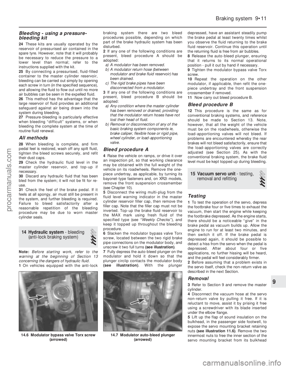
6 Slacken the modulator bypass valve Torx
screw, located between the two rigid brake
pipe connections on the modulator body, and
unscrew it two full turns (see illustration).
7 Fully depress the auto-bleed plunger on the
modulator and hold it down so that the
plunger circlip contacts the modulator body
(see illustration) . With the plunger depressed, have an assistant steadily pump
the brake pedal at least twenty times whilst
you observe the fluid returning to the brake
fluid reservoir. Continue this operation until
the returning fluid is free from air bubbles.
8
Release the auto-bleed plunger, ensuring
that it returns to its normal operational
position - pull it out by hand if necessary.
9 Tighten the modulator bypass valve Torx
screw.
10 Repeat the operation on the other
modulator, if applicable, then refit the one-
piece undertray and the front suspension
crossmember if removed.
11 Now carry out bleed procedure B.
Bleed procedure B
12This procedure is the same as for
conventional braking systems, and reference
should be made to Section 13. Note,
however, that all the weight of the vehicle
must be on the roadwheels, otherwise the
load-apportioning valves will not bleed. If
problems are encountered whereby the rear
brakes will not bleed satisfactorily, ensure that
the load-apportioning valves are correctly
adjusted (see Section 25). As with the
conventional braking system, the brake fluid
level must be kept topped up during bleeding.
15 Vacuum servo unit - testing,
removal and refitting
3
Testing
1 To test the operation of the servo, depress
the footbrake four or five times to exhaust the
vacuum, then start the engine while keeping
the footbrake depressed. As the engine starts,
there should be a noticeable “give” in the
brake pedal as vacuum builds up. Allow the
engine to run for at least two minutes, and
then switch it off. If the brake pedal is
depressed again, it should be possible to
detect a hiss from the servo when the pedal is
depressed. After about four or five
applications, no further hissing will be heard,
and the pedal will feel considerably firmer.
2 Before assuming that a problem exists in
the servo itself, check the non-return valve as
described in the next Section.
Removal
3 Refer to Section 9 and remove the master
cylinder.
4 Disconnect the vacuum hose at the servo
non-return valve by pulling it free. If it is
reluctant to move, assist it by prising it free
using a screwdriver with its blade inserted
under the elbow flange.
5 Lift up the flap of sound insulation on the
bulkhead, in the passenger side footwell, to
expose the servo mounting bracket retaining
nuts (see illustration 11.6) . Remove the two
innermost nuts to free the inner section of the
servo mounting bracket from its bulkhead
Braking system 9•11
14.7 Modulator auto-bleed plunger (arrowed)14.6 Modulator bypass valve Torx screw (arrowed)
9
1595Ford Fiesta Remakeprocarmanuals.com
http://vnx.su