1989 FORD FIESTA wiring
[x] Cancel search: wiringPage 2 of 296
1
1595Ford Fiesta Remake
Chapter 1
Routine maintenance and servicing
Air cleaner element renewal . . . . . . . . . . . . . . . . . . . . . . . . . . . . . . . 24
Automatic transmission fluid level check . . . . . . . . . . . . . . . . . . . . . 20
Automatic transmission fluid renewal . . . . . . . . . . . . . . . . . . . . . . . . 26
Auxiliary drivebelt check and renewal . . . . . . . . . . . . . . . . . . . . . . . . 4
Bodywork, paint and exterior trim check . . . . . . . . . . . . . . . . . . . . . 18
Brake check . . . . . . . . . . . . . . . . . . . . . . . . . . . . . . . . . . . .\
. . . . . . . 14
Brake fluid renewal . . . . . . . . . . . . . . . . . . . . . . . . . . . . . . . . . . . .\
. . 31
Coolant renewal . . . . . . . . . . . . . . . . . . . . . . . . . . . . . . . . . . . .\
. . . . 23
Door, tailgate and bonnet check and lubrication . . . . . . . . . . . . . . . 16
Driveshaft rubber gaiter and CV joint check . . . . . . . . . . . . . . . . . . . 11
Emission control system check . . . . . . . . . . . . . . . . . . . . . . . . . . . . . 25
Engine compartment wiring check . . . . . . . . . . . . . . . . . . . . . . . . . . 6
Engine oil and filter renewal . . . . . . . . . . . . . . . . . . . . . . . . . . . . . . . 3
Exhaust system check . . . . . . . . . . . . . . . . . . . . . . . . . . . . . . . . . . . 12
Front wheel alignment check . . . . . . . . . . . . . . . . . . . . . . . . . . . . . . 28
Fuel filter renewal . . . . . . . . . . . . . . . . . . . . . . . . . . . . . . . . . . . .\
. . . 30Handbrake adjustment . . . . . . . . . . . . . . . . . . . . . . . . . . . . . . . . . . . 27
Idle speed and mixture check and adjustment . . . . . . . . . . . . . . . . 9
Idle speed control valve cleaning and maintenance . . . . . . . . . . . . . 22
Intensive maintenance . . . . . . . . . . . . . . . . . . . . . . . . . . . . . . . . . . . 2
Introduction . . . . . . . . . . . . . . . . . . . . . . . . . . . . . . . . . . . .\
. . . . . . . . 1
Manual transmission oil level check . . . . . . . . . . . . . . . . . . . . . . . . . 8
Road test . . . . . . . . . . . . . . . . . . . . . . . . . . . . . . . . . . . .\
. . . . . . . . . . 19
Roadwheel nut tightness check . . . . . . . . . . . . . . . . . . . . . . . . . . . . 15
Seat belt check . . . . . . . . . . . . . . . . . . . . . . . . . . . . . . . . . . . .\
. . . . . 17
Spark plug renewal and HT component check . . . . . . . . . . . . . . . . . 21
Steering, suspension and roadwheel check . . . . . . . . . . . . . . . . . . . 10
Timing belt renewal . . . . . . . . . . . . . . . . . . . . . . . . . . . . . . . . . . . .\
. . 29
Underbody and fuel/brake line check . . . . . . . . . . . . . . . . . . . . . . . . 13
Underbonnet check for fluid leaks and hose condition . . . . . . . . . . 5
Valve clearance adjustment . . . . . . . . . . . . . . . . . . . . . . . . . . . . . . . 7
1•1
Contents
Easy,
suitable for
novice with little
experience Fairly easy,
suitable
for beginner with
some experience Fairly difficult,
suitable for competent
DIY mechanic
Difficult,
suitable for
experienced DIY
mechanic Very difficult,
suitable for expert DIY
or professional
Degrees of difficulty
54321
procarmanuals.com
http://vnx.su
Page 5 of 296
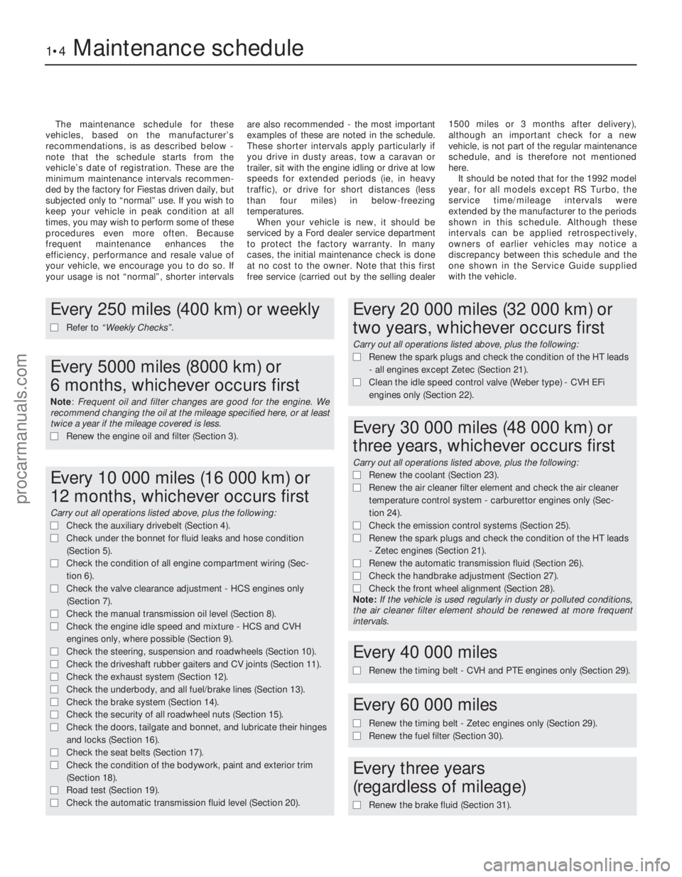
The maintenance schedule for these
vehicles, based on the manufacturer’s
recommendations, is as described below -
note that the schedule starts from the
vehicle’s date of registration. These are the
minimum maintenance intervals recommen-
ded by the factory for Fiestas driven daily, but
subjected only to “normal” use. If you wish to
keep your vehicle in peak condition at all
times, you may wish to perform some of these
procedures even more often. Because
frequent maintenance enhances the
efficiency, performance and resale value of
your vehicle, we encourage you to do so. If
your usage is not “normal”, shorter intervals are also recommended - the most important
examples of these are noted in the schedule.
These shorter intervals apply particularly if
you drive in dusty areas, tow a caravan or
trailer, sit with the engine idling or drive at low
speeds for extended periods (ie, in heavy
traffic), or drive for short distances (less
than four miles) in below-freezing
temperatures.
When your vehicle is new, it should be
serviced by a Ford dealer service department
to protect the factory warranty. In many
cases, the initial maintenance check is done
at no cost to the owner. Note that this first
free service (carried out by the selling dealer 1500 miles or 3 months after delivery),
although an important check for a new
vehicle, is not part of the regular maintenance
schedule, and is therefore not mentioned
here.
It should be noted that for the 1992 model
year, for all models except RS Turbo, the
service time/mileage intervals were
extended by the manufacturer to the periods
shown in this schedule. Although these
intervals can be applied retrospectively,
owners of earlier vehicles may notice a
discrepancy between this schedule and the
one shown in the Service Guide supplied
with the vehicle.
1•4Maintenance schedule
1595Ford Fiesta Remake
Every 250 miles (400 km) or weekly
m
m Refer to “Weekly Checks” .
Every 5000 miles (8000 km) or
6 months, whichever occurs first
Note: Frequent oil and filter changes are good for the engine. We
recommend changing the oil at the mileage specified here, or at least
twice a year if the mileage covered is less.
m m Renew the engine oil and filter (Section 3).
Every 10 000 miles (16 000 km) or
12 months, whichever occurs first
Carry out all operations listed above, plus the following:
m mCheck the auxiliary drivebelt (Section 4).
m
m Check under the bonnet for fluid leaks and hose condition
(Section 5).
m
m Check the condition of all engine compartment wiring (Sec-
tion 6).
m
m Check the valve clearance adjustment - HCS engines only
(Section 7).
m
m Check the manual transmission oil level (Section 8).
m
m Check the engine idle speed and mixture - HCS and CVH
engines only, where possible (Section 9).
m
m Check the steering, suspension and roadwheels (Section 10).
m
m Check the driveshaft rubber gaiters and CV joints (Section 11).
m
m Check the exhaust system (Section 12).
m
m Check the underbody, and all fuel/brake lines (Section 13).
m
m Check the brake system (Section 14).
m
m Check the security of all roadwheel nuts (Section 15).
m
m Check the doors, tailgate and bonnet, and lubricate their hinges
and locks (Section 16).
m
m Check the seat belts (Section 17).
m
m Check the condition of the bodywork, paint and exterior trim
(Section 18).
m
m Road test (Section 19).
m
m Check the automatic transmission fluid level (Section 20).
Every 20 000 miles (32 000 km) or
two years, whichever occurs first
Carry out all operations listed above, plus the following:
m mRenew the spark plugs and check the condition of the HT leads
- all engines except Zetec (Section 21).
m
m Clean the idle speed control valve (Weber type) - CVH EFi
engines only (Section 22).
Every 30 000 miles (48 000 km) or
three years, whichever occurs first
Carry out all operations listed above, plus the following:
m m Renew the coolant (Section 23).
m
m Renew the air cleaner filter element and check the air cleaner
temperature control system - carburettor engines only (Sec-
tion 24).
m m Check the emission control systems (Section 25).
m
m Renew the spark plugs and check the condition of the HT leads
- Zetec engines (Section 21).
m
m Renew the automatic transmission fluid (Section 26).
m
m Check the handbrake adjustment (Section 27).
m
m Check the front wheel alignment (Section 28).
Note: If the vehicle is used regularly in dusty or polluted conditions,
the air cleaner filter element should be renewed at more frequent
intervals.
Every 40 000 miles
m
m Renew the timing belt - CVH and PTE engines only (Section 29).
Every 60 000 miles
m
mRenew the timing belt - Zetec engines only (Section 29).
m
m Renew the fuel filter (Section 30).
Every three years
(regardless of mileage)
m m Renew the brake fluid (Section 31).
procarmanuals.com
http://vnx.su
Page 14 of 296
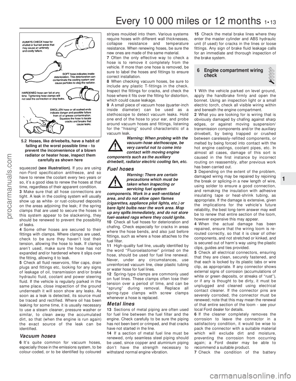
squeezed (see illustration) . If you are using
non-Ford specification antifreeze, and so
have to renew the coolant every two years or
so, it’s a good idea to renew the hoses at that
time, regardless of their apparent condition.
3 Make sure that all hose connections are
tight. A leak in the cooling system will usually
show up as white- or rust-coloured deposits
on the areas adjoining the leak; if the spring
clamps that are used to secure the hoses in
this system appear to be slackening, they
should be renewed to prevent the possibility
of leaks.
4 Some other hoses are secured to their
fittings with clamps. Where clamps are used,
check to be sure they haven’t lost their
tension, allowing the hose to leak. If clamps
aren’t used, make sure the hose has not
expanded and/or hardened where it slips over
the fitting, allowing it to leak.
5 Check all fluid reservoirs, filler caps, drain
plugs and fittings etc, looking for any signs
of leakage of oil, transmission and/or brake
hydraulic fluid, coolant and power steering
fluid. If the vehicle is regularly parked in the
same place, close inspection of the ground
underneath it will soon show any leaks. As
soon as a leak is detected, its source must
be traced and rectified. Where oil has been
leaking for some time, it is usually necessary
to use a steam cleaner, pressure washer or
similar, to clean away the accumulated
dirt, so that (when the engine is run again)
the exact source of the leak can be
identified.
Vacuum hoses
6 It’s quite common for vacuum hoses,
especially those in the emissions system, to be
colour-coded, or to be identified by coloured stripes moulded into them. Various systems
require hoses with different wall thicknesses,
collapse resistance and temperature
resistance. When renewing hoses, be sure the
new ones are made of the same material.
7
Often the only effective way to check a
hose is to remove it completely from the
vehicle. If more than one hose is removed, be
sure to label the hoses and fittings to ensure
correct installation.
8 When checking vacuum hoses, be sure to
include any plastic T-fittings in the check.
Inspect the fittings for cracks, and check the
hose where it fits over the fitting for distortion,
which could cause leakage.
9 A small piece of vacuum hose (quarter-inch
inside diameter) can be used as a
stethoscope to detect vacuum leaks. Hold
one end of the hose to your ear, and probe
around vacuum hoses and fittings, listening
for the “hissing” sound characteristic of a
vacuum leak. Warning: When probing with the
vacuum-hose stethoscope, be
very careful not to come into
contact with moving engine
components such as the auxiliary
drivebelt, radiator electric cooling fan, etc.
Fuel hoses
Warning: There are certain
precautions which must be
taken when inspecting or
servicing fuel system
components. Work in a well-ventilated
area, and do not allow open flames
(cigarettes, appliance pilot lights, etc.) or
bare light bulbs near the work area. Mop
up any spills immediately, and do not store
fuel-soaked rags where they could ignite.
10 Check all fuel hoses for deterioration and
chafing. Check especially for cracks in areas
where the hose bends, and also just before
fittings, such as where a hose attaches to the
fuel filter.
11 High-quality fuel line, usually identified by
the word “Fluoroelastomer” printed on the
hose, should be used for fuel line renewal.
Never, under any circumstances, use
unreinforced vacuum line, clear plastic tubing
or water hose for fuel lines.
12 Spring- type clamps are commonly used
on fuel lines. These clamps often lose their
tension over a period of time, and can be
“sprung” during removal. Replace all
spring- type clamps with screw clamps
whenever a hose is replaced.
Metal lines
13 Sections of metal piping are often used
for fuel line between the fuel filter and the
engine. Check carefully to be sure the piping
has not been bent or crimped, and that cracks
have not started in the line.
14 If a section of metal fuel line must be
renewed, only seamless steel piping should
be used, since copper and aluminium piping
don’t have the strength necessary to
withstand normal engine vibration. 15
Check the metal brake lines where they
enter the master cylinder and ABS hydraulic
unit (if used) for cracks in the lines or loose
fittings. Any sign of brake fluid leakage calls
for an immediate and thorough inspection of
the brake system.
6 Engine compartment wiring check
1
1With the vehicle parked on level ground,
apply the handbrake firmly and open the
bonnet. Using an inspection light or a small
electric torch, check all visible wiring within
and beneath the engine compartment.
2 What you are looking for is wiring that is
obviously damaged by chafing against sharp
edges, or against moving suspension/
transmission components and/or the auxiliary
drivebelt, by being trapped or crushed
between carelessly-refitted components, or
melted by being forced into contact with the
hot engine castings, coolant pipes, etc. In
almost all cases, damage of this sort is
caused in the first instance by incorrect
routing on reassembly, after previous work
has been carried out.
3 Depending on the extent of the problem,
damaged wiring may be repaired by rejoining
the break or splicing-in a new length of wire,
using solder to ensure a good connection,
and remaking the insulation with adhesive
insulating tape or heat-shrink tubing, as
appropriate. If the damage is extensive, given
the implications for the vehicle’s future
reliability, the best long-term answer may well
be to renew that entire section of the loom,
however expensive this may appear.
4 When the actual damage has been
repaired, ensure that the wiring loom is re-
routed correctly, so that it is clear of other
components, and not stretched or kinked, and
is secured out of harm’s way using the plastic
clips, guides and ties provided.
5 Check all electrical connectors, ensuring
that they are clean, securely fastened, and
that each is locked by its plastic tabs or wire
clip, as appropriate. If any connector shows
external signs of corrosion (accumulations of
white or green deposits, or streaks of “rust”),
or if any is thought to be dirty, it must be
unplugged and cleaned using electrical
contact cleaner. If the connector pins are
severely corroded, the connector must be
renewed; note that this may mean the renewal
of that entire section of the loom - see your
local Ford dealer for details.
6 If the cleaner completely removes the
corrosion to leave the connector in a
satisfactory condition, it would be wise to
pack the connector with a suitable material
which will exclude dirt and moisture,
preventing the corrosion from occurring
again; a Ford dealer may be able to
recommend a suitable product.
7 Check the condition of the battery
Every 10 000 miles or 12 months1•13
5.2 Hoses, like drivebelts, have a habit of
failing at the worst possible time - to
prevent the inconvenience of a blown radiator or heater hose, inspect them
carefully as shown here
1
1595Ford Fiesta Remakeprocarmanuals.com
http://vnx.su
Page 24 of 296
SEFi fuel injection models
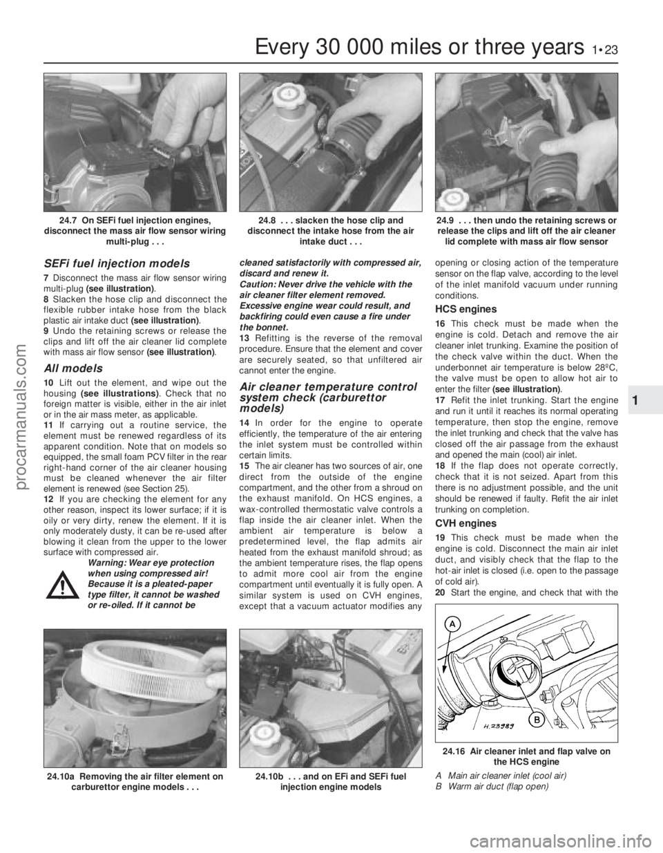
7Disconnect the mass air flow sensor wiring
multi-plug (see illustration) .
8 Slacken the hose clip and disconnect the
flexible rubber intake hose from the black
plastic air intake duct (see illustration).
9 Undo the retaining screws or release the
clips and lift off the air cleaner lid complete
with mass air flow sensor (see illustration).
All models
10Lift out the element, and wipe out the
housing (see illustrations) . Check that no
foreign matter is visible, either in the air inlet
or in the air mass meter, as applicable.
11 If carrying out a routine service, the
element must be renewed regardless of its
apparent condition. Note that on models so
equipped, the small foam PCV filter in the rear
right-hand corner of the air cleaner housing
must be cleaned whenever the air filter
element is renewed (see Section 25).
12 If you are checking the element for any
other reason, inspect its lower surface; if it is
oily or very dirty, renew the element. If it is
only moderately dusty, it can be re-used after
blowing it clean from the upper to the lower
surface with compressed air. Warning: Wear eye protection
when using compressed air!
Because it is a pleated-paper
type filter, it cannot be washed
or re-oiled. If it cannot be cleaned satisfactorily with compressed air,
discard and renew it.
Caution: Never drive the vehicle with the
air cleaner filter element removed.
Excessive engine wear could result, and
backfiring could even cause a fire under
the bonnet.
13
Refitting is the reverse of the removal
procedure. Ensure that the element and cover
are securely seated, so that unfiltered air
cannot enter the engine.Air cleaner temperature control
system check (carburettor
models)
14 In order for the engine to operate
efficiently, the temperature of the air entering
the inlet system must be controlled within
certain limits.
15 The air cleaner has two sources of air, one
direct from the outside of the engine
compartment, and the other from a shroud on
the exhaust manifold. On HCS engines, a
wax-controlled thermostatic valve controls a
flap inside the air cleaner inlet. When the
ambient air temperature is below a
predetermined level, the flap admits air
heated from the exhaust manifold shroud; as
the ambient temperature rises, the flap opens
to admit more cool air from the engine
compartment until eventually it is fully open. A
similar system is used on CVH engines,
except that a vacuum actuator modifies any opening or closing action of the temperature
sensor on the flap valve, according to the level
of the inlet manifold vacuum under running
conditions.
HCS engines
16
This check must be made when the
engine is cold. Detach and remove the air
cleaner inlet trunking. Examine the position of
the check valve within the duct. When the
underbonnet air temperature is below 28ºC,
the valve must be open to allow hot air to
enter the filter (see illustration) .
17 Refit the inlet trunking. Start the engine
and run it until it reaches its normal operating
temperature, then stop the engine, remove
the inlet trunking and check that the valve has
closed off the air passage from the exhaust
and opened the main (cool) air inlet.
18 If the flap does not operate correctly,
check that it is not seized. Apart from this
there is no adjustment possible, and the unit
should be renewed if faulty. Refit the air inlet
trunking on completion.
CVH engines
19 This check must be made when the
engine is cold. Disconnect the main air inlet
duct, and visibly check that the flap to the
hot-air inlet is closed (i.e. open to the passage
of cold air).
20 Start the engine, and check that with the
Every 30 000 miles or three years1•23
24.9 . . . then undo the retaining screws or
release the clips and lift off the air cleaner lid complete with mass air flow sensor24.8 . . . slacken the hose clip and
disconnect the intake hose from the air intake duct . . .24.7 On SEFi fuel injection engines,
disconnect the mass air flow sensor wiring multi-plug . . .
24.16 Air cleaner inlet and flap valve onthe HCS engine
A Main air cleaner inlet (cool air)
B Warm air duct (flap open)
24.10b . . . and on EFi and SEFi fuel injection engine models24.10a Removing the air filter element oncarburettor engine models . . .
1
1595Ford Fiesta Remakeprocarmanuals.com
http://vnx.su
Page 32 of 296
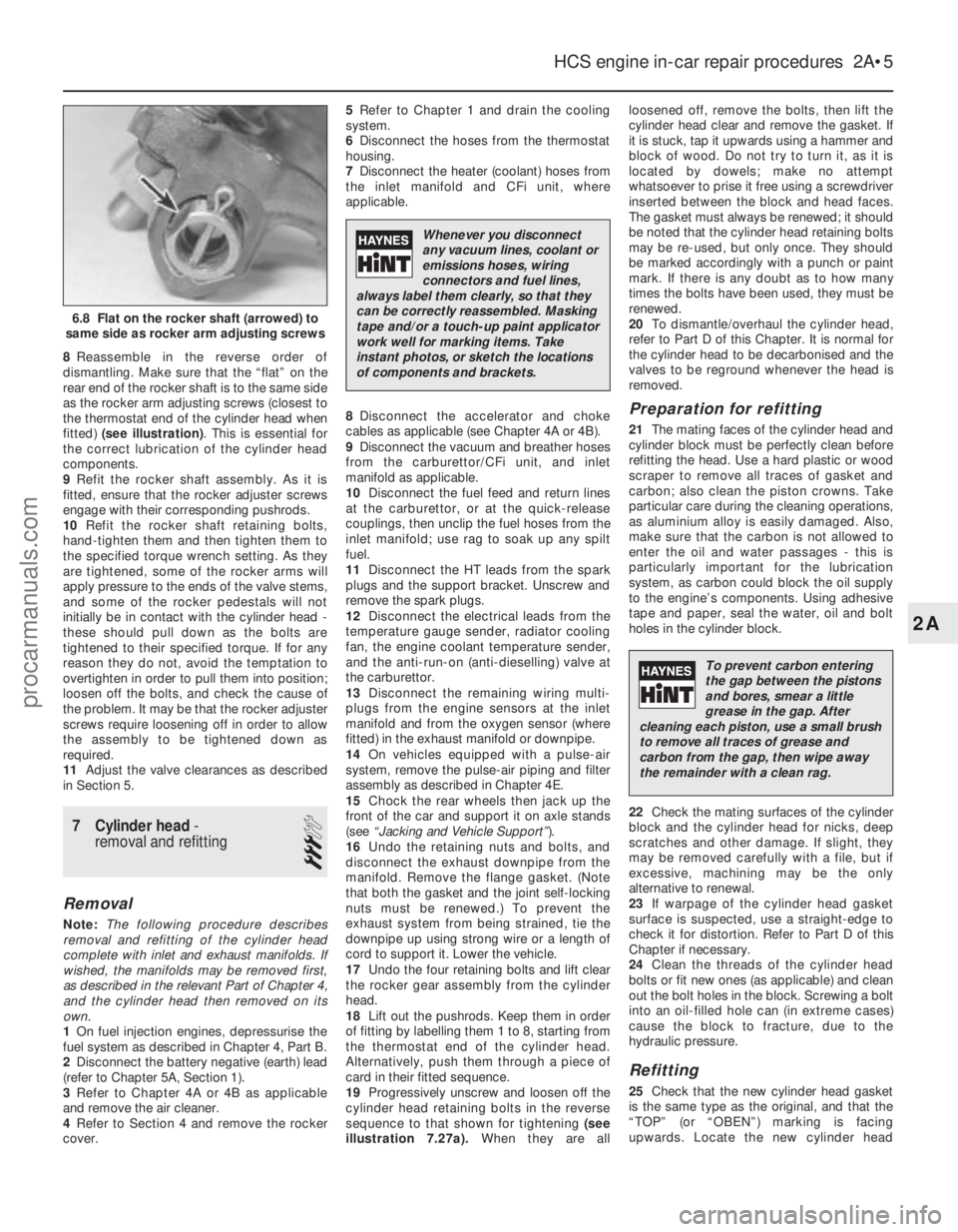
8Reassemble in the reverse order of
dismantling. Make sure that the “flat” on the
rear end of the rocker shaft is to the same side
as the rocker arm adjusting screws (closest to
the thermostat end of the cylinder head when
fitted) (see illustration) . This is essential for
the correct lubrication of the cylinder head
components.
9 Refit the rocker shaft assembly. As it is
fitted, ensure that the rocker adjuster screws
engage with their corresponding pushrods.
10 Refit the rocker shaft retaining bolts,
hand-tighten them and then tighten them to
the specified torque wrench setting. As they
are tightened, some of the rocker arms will
apply pressure to the ends of the valve stems,
and some of the rocker pedestals will not
initially be in contact with the cylinder head -
these should pull down as the bolts are
tightened to their specified torque. If for any
reason they do not, avoid the temptation to
overtighten in order to pull them into position;
loosen off the bolts, and check the cause of
the problem. It may be that the rocker adjuster
screws require loosening off in order to allow
the assembly to be tightened down as
required.
11 Adjust the valve clearances as described
in Section 5.
7 Cylinder head -
removal and refitting
3
Removal
Note: The following procedure describes
removal and refitting of the cylinder head
complete with inlet and exhaust manifolds. If
wished, the manifolds may be removed first,
as described in the relevant Part of Chapter 4,
and the cylinder head then removed on its
own.
1 On fuel injection engines, depressurise the
fuel system as described in Chapter 4, Part B.
2 Disconnect the battery negative (earth) lead
(refer to Chapter 5A, Section 1).
3 Refer to Chapter 4A or 4B as applicable
and remove the air cleaner.
4 Refer to Section 4 and remove the rocker
cover. 5
Refer to Chapter 1 and drain the cooling
system.
6 Disconnect the hoses from the thermostat
housing.
7 Disconnect the heater (coolant) hoses from
the inlet manifold and CFi unit, where
applicable.
8 Disconnect the accelerator and choke
cables as applicable (see Chapter 4A or 4B).
9 Disconnect the vacuum and breather hoses
from the carburettor/CFi unit, and inlet
manifold as applicable.
10 Disconnect the fuel feed and return lines
at the carburettor, or at the quick-release
couplings, then unclip the fuel hoses from the
inlet manifold; use rag to soak up any spilt
fuel.
11 Disconnect the HT leads from the spark
plugs and the support bracket. Unscrew and
remove the spark plugs.
12 Disconnect the electrical leads from the
temperature gauge sender, radiator cooling
fan, the engine coolant temperature sender,
and the anti-run-on (anti-dieselling) valve at
the carburettor.
13 Disconnect the remaining wiring multi-
plugs from the engine sensors at the inlet
manifold and from the oxygen sensor (where
fitted) in the exhaust manifold or downpipe.
14 On vehicles equipped with a pulse-air
system, remove the pulse-air piping and filter
assembly as described in Chapter 4E.
15 Chock the rear wheels then jack up the
front of the car and support it on axle stands
(see “Jacking and Vehicle Support” ).
16 Undo the retaining nuts and bolts, and
disconnect the exhaust downpipe from the
manifold. Remove the flange gasket. (Note
that both the gasket and the joint self-locking
nuts must be renewed.) To prevent the
exhaust system from being strained, tie the
downpipe up using strong wire or a length of
cord to support it. Lower the vehicle.
17 Undo the four retaining bolts and lift clear
the rocker gear assembly from the cylinder
head.
18 Lift out the pushrods. Keep them in order
of fitting by labelling them 1 to 8, starting from
the thermostat end of the cylinder head.
Alternatively, push them through a piece of
card in their fitted sequence.
19 Progressively unscrew and loosen off the
cylinder head retaining bolts in the reverse
sequence to that shown for tightening (see
illustration 7.27a). When they are all loosened off, remove the bolts, then lift the
cylinder head clear and remove the gasket. If
it is stuck, tap it upwards using a hammer and
block of wood. Do not try to turn it, as it is
located by dowels; make no attempt
whatsoever to prise it free using a screwdriver
inserted between the block and head faces.
The gasket must always be renewed; it should
be noted that the cylinder head retaining bolts
may be re-used, but only once. They should
be marked accordingly with a punch or paint
mark. If there is any doubt as to how many
times the bolts have been used, they must be
renewed.
20
To dismantle/overhaul the cylinder head,
refer to Part D of this Chapter. It is normal for
the cylinder head to be decarbonised and the
valves to be reground whenever the head is
removed.
Preparation for refitting
21 The mating faces of the cylinder head and
cylinder block must be perfectly clean before
refitting the head. Use a hard plastic or wood
scraper to remove all traces of gasket and
carbon; also clean the piston crowns. Take
particular care during the cleaning operations,
as aluminium alloy is easily damaged. Also,
make sure that the carbon is not allowed to
enter the oil and water passages - this is
particularly important for the lubrication
system, as carbon could block the oil supply
to the engine’s components. Using adhesive
tape and paper, seal the water, oil and bolt
holes in the cylinder block.
22 Check the mating surfaces of the cylinder
block and the cylinder head for nicks, deep
scratches and other damage. If slight, they
may be removed carefully with a file, but if
excessive, machining may be the only
alternative to renewal.
23 If warpage of the cylinder head gasket
surface is suspected, use a straight-edge to
check it for distortion. Refer to Part D of this
Chapter if necessary.
24 Clean the threads of the cylinder head
bolts or fit new ones (as applicable) and clean
out the bolt holes in the block. Screwing a bolt
into an oil-filled hole can (in extreme cases)
cause the block to fracture, due to the
hydraulic pressure.
Refitting
25 Check that the new cylinder head gasket
is the same type as the original, and that the
“TOP” (or “OBEN”) marking is facing
upwards. Locate the new cylinder head
HCS engine in-car repair procedures 2A•5
6.8 Flat on the rocker shaft (arrowed) to
same side as rocker arm adjusting screws
2A
1595Ford Fiesta Remake
Whenever you disconnect
any vacuum lines, coolant or
emissions hoses, wiring
connectors and fuel lines,
always label them clearly, so that they
can be correctly reassembled. Masking
tape and/or a touch-up paint applicator
work well for marking items. Take
instant photos, or sketch the locations
of components and brackets.
To prevent carbon entering
the gap between the pistons
and bores, smear a little
grease in the gap. After
cleaning each piston, use a small brush
to remove all traces of grease and
carbon from the gap, then wipe away
the remainder with a clean rag.
procarmanuals.com
http://vnx.su
Page 34 of 296
cover). Using a new gasket, fit the timing
chain cover, centring it with the aid of the
crankshaft pulley - lubricate the seal contact
surfaces beforehand. Refit and tighten the
retaining bolts but, where applicable, leave
out the timing cover bolt which also secures
the water pump at this stage.
8Where applicable, refit the water pump as
described in Chapter 3.
9 Refit the crankshaft pulley as described in
the previous Section.
10 Refit the sump as described in Section 11.
10Timing chain, sprockets and
tensioner - removal,
inspection and refitting
3
Removal
1 Remove the timing chain cover as
described in the previous Section.
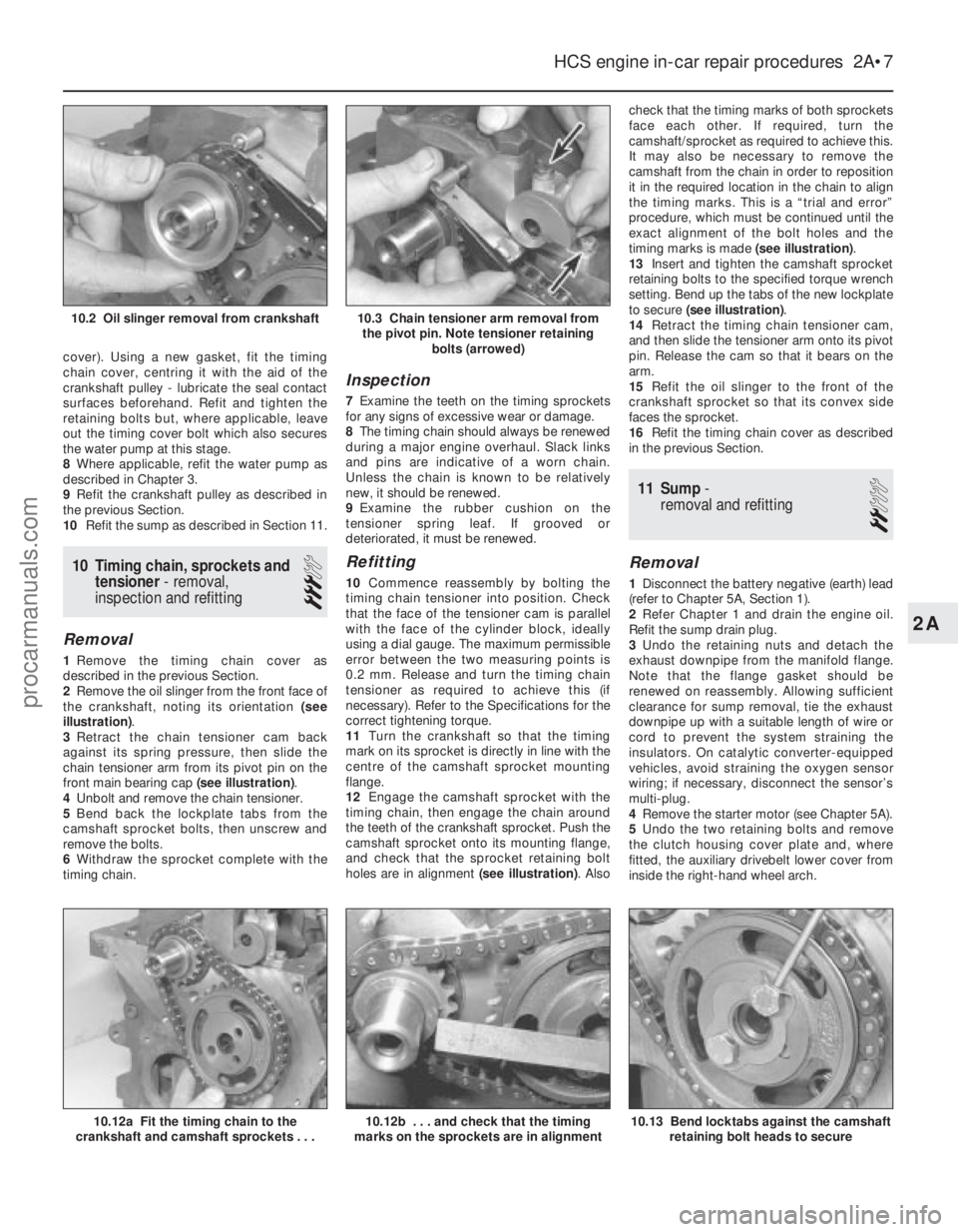
2 Remove the oil slinger from the front face of
the crankshaft, noting its orientation (see
illustration) .
3 Retract the chain tensioner cam back
against its spring pressure, then slide the
chain tensioner arm from its pivot pin on the
front main bearing cap (see illustration).
4 Unbolt and remove the chain tensioner.
5 Bend back the lockplate tabs from the
camshaft sprocket bolts, then unscrew and
remove the bolts.
6 Withdraw the sprocket complete with the
timing chain.
Inspection
7 Examine the teeth on the timing sprockets
for any signs of excessive wear or damage.
8 The timing chain should always be renewed
during a major engine overhaul. Slack links
and pins are indicative of a worn chain.
Unless the chain is known to be relatively
new, it should be renewed.
9 Examine the rubber cushion on the
tensioner spring leaf. If grooved or
deteriorated, it must be renewed.
Refitting
10 Commence reassembly by bolting the
timing chain tensioner into position. Check
that the face of the tensioner cam is parallel
with the face of the cylinder block, ideally
using a dial gauge. The maximum permissible
error between the two measuring points is
0.2 mm. Release and turn the timing chain
tensioner as required to achieve this (if
necessary). Refer to the Specifications for the
correct tightening torque.
11 Turn the crankshaft so that the timing
mark on its sprocket is directly in line with the
centre of the camshaft sprocket mounting
flange.
12 Engage the camshaft sprocket with the
timing chain, then engage the chain around
the teeth of the crankshaft sprocket. Push the
camshaft sprocket onto its mounting flange,
and check that the sprocket retaining bolt
holes are in alignment (see illustration). Alsocheck that the timing marks of both sprockets
face each other. If required, turn the
camshaft/sprocket as required to achieve this.
It may also be necessary to remove the
camshaft from the chain in order to reposition
it in the required location in the chain to align
the timing marks. This is a “trial and error”
procedure, which must be continued until the
exact alignment of the bolt holes and the
timing marks is made
(see illustration).
13 Insert and tighten the camshaft sprocket
retaining bolts to the specified torque wrench
setting. Bend up the tabs of the new lockplate
to secure (see illustration) .
14 Retract the timing chain tensioner cam,
and then slide the tensioner arm onto its pivot
pin. Release the cam so that it bears on the
arm.
15 Refit the oil slinger to the front of the
crankshaft sprocket so that its convex side
faces the sprocket.
16 Refit the timing chain cover as described
in the previous Section.
11 Sump -
removal and refitting
2
Removal
1 Disconnect the battery negative (earth) lead
(refer to Chapter 5A, Section 1).
2 Refer Chapter 1 and drain the engine oil.
Refit the sump drain plug.
3 Undo the retaining nuts and detach the
exhaust downpipe from the manifold flange.
Note that the flange gasket should be
renewed on reassembly. Allowing sufficient
clearance for sump removal, tie the exhaust
downpipe up with a suitable length of wire or
cord to prevent the system straining the
insulators. On catalytic converter-equipped
vehicles, avoid straining the oxygen sensor
wiring; if necessary, disconnect the sensor’s
multi-plug.
4 Remove the starter motor (see Chapter 5A).
5 Undo the two retaining bolts and remove
the clutch housing cover plate and, where
fitted, the auxiliary drivebelt lower cover from
inside the right-hand wheel arch.
HCS engine in-car repair procedures 2A•7
10.12a Fit the timing chain to the
crankshaft and camshaft sprockets . . .
10.3 Chain tensioner arm removal from the pivot pin. Note tensioner retaining bolts (arrowed)10.2 Oil slinger removal from crankshaft
10.13 Bend locktabs against the camshaftretaining bolt heads to secure10.12b . . . and check that the timing
marks on the sprockets are in alignment
2A
1595Ford Fiesta Remakeprocarmanuals.com
http://vnx.su
Page 48 of 296
23Refer to the procedure in Section 9 when
refitting the camshaft sprocket.
24 Refit and tension the timing belt as
described in Section 8.
25 Lubricate the hydraulic tappets with
hypoid oil before refitting them into their
original locations in the cylinder head.
26 Lubricate and refit the rocker arms and
guides in their original sequence, use new
nuts and tighten them to the specified torque
setting. It is essential, before each rocker arm
is installed and its nut tightened, that the
respective cam follower is positioned at its
lowest point (in contact with the cam base
circle). Turn the cam (using the crankshaft
pulley bolt) as necessary to achieve this.
27 Refit the rocker cover as described in
Section 4.
28 Refit the remaining components with
reference to the relevant Sections in this
Chapter or elsewhere in the manual.
29 On completion, reconnect the battery
negative lead.
12 Cylinder head -
removal and refitting
4
Removal
Note: The following procedure describes
removal and refitting of the cylinder head
complete with inlet and exhaust manifolds. If
wished, the manifolds may be removed first,
as described in the relevant Part of Chapter 4,
and the cylinder head then removed on its
own.
1 On fuel-injected engines, depressurise the
fuel system as described in Chapter 4B or 4C.
2 Disconnect the battery negative (earth) lead
(refer to Chapter 5A, Section 1).
3 Refer to Chapter 1 and drain the cooling
system. 4
Remove the rocker cover as described in
Section 4.
5 Disconnect the accelerator and choke
cables as applicable (refer to the relevant Part
of Chapter 4).
6 Loosen off the retaining clips and
disconnect the upper coolant hose, the
expansion tank hose and the heater hose
from the thermostat housing. Also disconnect
the heater hose from the inlet manifold.
7 On CFi models, disconnect the heated
coolant hose from the injector unit.
8 On EFi and SEFi models, disconnect the
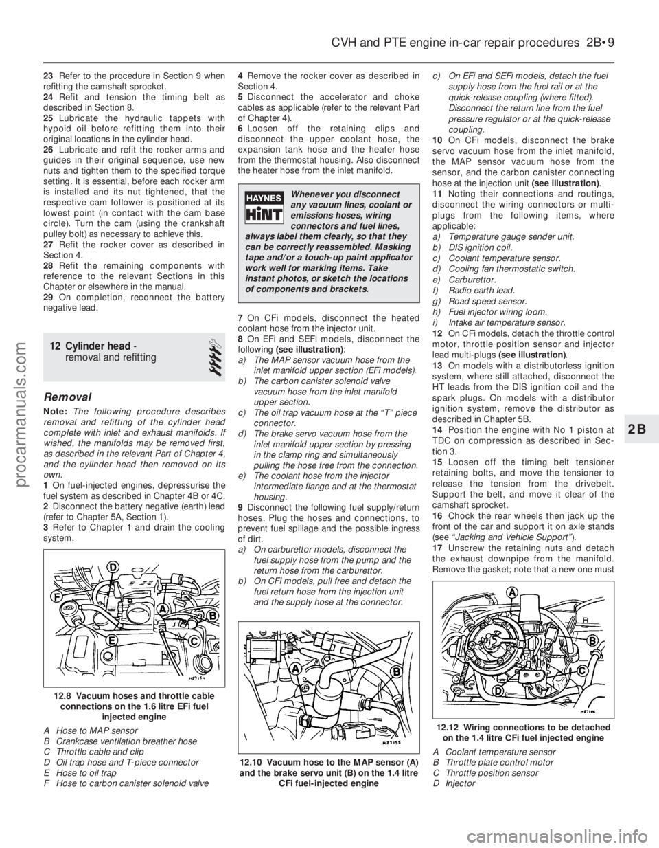
following (see illustration) :
a) The MAP sensor vacuum hose from the inlet manifold upper section (EFi models).
b) The carbon canister solenoid valve
vacuum hose from the inlet manifold
upper section.
c) The oil trap vacuum hose at the “T” piece
connector.
d) The brake servo vacuum hose from the
inlet manifold upper section by pressing
in the clamp ring and simultaneously
pulling the hose free from the connection.
e) The coolant hose from the injector
intermediate flange and at the thermostat
housing.
9 Disconnect the following fuel supply/return
hoses. Plug the hoses and connections, to
prevent fuel spillage and the possible ingress
of dirt.
a) On carburettor models, disconnect the fuel supply hose from the pump and the
return hose from the carburettor.
b) On CFi models, pull free and detach the
fuel return hose from the injection unit
and the supply hose at the connector. c) On EFi and SEFi models, detach the fuel
supply hose from the fuel rail or at the
quick-release coupling (where fitted).
Disconnect the return line from the fuel
pressure regulator or at the quick-release
coupling.
10 On CFi models, disconnect the brake
servo vacuum hose from the inlet manifold,
the MAP sensor vacuum hose from the
sensor, and the carbon canister connecting
hose at the injection unit (see illustration).
11 Noting their connections and routings,
disconnect the wiring connectors or multi-
plugs from the following items, where
applicable:
a) Temperature gauge sender unit.
b) DIS ignition coil.
c) Coolant temperature sensor.
d) Cooling fan thermostatic switch.
e) Carburettor.
f) Radio earth lead.
g) Road speed sensor.
h) Fuel injector wiring loom.
i) Intake air temperature sensor.
12 On CFi models, detach the throttle control
motor, throttle position sensor and injector
lead multi-plugs (see illustration) .
13 On models with a distributorless ignition
system, where still attached, disconnect the
HT leads from the DIS ignition coil and the
spark plugs. On models with a distributor
ignition system, remove the distributor as
described in Chapter 5B.
14 Position the engine with No 1 piston at
TDC on compression as described in Sec-
tion 3.
15 Loosen off the timing belt tensioner
retaining bolts, and move the tensioner to
release the tension from the drivebelt.
Support the belt, and move it clear of the
camshaft sprocket.
16 Chock the rear wheels then jack up the
front of the car and support it on axle stands
(see “Jacking and Vehicle Support” ).
17 Unscrew the retaining nuts and detach
the exhaust downpipe from the manifold.
Remove the gasket; note that a new one must
CVH and PTE engine in-car repair procedures 2B•9
12.12 Wiring connections to be detached on the 1.4 litre CFi fuel injected engine
A Coolant temperature sensor
B Throttle plate control motor
C Throttle position sensor
D Injector
12.10 Vacuum hose to the MAP sensor (A)
and the brake servo unit (B) on the 1.4 litre
CFi fuel-injected engine
12.8 Vacuum hoses and throttle cableconnections on the 1.6 litre EFi fuel injected engine
A Hose to MAP sensor
B Crankcase ventilation breather hose
C Throttle cable and clip
D Oil trap hose and T-piece connector
E Hose to oil trap
F Hose to carbon canister solenoid valve
2B
1595Ford Fiesta Remake
Whenever you disconnect
any vacuum lines, coolant or
emissions hoses, wiring
connectors and fuel lines,
always label them clearly, so that they
can be correctly reassembled. Masking
tape and/or a touch-up paint applicator
work well for marking items. Take
instant photos, or sketch the locations
of components and brackets.
procarmanuals.com
http://vnx.su
Page 64 of 296
5Disconnect the accelerator cable from the
throttle linkage as described in Chapter 4D.
Secure the cable clear of the engine/
transmission.
6 Remove the auxiliary drivebelt (see Chap-
ter 1).
7 Remove the three screws securing the
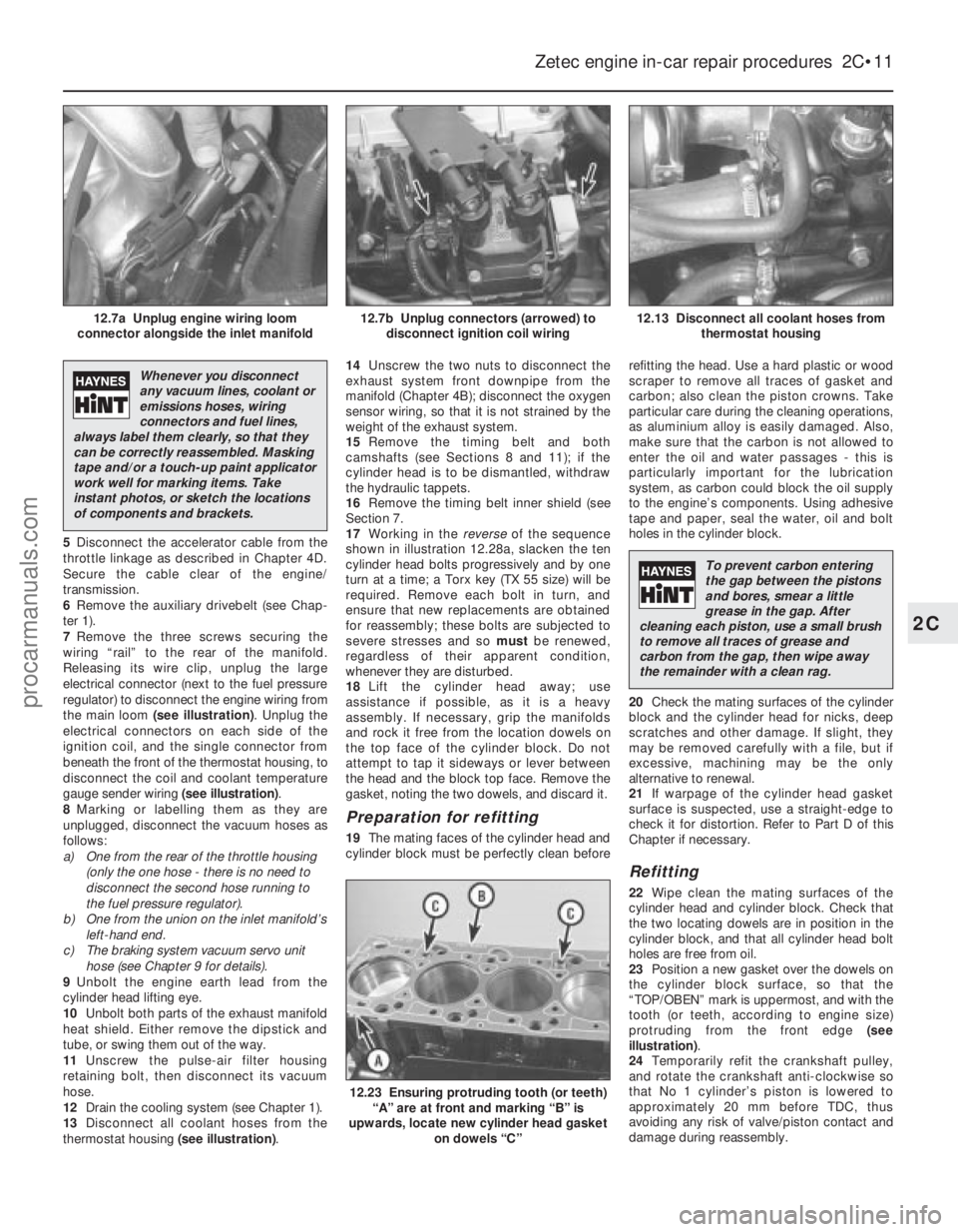
wiring “rail” to the rear of the manifold.
Releasing its wire clip, unplug the large
electrical connector (next to the fuel pressure
regulator) to disconnect the engine wiring from
the main loom (see illustration) . Unplug the
electrical connectors on each side of the
ignition coil, and the single connector from
beneath the front of the thermostat housing, to
disconnect the coil and coolant temperature
gauge sender wiring (see illustration).
8 Marking or labelling them as they are
unplugged, disconnect the vacuum hoses as
follows:
a) One from the rear of the throttle housing
(only the one hose - there is no need to
disconnect the second hose running to
the fuel pressure regulator).
b) One from the union on the inlet manifold’s
left-hand end.
c) The braking system vacuum servo unit hose (see Chapter 9 for details).
9 Unbolt the engine earth lead from the
cylinder head lifting eye.
10 Unbolt both parts of the exhaust manifold
heat shield. Either remove the dipstick and
tube, or swing them out of the way.
11 Unscrew the pulse-air filter housing
retaining bolt, then disconnect its vacuum
hose.
12 Drain the cooling system (see Chapter 1).
13 Disconnect all coolant hoses from the
thermostat housing (see illustration).14
Unscrew the two nuts to disconnect the
exhaust system front downpipe from the
manifold (Chapter 4B); disconnect the oxygen
sensor wiring, so that it is not strained by the
weight of the exhaust system.
15 Remove the timing belt and both
camshafts (see Sections 8 and 11); if the
cylinder head is to be dismantled, withdraw
the hydraulic tappets.
16 Remove the timing belt inner shield (see
Section 7.
17 Working in the reverseof the sequence
shown in illustration 12.28a, slacken the ten
cylinder head bolts progressively and by one
turn at a time; a Torx key (TX 55 size) will be
required. Remove each bolt in turn, and
ensure that new replacements are obtained
for reassembly; these bolts are subjected to
severe stresses and so mustbe renewed,
regardless of their apparent condition,
whenever they are disturbed.
18 Lift the cylinder head away; use
assistance if possible, as it is a heavy
assembly. If necessary, grip the manifolds
and rock it free from the location dowels on
the top face of the cylinder block. Do not
attempt to tap it sideways or lever between
the head and the block top face. Remove the
gasket, noting the two dowels, and discard it.
Preparation for refitting
19 The mating faces of the cylinder head and
cylinder block must be perfectly clean before refitting the head. Use a hard plastic or wood
scraper to remove all traces of gasket and
carbon; also clean the piston crowns. Take
particular care during the cleaning operations,
as aluminium alloy is easily damaged. Also,
make sure that the carbon is not allowed to
enter the oil and water passages - this is
particularly important for the lubrication
system, as carbon could block the oil supply
to the engine’s components. Using adhesive
tape and paper, seal the water, oil and bolt
holes in the cylinder block.
20
Check the mating surfaces of the cylinder
block and the cylinder head for nicks, deep
scratches and other damage. If slight, they
may be removed carefully with a file, but if
excessive, machining may be the only
alternative to renewal.
21 If warpage of the cylinder head gasket
surface is suspected, use a straight-edge to
check it for distortion. Refer to Part D of this
Chapter if necessary.
Refitting
22 Wipe clean the mating surfaces of the
cylinder head and cylinder block. Check that
the two locating dowels are in position in the
cylinder block, and that all cylinder head bolt
holes are free from oil.
23 Position a new gasket over the dowels on
the cylinder block surface, so that the
“TOP/OBEN” mark is uppermost, and with the
tooth (or teeth, according to engine size)
protruding from the front edge (see
illustration) .
24 Temporarily refit the crankshaft pulley,
and rotate the crankshaft anti-clockwise so
that No 1 cylinder’s piston is lowered to
approximately 20 mm before TDC, thus
avoiding any risk of valve/piston contact and
damage during reassembly.
Zetec engine in-car repair procedures 2C•11
12.13 Disconnect all coolant hoses from thermostat housing12.7b Unplug connectors (arrowed) todisconnect ignition coil wiring12.7a Unplug engine wiring loom
connector alongside the inlet manifold
12.23 Ensuring protruding tooth (or teeth) “A” are at front and marking “B” is
upwards, locate new cylinder head gasket on dowels “C”
2C
1595Ford Fiesta Remake
Whenever you disconnect
any vacuum lines, coolant or
emissions hoses, wiring
connectors and fuel lines,
always label them clearly, so that they
can be correctly reassembled. Masking
tape and/or a touch-up paint applicator
work well for marking items. Take
instant photos, or sketch the locations
of components and brackets.
To prevent carbon entering
the gap between the pistons
and bores, smear a little
grease in the gap. After
cleaning each piston, use a small brush
to remove all traces of grease and
carbon from the gap, then wipe away
the remainder with a clean rag.
procarmanuals.com
http://vnx.su