1989 FORD FIESTA fuel consumption
[x] Cancel search: fuel consumptionPage 43 of 296
complete turn, and all the markings should
now align.
7With the engine set at No 1 piston on TDC
compression, refit the crankshaft pulley cover,
lower the vehicle and refit the upper timing
belt cover.
4 Cylinder head rocker cover -
removal and refitting
2
Removal
1 Disconnect the battery negative (earth) lead
(refer to Chapter 5A, Section 1).
2 Remove the air cleaner assembly and air
inlet components as necessary for access as
described in the relevant Part of Chapter 4.
Disconnect the crankcase ventilation hose
from the rocker cover.
3 Remove the timing belt upper cover as
described in Section 7.
4 Referring to the relevant Part of Chapter 4
for details, disconnect the accelerator cable
from the throttle linkage and from the adjuster
bracket above the rocker cover. Position the
cable out of the way.
5 Where applicable, disconnect the choke
cable from the carburettor, referring to
Chapter 4A for details.
6 Unscrew and remove the rocker cover
retaining bolts and washers, then lift the cover
from the cylinder head. Note that a new
rocker cover gasket will be needed on
refitting.
Refitting
7 Before refitting the rocker cover, clean the
mating surfaces of both the cylinder head and
the cover.
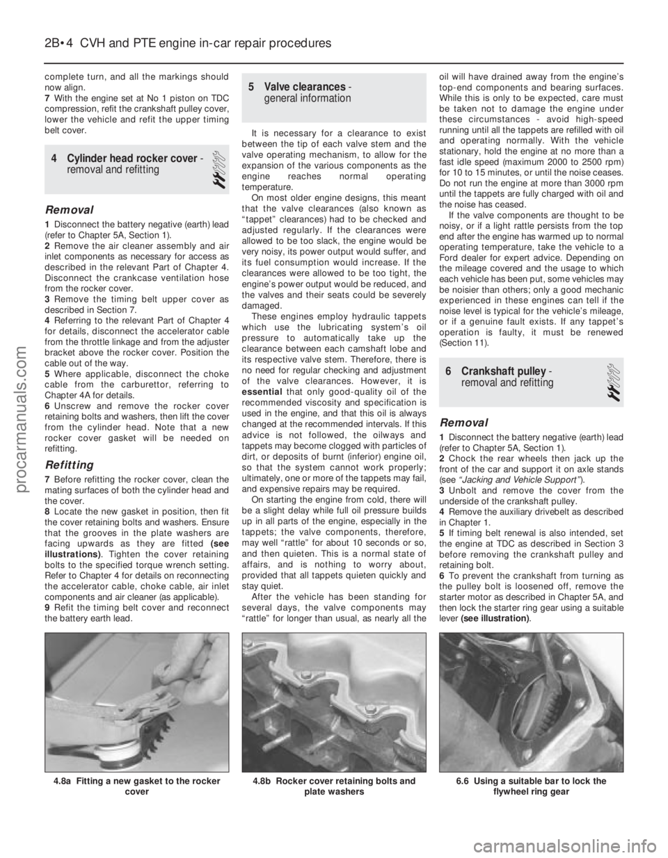
8 Locate the new gasket in position, then fit
the cover retaining bolts and washers. Ensure
that the grooves in the plate washers are
facing upwards as they are fitted (see
illustrations) . Tighten the cover retaining
bolts to the specified torque wrench setting.
Refer to Chapter 4 for details on reconnecting
the accelerator cable, choke cable, air inlet
components and air cleaner (as applicable).
9 Refit the timing belt cover and reconnect
the battery earth lead.
5 Valve clearances -
general information
It is necessary for a clearance to exist
between the tip of each valve stem and the
valve operating mechanism, to allow for the
expansion of the various components as the
engine reaches normal operating
temperature. On most older engine designs, this meant
that the valve clearances (also known as
“tappet” clearances) had to be checked and
adjusted regularly. If the clearances were
allowed to be too slack, the engine would be
very noisy, its power output would suffer, and
its fuel consumption would increase. If the
clearances were allowed to be too tight, the
engine’s power output would be reduced, and
the valves and their seats could be severely
damaged. These engines employ hydraulic tappets
which use the lubricating system’s oil
pressure to automatically take up the
clearance between each camshaft lobe and
its respective valve stem. Therefore, there is
no need for regular checking and adjustment
of the valve clearances. However, it is
essential that only good-quality oil of the
recommended viscosity and specification is
used in the engine, and that this oil is always
changed at the recommended intervals. If this
advice is not followed, the oilways and
tappets may become clogged with particles of
dirt, or deposits of burnt (inferior) engine oil,
so that the system cannot work properly;
ultimately, one or more of the tappets may fail,
and expensive repairs may be required. On starting the engine from cold, there will
be a slight delay while full oil pressure builds
up in all parts of the engine, especially in the
tappets; the valve components, therefore,
may well “rattle” for about 10 seconds or so,
and then quieten. This is a normal state of
affairs, and is nothing to worry about,
provided that all tappets quieten quickly and
stay quiet. After the vehicle has been standing for
several days, the valve components may
“rattle” for longer than usual, as nearly all the oil will have drained away from the engine’s
top-end components and bearing surfaces.
While this is only to be expected, care must
be taken not to damage the engine under
these circumstances - avoid high-speed
running until all the tappets are refilled with oil
and operating normally. With the vehicle
stationary, hold the engine at no more than a
fast idle speed (maximum 2000 to 2500 rpm)
for 10 to 15 minutes, or until the noise ceases.
Do not run the engine at more than 3000 rpm
until the tappets are fully charged with oil and
the noise has ceased.
If the valve components are thought to be
noisy, or if a light rattle persists from the top
end after the engine has warmed up to normal
operating temperature, take the vehicle to a
Ford dealer for expert advice. Depending on
the mileage covered and the usage to which
each vehicle has been put, some vehicles may
be noisier than others; only a good mechanic
experienced in these engines can tell if the
noise level is typical for the vehicle’s mileage,
or if a genuine fault exists. If any tappet’s
operation is faulty, it must be renewed
(Section 11).
6 Crankshaft pulley -
removal and refitting
2
Removal
1 Disconnect the battery negative (earth) lead
(refer to Chapter 5A, Section 1).
2 Chock the rear wheels then jack up the
front of the car and support it on axle stands
(see “Jacking and Vehicle Support” ).
3 Unbolt and remove the cover from the
underside of the crankshaft pulley.
4 Remove the auxiliary drivebelt as described
in Chapter 1.
5 If timing belt renewal is also intended, set
the engine at TDC as described in Section 3
before removing the crankshaft pulley and
retaining bolt.
6 To prevent the crankshaft from turning as
the pulley bolt is loosened off, remove the
starter motor as described in Chapter 5A, and
then lock the starter ring gear using a suitable
lever (see illustration) .
2B•4 CVH and PTE engine in-car repair procedures
6.6 Using a suitable bar to lock the
flywheel ring gear4.8b Rocker cover retaining bolts and plate washers4.8a Fitting a new gasket to the rocker cover
1595Ford Fiesta Remakeprocarmanuals.com
http://vnx.su
Page 114 of 296
as described in Section 16. The power valve
assembly can also be removed in a similar
fashion.
5Prise free the accelerator pump discharge
tube, but take care not to damage it or the
carburettor body.
6 Remove the jets and emulsion tubes as
required, making careful notes of their
respective locations for reassembly.
Cleaning and inspection
7 Soak out the fuel in the float chamber using
a clean rag; this must be safely disposed of.
Clean the float chamber, jets, drillings and
passages with clean petrol. The careful use of
an air line (or footpump) is ideal to blow out
the upper and lower bodies. Never use a
piece of wire for cleaning purposes.
8 Examine all of the carburettor components
for signs of damage or wear, paying particular
attention to the diaphragms, throttle spindle
and plates, and needle valve. Renew all
diaphragms, sealing washers and gaskets as
a matter of course.
Reassembly
9 Refit the emulsion tubes and jets to their
locations as noted during dismantling.
10 Refit the accelerator pump discharge
tube.
11 Refit the accelerator pump and power
valve assemblies as described in Section 16.
12 Refit the needle valve and the float, and
adjust the float setting as described in Sec-
tion 14.
13 Locate a new gasket onto the mating
face, then refit the carburettor upper body to
the main body. As they are reassembled, take
care not to snag the float on the carburettor
main body. Fit and tighten the retaining
screws to secure.
14 On completion, refit the carburettor as
described in Section 15.
18 Carburettor (Weber TLDM) -
description
The carburettor is of twin venturi,
downdraught type, featuring a fixed size main
jet system, adjustable idle system, a
mechanically-operated accelerator pump, and
a vacuum-operated power valve. A manually-
operated cold start choke is fitted, and a
throttle kicker is used on certain models.
In order to comply with emission control
regulations and maintain good fuel
consumption, the main jets are calibrated to
suit the 1/4 to 3/4 throttle range. The power
valve is therefore only used to supply
additional fuel during full-throttle conditions. The accelerator pump is fitted to ensure a
smooth transmission from the idle circuit to
the main jet system. As the accelerator pedal
is depressed, a linkage moves the diaphragm
within the accelerator pump, and a small quantity of fuel is injected into the venturi, to
prevent a momentary weak mixture and
resultant engine hesitation.
The manually-operated choke features a
vacuum-operated pull-down mechanism
which controls the single choke plate under
certain vacuum conditions. On CTX automatic transmission models,
the throttle kicker acts as an idle speed
compensator for when the transmission shift
lever positions R, D or L are selected. The
throttle kicker is operated by vacuum supplied
from the inlet manifold. When the appropriate
transmission shift lever position is selected,
the throttle kicker control solenoid allows the
vacuum to pass to the throttle kicker which
maintains the idle speed by means of a
diaphragm and mechanical linkage. On manual transmission models, the
throttle kicker (when fitted) acts as a damper
by slowing down the closing action of the
throttle plate. Under deceleration, this
maintains the combustion of the air/fuel
mixture entering the cylinders, thus improving
the exhaust emission levels. A vacuum
sustain valve controls the carburettor-sourced
vacuum applied to the throttle kicker unit; this
allows the vacuum slowly to decay, allowing
normal engine idling speed to be achieved. An anti-dieseling (fuel cut-off) solenoid is
fitted to prevent the possibility of the engine
running on after the ignition is switched off. Idle speed and mixture adjustment
procedures are described in Chapter 1, but it
is important to note that accurate adjustments
can only be made using the necessary
equipment.
19 Carburettor (Weber TLDM) -
fast-idle speed adjustment
4
Note: Before carrying out any carburettor
adjustments, ensure that the spark plug gaps
are set as specified, and that all electrical and
vacuum connections are secure. To carry out
checks and adjustments, an accurate
tachometer and an exhaust gas analyser (CO
meter) will be required.
1 Check the idle speed and mixture settings are as specified (as described in Chapter 1).
These must be correct before
checking/adjusting the fast-idle speed.
2
With the engine at its normal operating
temperature, and a tachometer connected in
accordance with the manufacturer’s
instructions, switch the engine off, then
remove the air cleaner (if not already done) as
described in Section 2.
3 Actuate the choke by pulling the control
knob fully out, then start the engine and note
the engine fast-idle speed. Compare it with
the specified speed.
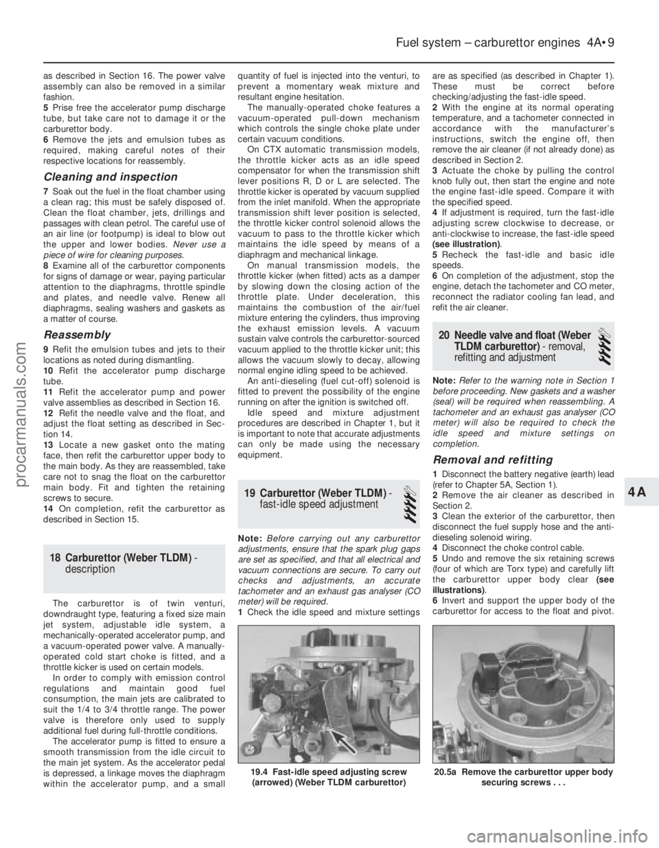
4 If adjustment is required, turn the fast-idle
adjusting screw clockwise to decrease, or
anti-clockwise to increase, the fast-idle speed
(see illustration) .
5 Recheck the fast-idle and basic idle
speeds.
6 On completion of the adjustment, stop the
engine, detach the tachometer and CO meter,
reconnect the radiator cooling fan lead, and
refit the air cleaner.
20 Needle valve and float (Weber
TLDM carburettor) - removal,
refitting and adjustment
4
Note: Refer to the warning note in Section 1
before proceeding. New gaskets and a washer
(seal) will be required when reassembling. A
tachometer and an exhaust gas analyser (CO
meter) will also be required to check the
idle speed and mixture settings on
completion.
Removal and refitting
1 Disconnect the battery negative (earth) lead
(refer to Chapter 5A, Section 1).
2 Remove the air cleaner as described in
Section 2.
3 Clean the exterior of the carburettor, then
disconnect the fuel supply hose and the anti-
dieseling solenoid wiring.
4 Disconnect the choke control cable.
5 Undo and remove the six retaining screws
(four of which are Torx type) and carefully lift
the carburettor upper body clear (see
illustrations) .
6 Invert and support the upper body of the
carburettor for access to the float and pivot.
Fuel system – carburettor engines 4A•9
19.4 Fast-idle speed adjusting screw (arrowed) (Weber TLDM carburettor)
4A
1595Ford Fiesta Remake
20.5a Remove the carburettor upper body securing screws . . .
procarmanuals.com
http://vnx.su
Page 272 of 296

REF•6Conversion Factors
1595 Ford Fiesta Remake
Length (distance)
Inches (in)x 25.4 = Millimetres (mm) x 0.0394 = Inches (in)
Feet (ft) x 0.305 = Metres (m) x 3.281 = Feet (ft)
Miles x 1.609 = Kilometres (km) x 0.621 = Miles
Volume (capacity)
Cubic inches (cu in; in3)x 16.387 = Cubic centimetres (cc; cm3) x 0.061 = Cubic inches (cu in; in3)
Imperial pints (Imp pt) x 0.568 = Litres (l) x 1.76 = Imperial pints (Imp pt)
Imperial quarts (Imp qt) x 1.137 = Litres (l) x 0.88 = Imperial quarts (Imp qt)
Imperial quarts (Imp qt) x 1.201 = US quarts (US qt) x 0.833 = Imperial quarts (Imp qt)
US quarts (US qt) x 0.946 = Litres (l) x 1.057 = US quarts (US qt)
Imperial gallons (Imp gal) x 4.546 = Litres (l) x 0.22 = Imperial gallons (Imp gal)
Imperial gallons (Imp gal) x 1.201 = US gallons (US gal) x 0.833 = Imperial gallons (Imp gal)
US gallons (US gal) x 3.785 = Litres (l) x 0.264 = US gallons (US gal)
Mass (weight)
Ounces (oz)x 28.35 = Grams (g) x 0.035 = Ounces (oz)
Pounds (lb) x 0.454 = Kilograms (kg) x 2.205 = Pounds (lb)
Force
Ounces-force (ozf; oz)x 0.278 = Newtons (N) x 3.6 = Ounces-force (ozf; oz)
Pounds-force (lbf; lb) x 4.448 = Newtons (N) x 0.225 = Pounds-force (lbf; lb)
Newtons (N) x 0.1 = Kilograms-force (kgf; kg) x 9.81 = Newtons (N)
Pressure
Pounds-force per square inch x 0.070 = Kilograms-force per square x 14.223 = Pounds-force per square inch
(psi; lbf/in2; lb/in2)centimetre (kgf/cm2; kg/cm2)(psi; lbf/in2; lb/in2)
Pounds-force per square inch x 0.068 = Atmospheres (atm) x 14.696 = Pounds-force per square inch
(psi; lbf/in
2; lb/in2) (psi; lbf/in2; lb/in2)
Pounds-force per square inch x 0.069 = Bars x 14.5 = Pounds-force per square inch
(psi; lbf/in
2; lb/in2) (psi; lbf/in2; lb/in2)
Pounds-force per square inch x 6.895 = Kilopascals (kPa) x 0.145 = Pounds-force per square inch
(psi; lbf/in
2; lb/in2) (psi; lbf/in2; lb/in2)
Kilopascals (kPa) x 0.01 = Kilograms-force per square x 98.1 = Kilopascals (kPa)
centimetre (kgf/cm
2; kg/cm2)
Millibar (mbar) x 100 = Pascals (Pa) x 0.01 = Millibar (mbar)
Millibar (mbar) x 0.0145 = Pounds-force per square inch x 68.947 = Millibar (mbar)
(psi; lbf/in
2; lb/in2)
Millibar (mbar) x 0.75 = Millimetres of mercury (mmHg) x 1.333 = Millibar (mbar)
Millibar (mbar) x 0.401 = Inches of water (inH
2O) x 2.491 = Millibar (mbar)
Millimetres of mercury (mmHg) x 0.535 = Inches of water (inH
2O) x 1.868 = Millimetres of mercury (mmHg)
Inches of water (inH
2O) x 0.036 = Pounds-force per square inch x 27.68 = Inches of water (inH2O)
(psi; lbf/in2; lb/in2)
Torque (moment of force)
Pounds-force inches x 1.152 = Kilograms-force centimetre x 0.868 = Pounds-force inches
(lbf in; lb in) (kgf cm; kg cm)(lbf in; lb in)
Pounds-force inches x 0.113 = Newton metres (Nm) x 8.85 = Pounds-force inches
(lbf in; lb in) (lbf in; lb in)
Pounds-force inches x 0.083 = Pounds-force feet (lbf ft; lb ft) x 12 =Pounds-force inches
(lbf in; lb in) (lbf in; lb in)
Pounds-force feet (lbf ft; lb ft) x 0.138 = Kilograms-force metres x 7.233 = Pounds-force feet (lbf ft; lb ft) (kgf m; kg m)
Pounds-force feet (lbf ft; lb ft) x 1.356 = Newton metres (Nm) x 0.738 = Pounds-force feet (lbf ft; lb ft)
Newton metres (Nm) x 0.102 = Kilograms-force metres x 9.804 = Newton metres (Nm)
(kgf m; kg m)
Power
Horsepower (hp) x 745.7 = Watts (W) x 0.0013 = Horsepower (hp)
Velocity (speed)
Miles per hour (miles/hr; mph) x 1.609 = Kilometres per hour (km/hr; kph) x 0.621 = Miles per hour (miles/hr; mph)
Fuel consumption*
Miles per gallon (mpg)x 0.354 = Kilometres per litre (km/l) x 2.825 = Miles per gallon (mpg)
Temperature
Degrees Fahrenheit = (°C x 1.8) + 32 Degrees Celsius (Degrees Centigrade; °C) = (°F - 32) x 0.56
* It is common practice to convert from miles per gallon (mpg) to litr\
es/100 kilometres (l/100km), where mpg x l/100 km = 282
procarmanuals.com
http://vnx.su
Page 280 of 296
The vehicle owner who does his or her own
maintenance according to the recommended
service schedules should not have to use this
section of the manual very often. Modern
component reliability is such that, provided
those items subject to wear or deterioration
are inspected or renewed at the specified
intervals, sudden failure is comparatively rare.
Faults do not usually just happen as a result of
sudden failure, but develop over a period of
time. Major mechanical failures in particular are usually preceded by characteristic
symptoms over hundreds or even thousands
of miles. Those components which do
occasionally fail without warning are often
small and easily carried in the vehicle.
With any fault-finding, the first step is to
decide where to begin investigations.
Sometimes this is obvious, but on other
occasions, a little detective work will be
necessary. The owner who makes half a
dozen haphazard adjustments or replacements may be successful in curing a
fault (or its symptoms), but will be none the
wiser if the fault recurs, and ultimately may
have spent more time and money than was
necessary. A calm and logical approach will
be found to be more satisfactory in the long
run. Always take into account any warning
signs or abnormalities that may have been
noticed in the period preceding the fault -
power loss, high or low gauge readings,
unusual smells, etc - and remember that
Engine
m
m
Engine backfires
m
m Engine difficult to start when cold
m
m Engine difficult to start when hot
m
m Engine fails to rotate when attempting to start
m
m Engine hesitates on acceleration
m
m Engine idles erratically
m
m Engine lacks power
m
m Engine misfires at idle speed
m
m Engine misfires throughout the driving speed range
m
m Engine noises
m
m Engine rotates, but will not start
m
m Engine runs-on after switching off
m
m Engine stalls
m
m Engine starts, but stops immediately
m
m Oil pressure warning light illuminated with engine running
m
m Starter motor noisy or excessively-rough in engagement
Cooling system
m
mCorrosion
m
m External coolant leakage
m
m Internal coolant leakage
m
m Overcooling
m
m Overheating
Fuel and exhaust systems
m
mExcessive fuel consumption
m
m Excessive noise or fumes from exhaust system
m
m Fuel leakage and/or fuel odour
Clutch
m
mClutch fails to disengage (unable to select gears)
m
m Clutch slips (engine speed increases, with no increase in vehicle
speed)
m m Judder as clutch is engaged
m
m Noise when depressing or releasing clutch pedal
m
m Pedal travels to floor - no pressure or very little resistance
Manual transmission
m
mJumps out of gear
m
m Lubricant leaks
m
m Noisy in neutral with engine running
m
m Noisy in one particular gear
m
m Vibration
Automatic transmission
m
mEngine will not start in any gear, or starts in gears other than Park
or Neutral
m m Fluid leakage
m
m General gear selection problems
m
m Transmission fluid brown, or has burned smell
m
m Transmission slips, shifts roughly, is noisy, or has no drive in
forward or reverse gears
m m Transmission will not downshift (kickdown) with accelerator fully
depressed
Driveshafts
m mClicking or knocking noise on turns (at slow speed on full-lock)
m
m Vibration when accelerating or decelerating
Braking system
m
mBrake pedal feels spongy when depressed
m
m Brakes binding
m
m Excessive brake pedal effort required to stop vehicle
m
m Excessive brake pedal travel
m
m Judder felt through brake pedal or steering wheel when braking
m
m Noise (grinding or high-pitched squeal) when brakes applied
m
m Rear wheels locking under normal braking
m
m Vehicle pulls to one side under braking
Suspension and steering systems
m
mExcessive pitching and/or rolling around corners, or during
braking
m m Excessive play in steering
m
m Excessively-stiff steering
m
m Lack of power assistance
m
m Tyre wear excessive
m
m Vehicle pulls to one side
m
m Wandering or general instability
m
m Wheel wobble and vibration
Electrical system
m
mBattery will not hold a charge for more than a few days
m
m Electric windows inoperative, or unsatisfactory in operation
m
m Horn inoperative, or unsatisfactory in operation
m
m Ignition warning light fails to come on
m
m Ignition warning light remains illuminated with engine running
m
m Instrument readings inaccurate or erratic
m
m Lights inoperative
m
m Windscreen/tailgate washers inoperative, or unsatisfactory in
operation
m m Windscreen/tailgate wipers inoperative, or unsatisfactory in
operation
REF•14Fault finding
1595 Ford Fiesta Remake
Introduction
procarmanuals.com
http://vnx.su
Page 283 of 296
1595 Ford Fiesta Remake
Fault findingREF•17
REF
Fuel and exhaust systems
Excessive fuel consumption
m
mUnsympathetic driving style, or adverse conditions.
m
m Air filter element dirty or clogged (Chapter 1).
m
m Engine management system fault (Chapters 1, 4A, 4B, 4C, 4D, 4E
or 5B).
m m Tyres under-inflated ( “Weekly Checks”).
Fuel leakage and/or fuel odour
m
mDamaged or corroded fuel tank, pipes or connections (Chapter 1).
m
m Charcoal canister and/or connecting pipes leaking (Chapters 1
and 4E).
Excessive noise or fumes from exhaust system
m mLeaking exhaust system or manifold joints (Chapters 1 or 4E).
m
m Leaking, corroded or damaged silencers or pipe (Chapters 1 or 4E).
m
m Broken mountings, causing body or suspension contact (Chap-
ters 1 or 4E).
Clutch
Pedal travels to floor - no pressure or very little
resistance
m mBroken clutch cable (Chapter 6).
m
m Faulty clutch automatic adjuster (Chapter 6).
m
m Broken clutch release bearing or fork (Chapter 6).
m
m Broken diaphragm spring in clutch pressure plate (Chapter 6).
Clutch fails to disengage (unable to select gears)
m
mFaulty clutch automatic adjuster (Chapter 6).
m
m Clutch disc sticking on transmission input shaft splines (Chapter 6).
m
m Clutch disc sticking to flywheel or pressure plate (Chapter 6).
m
m Faulty pressure plate assembly (Chapter 6).
m
m Clutch release mechanism worn or incorrectly assembled (Chapter 6).
Clutch slips (engine speed increases, with no
increase in vehicle speed)
m mFaulty clutch automatic adjuster (Chapter 6).
m
m Clutch disc linings excessively worn (Chapter 6).
m
m Clutch disc linings contaminated with oil or grease (Chapter 6).
m
m Faulty pressure plate or weak diaphragm spring (Chapter 6).
Judder as clutch is engaged
m
mClutch disc linings contaminated with oil or grease (Chapter 6).
m
m Clutch disc linings excessively worn (Chapter 6).
m
m Clutch cable sticking or frayed (Chapter 6).
m
m Faulty or distorted pressure plate or diaphragm spring (Chapter 6).
m
m Worn or loose engine/transmission mountings (Chapters 2A, 2B
or 2C).
m m Clutch disc hub or transmission input shaft splines worn (Chap-
ter 6).
Noise when depressing or releasing clutch pedal
m mWorn clutch release bearing (Chapter 6).
m
m Worn or dry clutch pedal bushes (Chapter 6).
m
m Faulty pressure plate assembly (Chapter 6).
m
m Pressure plate diaphragm spring broken (Chapter 6).
m
m Broken clutch disc cushioning springs (Chapter 6).
Manual transmission
Noisy in neutral with engine running
m
mInput shaft bearings worn (noise apparent with clutch pedal
released, but not when depressed) (Chapter 7A).*
m m Clutch release bearing worn (noise apparent with clutch pedal
depressed, possibly less when released) (Chapter 6).
Noisy in one particular gear
m mWorn, damaged or chipped gear teeth (Chapter 7A).*
Difficulty engaging gears
m
mClutch fault (Chapter 6).
m
m Worn or damaged gear linkage (Chapter 7A).
m
m Incorrectly-adjusted gear linkage (Chapter 7A).
m
m Worn synchroniser assemblies (Chapter 7A).*
Vibration
m
mLack of oil (Chapter 1).
m
m Worn bearings (Chapter 7A).*
Jumps out of gear
m
mWorn or damaged gear linkage (Chapter 7A).
m
m Incorrectly-adjusted gear linkage (Chapter 7A).
m
m Worn synchroniser assemblies (Chapter 7A).*
m
m Worn selector forks (Chapter 7A).*
Lubricant leaks
m
mLeaking differential side gear oil seal (Chapter 7A).
m
m Leaking housing joint (Chapter 7A).*
m
m Leaking input shaft oil seal (Chapter 7A).*
m
m Leaking selector shaft oil seal (Chapter 7A).
m
m Leaking speedometer drive pinion O-ring (Chapter 7A).
* Although the corrective action necessary to remedy the symptoms
described is beyond the scope of the home mechanic, the above
information should be helpful in isolating the cause of the condition,
so that the owner can communicate clearly with a professional
mechanic.
procarmanuals.com
http://vnx.su
Page 294 of 296
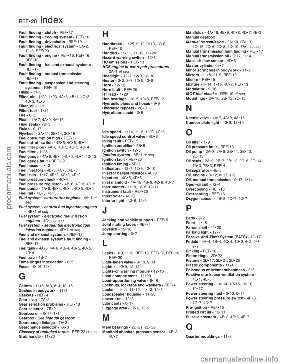
Fault finding - clutch - REF•17
Fault finding - cooling system - REF•16
Fault finding - driveshafts - REF•19
Fault finding - electrical system - 5A•2,
12 •3, REF •20
Fault finding - engine - REF•15, REF•16,
REF•18
Fault finding - fuel and exhaust systems -
REF•17
Fault finding - manual transmission - REF•17
Fault finding - suspension and steering
systems - REF•19
Filling - 11•3
Filter, air -1•22, 1•23, 4A•3, 4B•4, 4C•3,
4D•3, 4E•5
Filter, oil -1•9
Filter, fuel -1•25
Fire - 0•5
Float - 4A•7, 4A•9, 4A•16
Fluid seals - 7B•3
Fluids - 0•17
Flywheel - 2A•11, 2B•14, 2C•16
Fuel consumption high - REF•17
Fuel cut-off switch - 4B•5, 4C•5, 4D•4
Fuel filler pipe - 4A•6, 4B•5, 4C•5, 4D•4
Fuel filter - 1•25
Fuel gauge - 4A•6, 4B•4, 4C•5, 4D•4, 12 •12
Fuel gauge fault - REF•20
Fuel hoses - 1•13
Fuel injectors - 4B•5, 4C•5, 4D•5
Fuel lines - 1•17, 4B•3, 4C•3, 4D•2
Fuel pressure check - 4C•4
Fuel pressure regulator - 4B•6, 4C•6, 4D•5
Fuel pump - 4A•5, 4B•4, 4C•4, 4C•5, 4D•4
Fuel rail - 4C•5, 4D•5
Fuel system - carburettor engines -4A•1 et
seq
Fuel system - central fuel injection engines
-4B•1 et seq
Fuel system - electronic fuel injection engines -4C•1 et seq
Fuel system - sequential electronic fuel
injection engines -4D•1 et seq
Fuel and exhaust systems - REF•13
Fuel and exhaust systems fault finding - REF•17
Fuel tank - 4A•5, 4A•6, 4B•4, 4B•5, 4C•5,
4D•4
Fuel trap - 4B•7
Fume or gas intoxication - 0•5
Fuses - 0•16, 12 •4
G
Gaiters - 1•16, 8•3, 8•4, 10 •15
Gashes in bodywork - 11•3
Gaskets - REF •4
Gear lever - 7A•2
Gear selection problems - REF•18
Gear selector - 7B•2
Gearbox oil - 0•17, 1•14
Gearbox - See Manual gearbox
Gearchange linkage - 7A•2
Gearchange selector - 7A•3
Glossary of technical terms - REF•22 et seq
Grab handle - 11•20
H
Handbrake - 1•25, 9•12, 9•13, 12 •6,
REF•10
Handles - 11•11, 11•13, 11 •20
Hazard warning switch - 12•8
HC emissions - REF•13
HCS engine in-car repair procedures -
2A•1 et seq
Headlight - 12•7, 12 •9, 12 •10
Heater - 3•2, 3•8, 12 •6, 12•9
Horn - 12•12
Horn fault - REF•20
HT lead - 1•20
Hub bearings - 10•5, 10•8, REF •12
Hydraulic pipes and hoses - 9•9
Hydraulic tappets - 2C•8
Hydrofluoric acid - 0•5
I
Idle speed -1•14, 1•15, 1•20, 4C•6
Idle speed control valve - 4D•6
Idling fault - REF•15
Ignition amplifier - 5B•5
Ignition switch - 12•5
Ignition system -5B•1 et seq
Ignition fault - REF•20
Ignition timing - 5B•7
Indicators - 12•7, 12•9, 12 •10
Injector ballast resistor - 4B•9
Injectors - 4C•5, 4D•5
Inlet manifold - 4A•18, 4B•9, 4C•8, 4D•7
Instruments - 1•18, 12•8, 12•11
Instrument fault - REF•20
Intercooler - 4C•8
Interior light - 12•6, 12 •9
J
Jacking and vehicle support - REF•5
Joint mating faces - REF•4
Joystick - 12•16
Jump starting - 0•7
L
Leaks -0•9, 1•12, REF •16, REF•17, REF•18,
REF•20
Light-laden valve - 9•13, 9•14
Lighter - 12•9, 12 •12
Lights-on warning module - 12•16
Load compartment - 11•20
Load-apportioning valve - 9•16
Locknuts ,locktabs and washers - REF•4
Locks - 11•11, 11•12, 11•13, 12 •5
Loudspeaker housing - 11•20
Lower arm - 10•8
Lubricants - 0•17
Luggage area - 12•6, 12•9
M
Main bearings - 2D•21, 2D•22
Manifold absolute pressure sensor - 4B•8,
4C•7 Manifolds -
4A•18, 4B•9, 4C•8, 4D•7, 4E•3
Manual gearbox
Manual transmission -2A•10, 2B•13,
2C•15, 2D•6, 2D•8, 2D•10, 7A•1 et seq
Manual transmission fault finding - REF•17
Manual transmission oil - 0•17, 1•14
Mass air flow sensor - 4D•6
Master cylinder - 9•7
Minor scratches in bodywork - 11•2
Mirrors - 11 •8, 11•9, REF •10
Misfire - REF•15
Mixture - 1•14, 1•15, 4C•7, REF•13
Modulator - 9•16
MOT test checks - REF•10et seq
Mountings - 2A•10, 2B•13, 2C•15
N
Needle valve - 4A•7, 4A•9, 4A•16
Number plate light - 12•8, 12 •10
O
Oil filter - 1•9
Oil pressure fault - REF•16
Oil pump - 2A•8, 2A•9, 2B•11, 2B•12,
2C•13
Oil seals - 2A•9, 2B•7, 2B•12, 2C•8, 2C•14,
7A•3, 7B•3, REF •4
Oil separator - 4E•5
Oil, engine - 0•12, 0•17, 1•9
Oil, manual transmission - 0•17, 1•14
Open-circuit - 12•4
Overcooling - REF•16
Overheating - REF•16
Oxygen sensor - 4B•8, 4C•7, 4D•7
P
Pads -9•2
Paint - 1•18
Parcel shelf - 11•20
Parking light - 12•7
Passive Anti-Theft System (PATS) - 12•17
Pedals - 4A•4, 4B•4, 4C•4, 4D•3, 6•2, 9•8,
9•9
Pinking - REF•16
Piston rings - 2D•22
Pistons - 2D•17, 2D•24, 2D•25
Plastic components - 11•4
Poisonous or irritant substances - 0•5
Positive crankcase ventilation system - 4E•1, 4E•5
Power steering - 10•14, 10•15, 10•16,
10 •17
Power steering fluid - 0•13, 0•17
Power steering pressure switch - 4B•8,
4C•7, 4D•7
Pre-ignition - REF•16
Printed circuit - 12•11
Pulse-air system - 4E•2, 4E•6, 4E•7
Q
Quarter mouldings - 11•8
REF•28Index
1595 Ford Fiesta Remakeprocarmanuals.com
http://vnx.su