1989 FORD FIESTA headlights
[x] Cancel search: headlightsPage 149 of 296
25Refitting is the reverse of the removal
procedure, noting the following points: a) Renew the regulator sealing O-ring
whenever the regulator is disturbed.
Lubricate the new O-ring with clean
engine oil on installation.
b) Locate the regulator carefully in the fuel
rail recess, and tighten the bolts securely.
c) On completion, switch the ignition on and off five times, to activate the fuel pump
and pressurise the system, without
cranking the engine. Check for signs of
fuel leaks around all disturbed unions and
joints before attempting to start the
engine.
Idle speed control valve
26 Disconnect the battery negative (earth)
lead (refer to Chapter 5A, Section 1).
27 Disconnect the valve’s wiring multi-plug
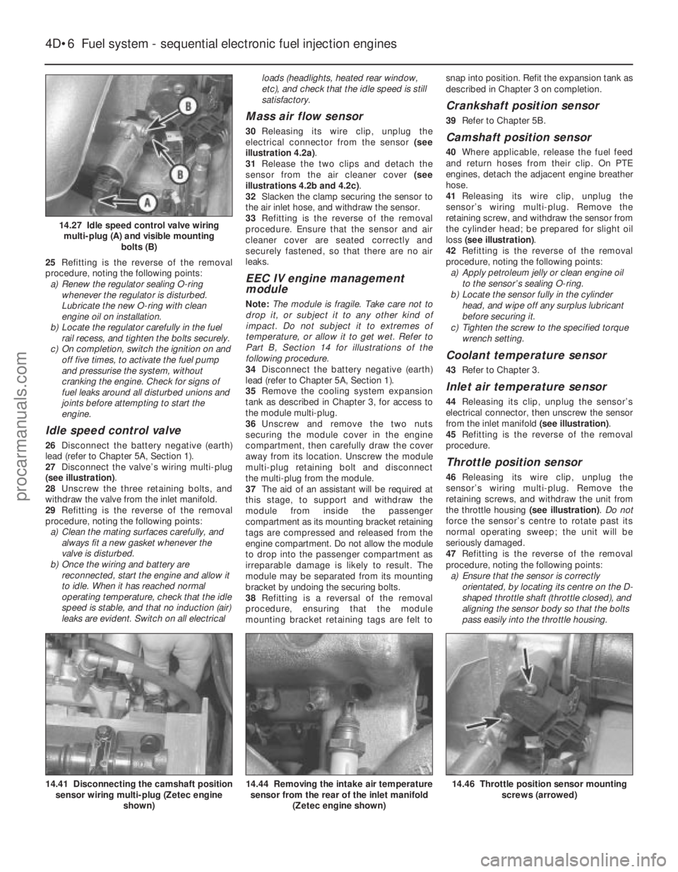
(see illustration) .
28 Unscrew the three retaining bolts, and
withdraw the valve from the inlet manifold.
29 Refitting is the reverse of the removal
procedure, noting the following points: a) Clean the mating surfaces carefully, and
always fit a new gasket whenever the
valve is disturbed.
b) Once the wiring and battery are
reconnected, start the engine and allow it
to idle. When it has reached normal
operating temperature, check that the idle
speed is stable, and that no induction (air)
leaks are evident. Switch on all electrical loads (headlights, heated rear window,
etc), and check that the idle speed is still
satisfactory.
Mass air flow sensor
30
Releasing its wire clip, unplug the
electrical connector from the sensor (see
illustration 4.2a) .
31 Release the two clips and detach the
sensor from the air cleaner cover (see
illustrations 4.2b and 4.2c) .
32 Slacken the clamp securing the sensor to
the air inlet hose, and withdraw the sensor.
33 Refitting is the reverse of the removal
procedure. Ensure that the sensor and air
cleaner cover are seated correctly and
securely fastened, so that there are no air
leaks.
EEC IV engine management
module
Note: The module is fragile. Take care not to
drop it, or subject it to any other kind of
impact. Do not subject it to extremes of
temperature, or allow it to get wet. Refer to
Part B, Section 14 for illustrations of the
following procedure.
34 Disconnect the battery negative (earth)
lead (refer to Chapter 5A, Section 1).
35 Remove the cooling system expansion
tank as described in Chapter 3, for access to
the module multi-plug.
36 Unscrew and remove the two nuts
securing the module cover in the engine
compartment, then carefully draw the cover
away from its location. Unscrew the module
multi-plug retaining bolt and disconnect
the multi-plug from the module.
37 The aid of an assistant will be required at
this stage, to support and withdraw the
module from inside the passenger
compartment as its mounting bracket retaining
tags are compressed and released from the
engine compartment. Do not allow the module
to drop into the passenger compartment as
irreparable damage is likely to result. The
module may be separated from its mounting
bracket by undoing the securing bolts.
38 Refitting is a reversal of the removal
procedure, ensuring that the module
mounting bracket retaining tags are felt to snap into position. Refit the expansion tank as
described in Chapter 3 on completion.
Crankshaft position sensor
39
Refer to Chapter 5B.
Camshaft position sensor
40Where applicable, release the fuel feed
and return hoses from their clip. On PTE
engines, detach the adjacent engine breather
hose.
41 Releasing its wire clip, unplug the
sensor’s wiring multi-plug. Remove the
retaining screw, and withdraw the sensor from
the cylinder head; be prepared for slight oil
loss (see illustration) .
42 Refitting is the reverse of the removal
procedure, noting the following points: a) Apply petroleum jelly or clean engine oil
to the sensor’s sealing O-ring.
b) Locate the sensor fully in the cylinder
head, and wipe off any surplus lubricant
before securing it.
c) Tighten the screw to the specified torque wrench setting.
Coolant temperature sensor
43 Refer to Chapter 3.
Inlet air temperature sensor
44Releasing its clip, unplug the sensor’s
electrical connector, then unscrew the sensor
from the inlet manifold (see illustration).
45 Refitting is the reverse of the removal
procedure.
Throttle position sensor
46 Releasing its wire clip, unplug the
sensor’s wiring multi-plug. Remove the
retaining screws, and withdraw the unit from
the throttle housing (see illustration). Do not
force the sensor’s centre to rotate past its
normal operating sweep; the unit will be
seriously damaged.
47 Refitting is the reverse of the removal
procedure, noting the following points: a) Ensure that the sensor is correctly orientated, by locating its centre on the D-
shaped throttle shaft (throttle closed), and
aligning the sensor body so that the bolts
pass easily into the throttle housing.
4D•6 Fuel system - sequential electronic fuel injection engines
14.46 Throttle position sensor mounting screws (arrowed)14.44 Removing the intake air temperaturesensor from the rear of the inlet manifold
(Zetec engine shown)14.41 Disconnecting the camshaft positionsensor wiring multi-plug (Zetec engine
shown)
14.27 Idle speed control valve wiringmulti-plug (A) and visible mounting bolts (B)
1595Ford Fiesta Remakeprocarmanuals.com
http://vnx.su
Page 162 of 296
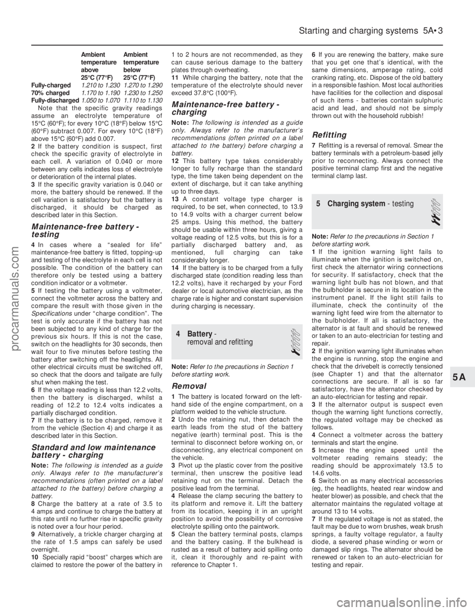
Ambient Ambient
temperature temperature
abovebelow
25°C (77°F) 25°C (77°F)
Fully-charged 1.210 to 1.230 1.270 to 1.290
70% charged 1.170 to 1.190 1.230 to 1.250
Fully-discharged 1.050 to 1.070 1.110 to 1.130
Note that the specific gravity readings
assume an electrolyte temperature of
15°C (60°F); for every 10°C (18°F) below 15°C
(60°F) subtract 0.007. For every 10°C (18°F)
above 15°C (60°F) add 0.007.
2 If the battery condition is suspect, first
check the specific gravity of electrolyte in
each cell. A variation of 0.040 or more
between any cells indicates loss of electrolyte
or deterioration of the internal plates.
3 If the specific gravity variation is 0.040 or
more, the battery should be renewed. If the
cell variation is satisfactory but the battery is
discharged, it should be charged as
described later in this Section.
Maintenance-free battery -
testing
4 In cases where a “sealed for life”
maintenance-free battery is fitted, topping-up
and testing of the electrolyte in each cell is not
possible. The condition of the battery can
therefore only be tested using a battery
condition indicator or a voltmeter.
5 If testing the battery using a voltmeter,
connect the voltmeter across the battery and
compare the result with those given in the
Specifications under “charge condition”. The
test is only accurate if the battery has not
been subjected to any kind of charge for the
previous six hours. If this is not the case,
switch on the headlights for 30 seconds, then
wait four to five minutes before testing the
battery after switching off the headlights. All
other electrical circuits must be switched off,
so check that the doors and tailgate are fully
shut when making the test.
6 If the voltage reading is less than 12.2 volts,
then the battery is discharged, whilst a
reading of 12.2 to 12.4 volts indicates a
partially discharged condition.
7 If the battery is to be charged, remove it
from the vehicle (Section 4) and charge it as
described later in this Section.
Standard and low maintenance
battery - charging
Note: The following is intended as a guide
only. Always refer to the manufacturer’s
recommendations (often printed on a label
attached to the battery) before charging a
battery.
8 Charge the battery at a rate of 3.5 to
4 amps and continue to charge the battery at
this rate until no further rise in specific gravity
is noted over a four hour period.
9 Alternatively, a trickle charger charging at
the rate of 1.5 amps can safely be used
overnight.
10 Specially rapid “boost” charges which are
claimed to restore the power of the battery in 1 to 2 hours are not recommended, as they
can cause serious damage to the battery
plates through overheating.
11
While charging the battery, note that the
temperature of the electrolyte should never
exceed 37.8°C (100°F).
Maintenance-free battery -
charging
Note: The following is intended as a guide
only. Always refer to the manufacturer’s
recommendations (often printed on a label
attached to the battery) before charging a
battery.
12 This battery type takes considerably
longer to fully recharge than the standard
type, the time taken being dependent on the
extent of discharge, but it can take anything
up to three days.
13 A constant voltage type charger is
required, to be set, when connected, to 13.9
to 14.9 volts with a charger current below
25 amps. Using this method, the battery
should be usable within three hours, giving a
voltage reading of 12.5 volts, but this is for a
partially discharged battery and, as
mentioned, full charging can take
considerably longer.
14 If the battery is to be charged from a fully
discharged state (condition reading less than
12.2 volts), have it recharged by your Ford
dealer or local automotive electrician, as the
charge rate is higher and constant supervision
during charging is necessary.
4 Battery -
removal and refitting
1
Note: Refer to the precautions in Section 1
before starting work.
Removal
1 The battery is located forward on the left-
hand side of the engine compartment, on a
platform welded to the vehicle structure.
2 Undo the retaining nut, then detach the
earth leads from the stud of the battery
negative (earth) terminal post. This is the
terminal to disconnect before working on, or
disconnecting, any electrical component on
the vehicle.
3 Pivot up the plastic cover from the positive
terminal, then unscrew the positive lead
retaining nut on the terminal. Detach the
positive lead from the terminal.
4 Release the clamp securing the battery to
its platform and remove it. Lift the battery
from its location, keeping it in an upright
position to avoid the possibility of corrosive
electrolyte spilling onto the paintwork.
5 Clean the battery terminal posts, clamps
and the battery casing. If the bulkhead is
rusted as a result of battery acid spilling onto
it, clean it thoroughly and re-paint with
reference to Chapter 1. 6
If you are renewing the battery, make sure
that you get one that’s identical, with the
same dimensions, amperage rating, cold
cranking rating, etc. Dispose of the old battery
in a responsible fashion. Most local authorities
have facilities for the collection and disposal
of such items - batteries contain sulphuric
acid and lead, and should not be simply
thrown out with the household rubbish!
Refitting
7 Refitting is a reversal of removal. Smear the
battery terminals with a petroleum-based jelly
prior to reconnecting. Always connect the
positive terminal clamp first and the negative
terminal clamp last.
5 Charging system - testing
2
Note:Refer to the precautions in Section 1
before starting work.
1 If the ignition warning light fails to
illuminate when the ignition is switched on,
first check the alternator wiring connections
for security. If satisfactory, check that the
warning light bulb has not blown, and that
the bulbholder is secure in its location in the
instrument panel. If the light still fails to
illuminate, check the continuity of the
warning light feed wire from the alternator to
the bulbholder. If all is satisfactory, the
alternator is at fault and should be renewed
or taken to an auto-electrician for testing and
repair.
2 If the ignition warning light illuminates when
the engine is running, stop the engine and
check that the drivebelt is correctly tensioned
(see Chapter 1) and that the alternator
connections are secure. If all is so far
satisfactory, have the alternator checked by
an auto-electrician for testing and repair.
3 If the alternator output is suspect even
though the warning light functions correctly,
the regulated voltage may be checked as
follows.
4 Connect a voltmeter across the battery
terminals and start the engine.
5 Increase the engine speed until the
voltmeter reading remains steady; the
reading should be approximately 13.5 to
14.6 volts.
6 Switch on as many electrical accessories
(eg, the headlights, heated rear window and
heater blower) as possible, and check that the
alternator maintains the regulated voltage at
around 13 to 14 volts.
7 If the regulated voltage is not as stated, the
fault may be due to worn brushes, weak brush
springs, a faulty voltage regulator, a faulty
diode, a severed phase winding or worn or
damaged slip rings. The alternator should be
renewed or taken to an auto-electrician for
testing and repair.
Starting and charging systems 5A•3
5A
1595Ford Fiesta Remakeprocarmanuals.com
http://vnx.su
Page 165 of 296
14Remove the rotor from the rear housing
and the stator. If difficulty is experienced, heat
the rear housing with a 200-watt soldering
iron for three or four minutes.
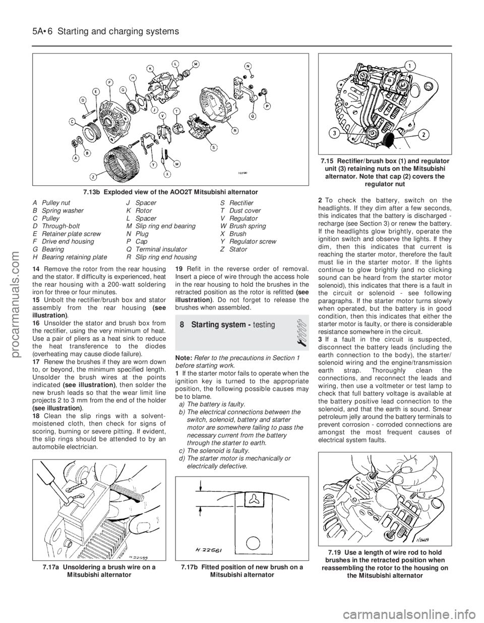
15 Unbolt the rectifier/brush box and stator
assembly from the rear housing (see
illustration) .
16 Unsolder the stator and brush box from
the rectifier, using the very minimum of heat.
Use a pair of pliers as a heat sink to reduce
the heat transference to the diodes
(overheating may cause diode failure).
17 Renew the brushes if they are worn down
to, or beyond, the minimum specified length.
Unsolder the brush wires at the points
indicated (see illustration) , then solder the
new brush leads so that the wear limit line
projects 2 to 3 mm from the end of the holder
(see illustration) .
18 Clean the slip rings with a solvent-
moistened cloth, then check for signs of
scoring, burning or severe pitting. If evident,
the slip rings should be attended to by an
automobile electrician. 19
Refit in the reverse order of removal.
Insert a piece of wire through the access hole
in the rear housing to hold the brushes in the
retracted position as the rotor is refitted (see
illustration) . Do not forget to release the
brushes when assembled.
8 Starting system - testing
1
Note:Refer to the precautions in Section 1
before starting work.
1 If the starter motor fails to operate when the
ignition key is turned to the appropriate
position, the following possible causes may
be to blame.
a) The battery is faulty.
b) The electrical connections between the
switch, solenoid, battery and starter
motor are somewhere failing to pass the
necessary current from the battery
through the starter to earth.
c) The solenoid is faulty.
d) The starter motor is mechanically or
electrically defective. 2
To check the battery, switch on the
headlights. If they dim after a few seconds,
this indicates that the battery is discharged -
recharge (see Section 3) or renew the battery.
If the headlights glow brightly, operate the
ignition switch and observe the lights. If they
dim, then this indicates that current is
reaching the starter motor, therefore the fault
must lie in the starter motor. If the lights
continue to glow brightly (and no clicking
sound can be heard from the starter motor
solenoid), this indicates that there is a fault in
the circuit or solenoid - see following
paragraphs. If the starter motor turns slowly
when operated, but the battery is in good
condition, then this indicates that either the
starter motor is faulty, or there is considerable
resistance somewhere in the circuit.
3 If a fault in the circuit is suspected,
disconnect the battery leads (including the
earth connection to the body), the starter/
solenoid wiring and the engine/transmission
earth strap. Thoroughly clean the
connections, and reconnect the leads and
wiring, then use a voltmeter or test lamp to
check that full battery voltage is available at
the battery positive lead connection to the
solenoid, and that the earth is sound. Smear
petroleum jelly around the battery terminals to
prevent corrosion - corroded connections are
amongst the most frequent causes of
electrical system faults.
5A•6 Starting and charging systems
7.19 Use a length of wire rod to hold
brushes in the retracted position when
reassembling the rotor to the housing on
the Mitsubishi alternator
7.17b Fitted position of new brush on a Mitsubishi alternator7.17a Unsoldering a brush wire on aMitsubishi alternator
7.15 Rectifier/brush box (1) and regulatorunit (3) retaining nuts on the Mitsubishialternator. Note that cap (2) covers the regulator nut
A Pulley nut
B Spring washer
C Pulley
D Through-bolt
E Retainer plate screw
F Drive end housing
G Bearing
H Bearing retaining plate J Spacer
K Rotor
L Spacer
M Slip ring end bearing
N Plug
P Cap
Q Terminal insulator
R Slip ring end housing S Rectifier
T Dust cover
V Regulator
W Brush spring
X Brush
Y Regulator screw
Z Stator
1595Ford Fiesta Remake
7.13b Exploded view of the AOO2T Mitsubishi alternatorprocarmanuals.com
http://vnx.su
Page 218 of 296
Refitting
12To refit, engage the wheelarch moulding
into the clamp, align the moulding studs with
their wheelarch locations, then position the
moulding onto the wheelarch. Refit the four
fixing nuts to secure the upper part of the
moulding, but do not fully tighten.
13 Refit the plastic stud, but do not fully
tighten.
14 Offer the sill extension moulding to its
location, centring it between the front and rear
wheelarches to check the rear wheelarch
moulding alignment. Adjust the alignment as
necessary.
15 With the rear wheelarch moulding
alignment correct, fully tighten the fixing nuts
and the plastic stud.
16 Insert the rivet to secure the forward end
of the moulding.
17 Refit the sill extension moulding, as
described in Section 12.
15 Wind deflector/radiator grille slat - removal and refitting
1
Removal
1The radiator grille slat is secured to the front
bumper by three clips. To remove it, simply
slide the clips rearwards to release them, then
withdraw the grille slat from its bumper
locating holes.
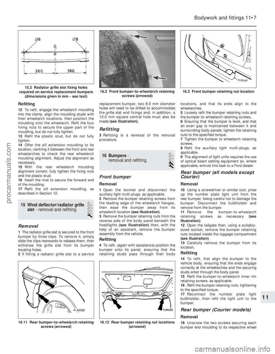
2 If fitting a radiator grille slat to a service replacement bumper, two 8.0 mm diameter
holes will need to be drilled to accommodate
the grille slat end fixings and, in addition, a
12.0 mm square central hole must also be
made
(see illustration) .
Refitting
3Refitting is a reversal of the removal
procedure.
16 Bumpers -
removal and refitting
2
Front bumper
Removal
1 Open the bonnet and disconnect the
auxiliary light multi-plugs, as applicable.
2 Remove the bumper retaining screws from
the leading edge of the wheelarch flanges,
then ease the bumper away from its
wheelarch location (see illustration).
3 Remove the bumper retaining nuts from the
reverse side of the body panel beneath the
headlights (see illustration) then, with the
help of an assistant, remove the bumper
assembly from the vehicle.
Refitting
4 To refit, (again with assistance) position the
bumper onto its panel, ensuring that the
retaining studs pass through their body locations, and that its ends align to the
wheelarches.
5
Loosely refit the bumper retaining nuts and
the bumper-to-wheelarch retaining screws.
6 Ensuring that the bumper is level, and that
an even gap is maintained between it and
surrounding body panels, tighten the retaining
nuts to the specified torque.
7 Tighten the bumper to wheelarch retaining
screws.
8 Refit the auxiliary light multi-plugs, as
applicable.
9 The alignment of light units requires the use
of optical beam setting equipment so, where
applicable, entrust this task to a Ford dealer.
Rear bumper (all models except
Courier)
Removal
10 Using a screwdriver or similar tool, prise
up the number plate light unit from the
rear bumper, being careful not to damage the
bumper. Disconnect the bulbholder and
remove from the bumper.
11 Remove the bumper-to-wheelarch
retaining screws as necessary (see
illustration) .
12 Open the tailgate then, using a suitably-
sized socket, remove the bumper retaining
nuts located inside the luggage compartment
(see illustration) .
13 Carefully remove the bumper from its
location.
Refitting
14 To refit, first align the bumper to the
vehicle body, ensuring that the ends engage
correctly at the wheelarches and the securing
studs enter through the body panel.
15 Refit the bumper-to-wheelarch inner rim
retaining screws, as applicable.
16 Refit the bumper retaining nuts, tightening
to the specified torque.
17 Reconnect the number plate light
bulbholder, then refit the light unit to the
bumper.
Rear bumper (Courier models)
Removal
18 Unscrew the two screws securing each
bumper end moulding to its respective wheel
Bodywork and fittings 11•7
16.2 Front bumper-to-wheelarch retaining screws (arrowed)15.2 Radiator grille slot fixing holes
required on service replacement bumpers (dimensions given in mm - see text)
16.12 Rear bumper retaining nut locations (arrowed)16.11 Rear bumper-to-wheelarch retainingscrews (arrowed)
16.3 Front bumper retaining nut location
11
1595Ford Fiesta Remakeprocarmanuals.com
http://vnx.su
Page 242 of 296
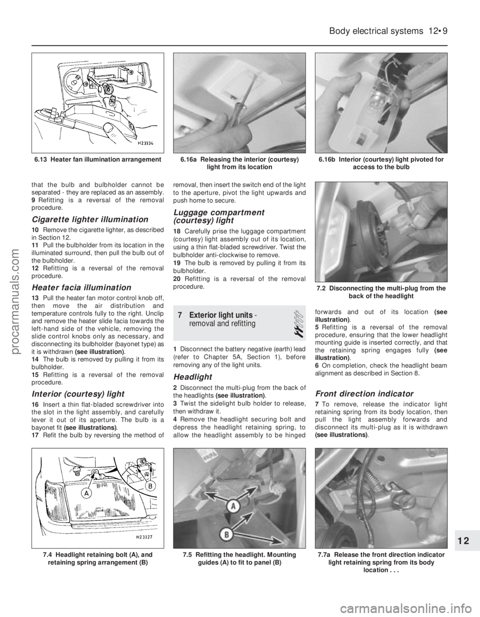
that the bulb and bulbholder cannot be
separated - they are replaced as an assembly.
9Refitting is a reversal of the removal
procedure.
Cigarette lighter illumination
10 Remove the cigarette lighter, as described
in Section 12.
11 Pull the bulbholder from its location in the
illuminated surround, then pull the bulb out of
the bulbholder.
12 Refitting is a reversal of the removal
procedure.
Heater facia illumination
13 Pull the heater fan motor control knob off,
then move the air distribution and
temperature controls fully to the right. Unclip
and remove the heater slide facia towards the
left-hand side of the vehicle, removing the
slide control knobs only as necessary, and
disconnecting its bulbholder (bayonet type) as
it is withdrawn (see illustration) .
14 The bulb is removed by pulling it from its
bulbholder.
15 Refitting is a reversal of the removal
procedure.
Interior (courtesy) light
16 Insert a thin flat-bladed screwdriver into
the slot in the light assembly, and carefully
lever it out of its aperture. The bulb is a
bayonet fit (see illustrations) .
17 Refit the bulb by reversing the method of removal, then insert the switch end of the light
to the aperture, pivot the light upwards and
push home to secure.
Luggage compartment
(courtesy) light
18
Carefully prise the luggage compartment
(courtesy) light assembly out of its location,
using a thin flat-bladed screwdriver. Twist the
bulbholder anti-clockwise to remove.
19 The bulb is removed by pulling it from its
bulbholder.
20 Refitting is a reversal of the removal
procedure.
7 Exterior light units -
removal and refitting
2
1 Disconnect the battery negative (earth) lead
(refer to Chapter 5A, Section 1), before
removing any of the light units.
Headlight
2 Disconnect the multi-plug from the back of
the headlights (see illustration) .
3 Twist the sidelight bulb holder to release,
then withdraw it.
4 Remove the headlight securing bolt and
depress the headlight retaining spring, to
allow the headlight assembly to be hinged forwards and out of its location
(see
illustration) .
5 Refitting is a reversal of the removal
procedure, ensuring that the lower headlight
mounting guide is inserted correctly, and that
the retaining spring engages fully (see
illustration) .
6 On completion, check the headlight beam
alignment as described in Section 8.Front direction indicator
7 To remove, release the indicator light
retaining spring from its body location, then
pull the light assembly forwards and
disconnect its multi-plug as it is withdrawn
(see illustrations) .
Body electrical systems 12•9
6.16b Interior (courtesy) light pivoted for
access to the bulb
7.2 Disconnecting the multi-plug from the
back of the headlight
6.16a Releasing the interior (courtesy)light from its location6.13 Heater fan illumination arrangement
7.7a Release the front direction indicatorlight retaining spring from its body
location . . .7.5 Refitting the headlight. Mountingguides (A) to fit to panel (B)7.4 Headlight retaining bolt (A), andretaining spring arrangement (B)
12
1595Ford Fiesta Remakeprocarmanuals.com
http://vnx.su
Page 277 of 296
1595 Ford Fiesta Remake
MOT test checksREF•11
REF
Seat belts and seats
Note: The following checks are applicable to
all seat belts, front and rear.
M Examine the webbing of all the belts
(including rear belts if fitted) for cuts, serious
fraying or deterioration. Fasten and unfasten
each belt to check the buckles. If applicable,
check the retracting mechanism. Check the
security of all seat belt mountings accessible
fr om inside the vehicle.
M The front seats themselves must be
secur ely attached and the backrests must
lock in the upright position.
Doors
M Both front doors must be able to be opened
and closed from outside and inside, and must
latch securely when closed.
V ehicle identification
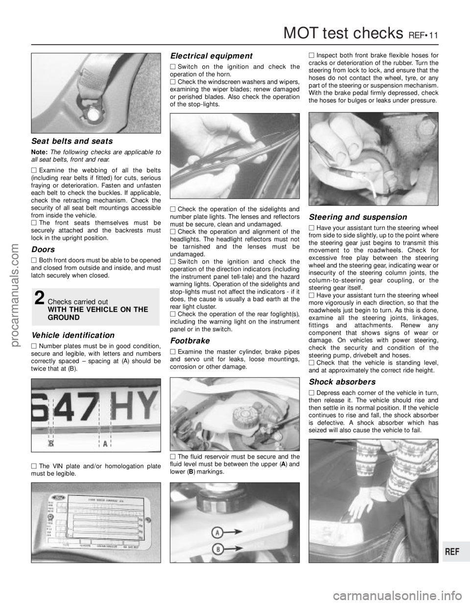
M Number plates must be in good condition,
secur e and legible, with letters and numbers
corr ectly spaced – spacing at (A) should be
twice that at (B).
M The VIN plate and/or homologation plate
must be legible.
Electrical equipment
M Switch on the ignition and check the
operation of the horn.
M Check the windscreen washers and wipers,
examining the wiper blades; renew damaged
or perished blades. Also check the operation
of the stop-lights.
M Check the operation of the sidelights and
number plate lights. The lenses and reflectors
must be secure, clean and undamaged.
M Check the operation and alignment of the
headlights. The headlight reflectors must not
be tarnished and the lenses must be
undamaged.
M Switch on the ignition and check the
operation of the direction indicators (including
the instrument panel tell-tale) and the hazard
war ning lights. Operation of the sidelights and
stop-lights must not affect the indicators - if it
does, the cause is usually a bad earth at the
r ear light cluster.
M Check the operation of the rear foglight(s),
including the warning light on the instrument
panel or in the switch.
Footbrake
M Examine the master cylinder, brake pipes
and servo unit for leaks, loose mountings,
corr osion or other damage.
M The fluid reservoir must be secure and the
fluid level must be between the upper ( A) and
lower ( B) markings. M
Inspect both front brake flexible hoses for
cracks or deterioration of the rubber . Turn the
steering from lock to lock, and ensure that the
hoses do not contact the wheel, tyre, or any
part of the steering or suspension mechanism.
With the brake pedal firmly depressed, check
the hoses for bulges or leaks under pressure.
Steering and suspension
M Have your assistant turn the steering wheel
fr om side to side slightly, up to the point where
the steering gear just begins to transmit this
movement to the roadwheels. Check for
excessive free play between the steering
wheel and the steering gear, indicating wear or
insecurity of the steering column joints, the
column-to-steering gear coupling, or the
steering gear itself.
M Have your assistant turn the steering wheel
mor e vigorously in each direction, so that the
r oadwheels just begin to turn. As this is done,
examine all the steering joints, linkages,
fittings and attachments. Renew any
component that shows signs of wear or
damage. On vehicles with power steering,
check the security and condition of the
steering pump, drivebelt and hoses.
M Check that the vehicle is standing level,
and at approximately the correct ride height.
Shock absorbers
M Depr ess each corner of the vehicle in turn,
then release it. The vehicle should rise and
then settle in its normal position. If the vehicle
continues to rise and fall, the shock absorber
is defective. A shock absorber which has
seized will also cause the vehicle to fail.
2Checks carried out
WITH THE VEHICLE ON THE
GROUND
procarmanuals.com
http://vnx.su