1989 FORD FIESTA clutch
[x] Cancel search: clutchPage 19 of 296
3Check that the roadwheel nuts are tightened
to the specified torque wrench setting.
4 Refit the wheel covers.
16 Door, tailgate and bonnet
check and lubrication
1
1Check that the doors and tailgate/boot lid
close securely. Check that the bonnet safety
catch operates correctly. Check the operation
of the door check straps.
2 Lubricate the hinges, door check straps,
the striker plates and the bonnet catch
sparingly with a little oil or grease.
17 Seat belt check
1
1 Check the seat belts for satisfactory
operation and condition. Inspect the webbing
for fraying and cuts. Check that they retract
smoothly and without binding into their reels.
2 Check that the seat belt mounting bolts are
tight, and if necessary tighten them to the
specified torque wrench settings as given in
Chapter 11.
18 Bodywork, paint and exterior trim check
1
1The best time to carry out this check is after
the car has been washed so that any surface
blemish or scratch will be clearly evident and
not hidden by a film of dirt.
2 Starting at one front corner check the
paintwork all around the car, looking for minor
scratches or more serious dents. Check all
the trim and make sure that it is securely
attached over its entire length.
3 Check the security of all door locks, door
mirrors, badges, bumpers, front grille and
wheel trim. Anything found loose, or in need of
further attention should be done with reference
to the relevant Chapters of this manual.
4 Rectify any problems noticed with the
paintwork or body panels as described in
Chapter 11.
19 Road test
1
Check the operation and
performance of the braking
system
1 Make sure that the vehicle does not pull to
one side when braking, and that the wheels
do not lock prematurely when braking hard.
2 Check that there is no vibration through the
steering when braking. 3
Check that the handbrake operates
correctly, without excessive movement of the
lever, and that it holds the vehicle stationary
on a slope.
4 Test the operation of the brake servo unit
as follows. With the engine switched off,
depress the footbrake four or five times to
exhaust the vacuum, then hold the pedal
depressed. Start the engine, and there should
be a noticeable “give” in the brake pedal as
vacuum builds up. Allow the engine to run for
at least two minutes, and then switch it off. If
the brake pedal is depressed again, it should
be possible to detect a hiss from the servo as
the pedal is depressed. After about four or five
applications, no further hissing should be
heard, and the pedal should feel considerably
firmer.
Steering and suspension
5 Check for any abnormalities in the steering,
suspension, handling or road “feel”.
6 Drive the vehicle, and check that there are
no unusual vibrations or noises.
7 Check that the steering feels positive, with
no excessive sloppiness or roughness, and
check for any suspension noises when
cornering and driving over bumps.
Drivetrain
8 Check the performance of the engine,
transmission and driveshafts.
9 Check that the engine starts correctly, both
when cold and when hot.
10 Listen for any unusual noises from the
engine and transmission.
11 Make sure that the engine runs smoothly
when idling, and that there is no hesitation
when accelerating.
12 On manual transmission models, check
that all gears can be engaged smoothly
without noise, and that the gear lever action is
not abnormally vague or “notchy”.
13 On automatic transmission models, make
sure that the drive seems smooth without
jerks or engine speed “flare-ups”. Check that
all the gear positions can be selected with the
vehicle at rest. If any problems are found, they
should be referred to a Ford dealer.
14 Listen for a metallic clicking sound from
the front of the vehicle, as the vehicle is driven
slowly in a circle with the steering on full-lock.
Carry out this check in both directions. If a
clicking noise is heard, this indicates wear in a
driveshaft joint, in which case renew the joint
if necessary.
Clutch
15 Check that the clutch pedal moves
smoothly and easily through its full travel, and
that the clutch itself functions correctly, with
no trace of slip or drag. If the movement is
uneven or stiff in places, check that the cable
is routed correctly, with no sharp turns.
16 Inspect both ends of the clutch inner
cable, both at the transmission end and inside
the car, for signs of wear and fraying.
Instruments and electrical
equipment
17 Check the operation of all instruments
and electrical equipment.
18 Make sure that all instruments read
correctly, and switch on all electrical equipment
in turn, to check that it functions properly.
20 Automatic transmission fluid level check
1
1The level of the automatic transmission fluid
should be carefully maintained. Low fluid level
can lead to slipping or loss of drive, while
overfilling can cause foaming, loss of fluid and
transmission damage.
2 The transmission fluid level should only be
checked when the transmission is hot (at its
normal operating temperature). If the vehicle
has just been driven over 10 miles (15 miles in
a cold climate), and the fluid temperature is 60
to 70ºC, the transmission is hot.
Caution: If the vehicle has just been driven
for a long time at high speed or in city
traffic in hot weather, or if it has been
pulling a trailer, an accurate fluid level
reading cannot be obtained. In these
circumstances, allow the fluid to cool
down for about 30 minutes.
3 Park the vehicle on level ground, apply the
handbrake, and start the engine. While the
engine is idling, depress the brake pedal and
move the selector lever through all the gear
positions three times, beginning and ending in
“P”.
4 Allow the engine to idle for one minute, then
(with the engine still idling) remove the
dipstick from its tube. Note the condition and
colour of the fluid on the dipstick.
5 Wipe the fluid from the dipstick with a clean
rag, and re-insert it into the filler tube until the
cap seats.
6 Pull the dipstick out again, and note the
fluid level. The level should be between
the “MIN” and “MAX” marks. If the level is
on the “MIN” mark, stop the engine, and add
the specified automatic transmission fluid
through the dipstick tube, using a clean funnel
if necessary. It is important not to introduce
dirt into the transmission when topping-up.
7 Add the fluid a little at a time, and keep
checking the level as previously described
until it is correct. The difference between the
“MIN” and “MAX” marks on the dipstick is
approximately 0.4 litres.
8 The need for regular topping-up of the
transmission fluid indicates a leak, which
should be found and rectified without delay.
9 The condition of the fluid should also be
checked along with the level. If the fluid on the
dipstick is black or a dark reddish-brown
colour, or if it has a burned smell, the fluid
should be changed. If you are in doubt about
the condition of the fluid, purchase some new
fluid, and compare the two for colour and smell.
1•18Every 10 000 miles or 12 months
1595Ford Fiesta Remakeprocarmanuals.com
http://vnx.su
Page 33 of 296
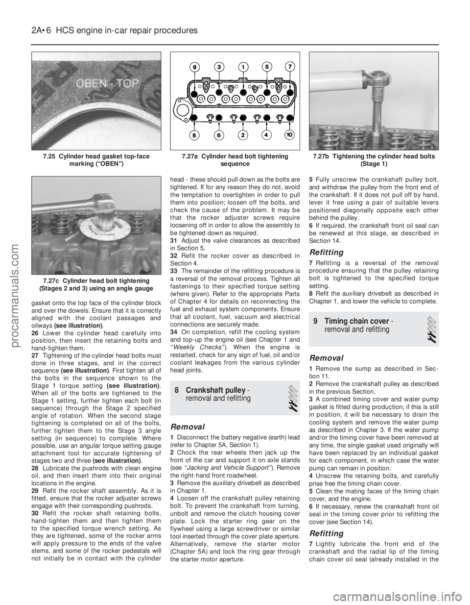
gasket onto the top face of the cylinder block
and over the dowels. Ensure that it is correctly
aligned with the coolant passages and
oilways (see illustration) .
26 Lower the cylinder head carefully into
position, then insert the retaining bolts and
hand-tighten them.
27 Tightening of the cylinder head bolts must
done in three stages, and in the correct
sequence (see illustration) . First tighten all of
the bolts in the sequence shown to the
Stage 1 torque setting (see illustration).
When all of the bolts are tightened to the
Stage 1 setting, further tighten each bolt (in
sequence) through the Stage 2 specified
angle of rotation. When the second stage
tightening is completed on all of the bolts,
further tighten them to the Stage 3 angle
setting (in sequence) to complete. Where
possible, use an angular torque setting gauge
attachment tool for accurate tightening of
stages two and three (see illustration).
28 Lubricate the pushrods with clean engine
oil, and then insert them into their original
locations in the engine.
29 Refit the rocker shaft assembly. As it is
fitted, ensure that the rocker adjuster screws
engage with their corresponding pushrods.
30 Refit the rocker shaft retaining bolts,
hand-tighten them and then tighten them
to the specified torque wrench setting. As
they are tightened, some of the rocker arms
will apply pressure to the ends of the valve
stems, and some of the rocker pedestals will
not initially be in contact with the cylinder head - these should pull down as the bolts are
tightened. If for any reason they do not, avoid
the temptation to overtighten in order to pull
them into position; loosen off the bolts, and
check the cause of the problem. It may be
that the rocker adjuster screws require
loosening off in order to allow the assembly to
be tightened down as required.
31
Adjust the valve clearances as described
in Section 5.
32 Refit the rocker cover as described in
Section 4.
33 The remainder of the refitting procedure is
a reversal of the removal process. Tighten all
fastenings to their specified torque setting
(where given). Refer to the appropriate Parts
of Chapter 4 for details on reconnecting the
fuel and exhaust system components. Ensure
that all coolant, fuel, vacuum and electrical
connections are securely made.
34 On completion, refill the cooling system
and top-up the engine oil (see Chapter 1 and
“Weekly Checks” ). When the engine is
restarted, check for any sign of fuel, oil and/or
coolant leakages from the various cylinder
head joints.
8 Crankshaft pulley -
removal and refitting
2
Removal
1 Disconnect the battery negative (earth) lead
(refer to Chapter 5A, Section 1).
2 Chock the rear wheels then jack up the
front of the car and support it on axle stands
(see “Jacking and Vehicle Support” ). Remove
the right-hand front roadwheel.
3 Remove the auxiliary drivebelt as described
in Chapter 1.
4 Loosen off the crankshaft pulley retaining
bolt. To prevent the crankshaft from turning,
unbolt and remove the clutch housing cover
plate. Lock the starter ring gear on the
flywheel using a large screwdriver or similar
tool inserted through the cover plate aperture.
Alternatively, remove the starter motor
(Chapter 5A) and lock the ring gear through
the starter motor aperture. 5
Fully unscrew the crankshaft pulley bolt,
and withdraw the pulley from the front end of
the crankshaft. If it does not pull off by hand,
lever it free using a pair of suitable levers
positioned diagonally opposite each other
behind the pulley.
6 If required, the crankshaft front oil seal can
be renewed at this stage, as described in
Section 14.
Refitting
7 Refitting is a reversal of the removal
procedure ensuring that the pulley retaining
bolt is tightened to the specified torque
setting.
8 Refit the auxiliary drivebelt as described in
Chapter 1, and lower the vehicle to complete.
9 Timing chain cover -
removal and refitting
2
Removal
1 Remove the sump as described in Sec-
tion 11.
2 Remove the crankshaft pulley as described
in the previous Section.
3 A combined timing cover and water pump
gasket is fitted during production; if this is still
in position, it will be necessary to drain the
cooling system and remove the water pump
as described in Chapter 3. If the water pump
and/or the timing cover have been removed at
any time, the single gasket used originally will
have been replaced by an individual gasket
for each component, in which case the water
pump can remain in position.
4 Unscrew the retaining bolts, and carefully
prise free the timing chain cover.
5 Clean the mating faces of the timing chain
cover, and the engine.
6 If necessary, renew the crankshaft front oil
seal in the timing cover prior to refitting the
cover (see Section 14).
Refitting
7 Lightly lubricate the front end of the
crankshaft and the radial lip of the timing
chain cover oil seal (already installed in the
2A•6 HCS engine in-car repair procedures
7.27c Cylinder head bolt tightening
(Stages 2 and 3) using an angle gauge
7.27b Tightening the cylinder head bolts (Stage 1)7.27a Cylinder head bolt tighteningsequence7.25 Cylinder head gasket top-facemarking (“OBEN”)
1595Ford Fiesta Remakeprocarmanuals.com
http://vnx.su
Page 34 of 296
cover). Using a new gasket, fit the timing
chain cover, centring it with the aid of the
crankshaft pulley - lubricate the seal contact
surfaces beforehand. Refit and tighten the
retaining bolts but, where applicable, leave
out the timing cover bolt which also secures
the water pump at this stage.
8Where applicable, refit the water pump as
described in Chapter 3.
9 Refit the crankshaft pulley as described in
the previous Section.
10 Refit the sump as described in Section 11.
10Timing chain, sprockets and
tensioner - removal,
inspection and refitting
3
Removal
1 Remove the timing chain cover as
described in the previous Section.
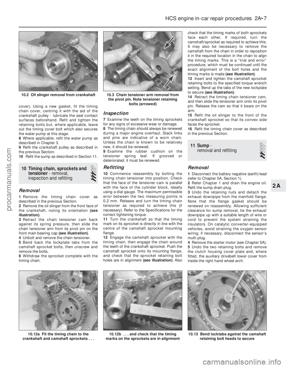
2 Remove the oil slinger from the front face of
the crankshaft, noting its orientation (see
illustration) .
3 Retract the chain tensioner cam back
against its spring pressure, then slide the
chain tensioner arm from its pivot pin on the
front main bearing cap (see illustration).
4 Unbolt and remove the chain tensioner.
5 Bend back the lockplate tabs from the
camshaft sprocket bolts, then unscrew and
remove the bolts.
6 Withdraw the sprocket complete with the
timing chain.
Inspection
7 Examine the teeth on the timing sprockets
for any signs of excessive wear or damage.
8 The timing chain should always be renewed
during a major engine overhaul. Slack links
and pins are indicative of a worn chain.
Unless the chain is known to be relatively
new, it should be renewed.
9 Examine the rubber cushion on the
tensioner spring leaf. If grooved or
deteriorated, it must be renewed.
Refitting
10 Commence reassembly by bolting the
timing chain tensioner into position. Check
that the face of the tensioner cam is parallel
with the face of the cylinder block, ideally
using a dial gauge. The maximum permissible
error between the two measuring points is
0.2 mm. Release and turn the timing chain
tensioner as required to achieve this (if
necessary). Refer to the Specifications for the
correct tightening torque.
11 Turn the crankshaft so that the timing
mark on its sprocket is directly in line with the
centre of the camshaft sprocket mounting
flange.
12 Engage the camshaft sprocket with the
timing chain, then engage the chain around
the teeth of the crankshaft sprocket. Push the
camshaft sprocket onto its mounting flange,
and check that the sprocket retaining bolt
holes are in alignment (see illustration). Alsocheck that the timing marks of both sprockets
face each other. If required, turn the
camshaft/sprocket as required to achieve this.
It may also be necessary to remove the
camshaft from the chain in order to reposition
it in the required location in the chain to align
the timing marks. This is a “trial and error”
procedure, which must be continued until the
exact alignment of the bolt holes and the
timing marks is made
(see illustration).
13 Insert and tighten the camshaft sprocket
retaining bolts to the specified torque wrench
setting. Bend up the tabs of the new lockplate
to secure (see illustration) .
14 Retract the timing chain tensioner cam,
and then slide the tensioner arm onto its pivot
pin. Release the cam so that it bears on the
arm.
15 Refit the oil slinger to the front of the
crankshaft sprocket so that its convex side
faces the sprocket.
16 Refit the timing chain cover as described
in the previous Section.
11 Sump -
removal and refitting
2
Removal
1 Disconnect the battery negative (earth) lead
(refer to Chapter 5A, Section 1).
2 Refer Chapter 1 and drain the engine oil.
Refit the sump drain plug.
3 Undo the retaining nuts and detach the
exhaust downpipe from the manifold flange.
Note that the flange gasket should be
renewed on reassembly. Allowing sufficient
clearance for sump removal, tie the exhaust
downpipe up with a suitable length of wire or
cord to prevent the system straining the
insulators. On catalytic converter-equipped
vehicles, avoid straining the oxygen sensor
wiring; if necessary, disconnect the sensor’s
multi-plug.
4 Remove the starter motor (see Chapter 5A).
5 Undo the two retaining bolts and remove
the clutch housing cover plate and, where
fitted, the auxiliary drivebelt lower cover from
inside the right-hand wheel arch.
HCS engine in-car repair procedures 2A•7
10.12a Fit the timing chain to the
crankshaft and camshaft sprockets . . .
10.3 Chain tensioner arm removal from the pivot pin. Note tensioner retaining bolts (arrowed)10.2 Oil slinger removal from crankshaft
10.13 Bend locktabs against the camshaftretaining bolt heads to secure10.12b . . . and check that the timing
marks on the sprockets are in alignment
2A
1595Ford Fiesta Remakeprocarmanuals.com
http://vnx.su
Page 35 of 296
6Undo the eighteen bolts securing the sump
to the base of the engine crankcase, then
prise free and lower the sump. If the sump is
stuck tight to the engine, cut around the
flange gasket with a sharp knife, then lightly
tap and prise it free. Keep the sump upright as
it is lowered, to prevent spillage of any
remaining oil in it. Also be prepared for oil
drips from the crankcase when the sump is
removed.
7 Remove any dirt and old gasket from the
contact faces of the sump and crankcase, and
wash the sump out thoroughly before refitting.
Check that the mating faces of the sump are
not distorted. Check that the oil pick-up
strainer is clear, cleaning it if necessary.
Refitting
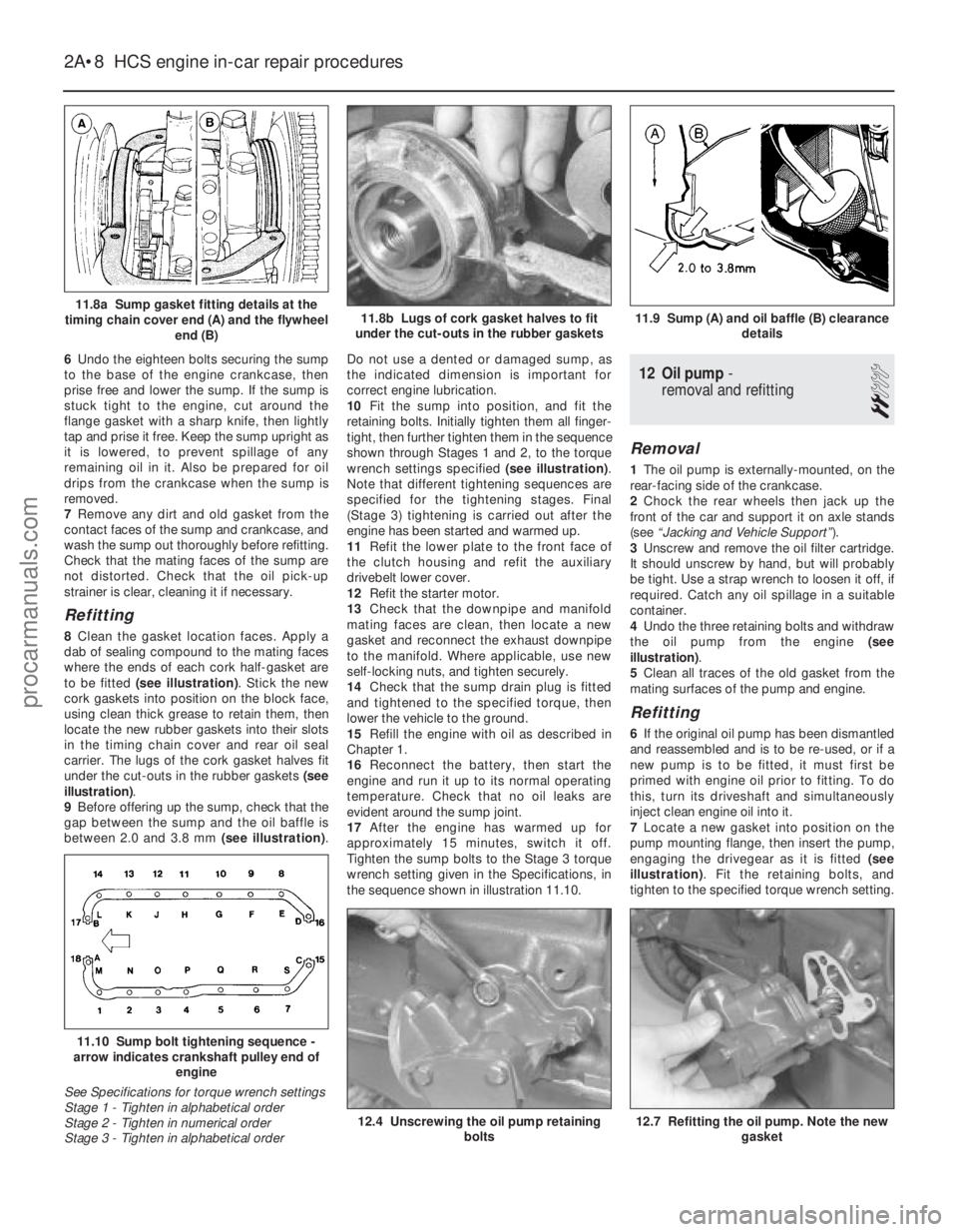
8 Clean the gasket location faces. Apply a
dab of sealing compound to the mating faces
where the ends of each cork half-gasket are
to be fitted (see illustration) . Stick the new
cork gaskets into position on the block face,
using clean thick grease to retain them, then
locate the new rubber gaskets into their slots
in the timing chain cover and rear oil seal
carrier. The lugs of the cork gasket halves fit
under the cut-outs in the rubber gaskets (see
illustration) .
9 Before offering up the sump, check that the
gap between the sump and the oil baffle is
between 2.0 and 3.8 mm (see illustration).Do not use a dented or damaged sump, as
the indicated dimension is important for
correct engine lubrication.
10
Fit the sump into position, and fit the
retaining bolts. Initially tighten them all finger-
tight, then further tighten them in the sequence
shown through Stages 1 and 2, to the torque
wrench settings specified (see illustration).
Note that different tightening sequences are
specified for the tightening stages. Final
(Stage 3) tightening is carried out after the
engine has been started and warmed up.
11 Refit the lower plate to the front face of
the clutch housing and refit the auxiliary
drivebelt lower cover.
12 Refit the starter motor.
13 Check that the downpipe and manifold
mating faces are clean, then locate a new
gasket and reconnect the exhaust downpipe
to the manifold. Where applicable, use new
self-locking nuts, and tighten securely.
14 Check that the sump drain plug is fitted
and tightened to the specified torque, then
lower the vehicle to the ground.
15 Refill the engine with oil as described in
Chapter 1.
16 Reconnect the battery, then start the
engine and run it up to its normal operating
temperature. Check that no oil leaks are
evident around the sump joint.
17 After the engine has warmed up for
approximately 15 minutes, switch it off.
Tighten the sump bolts to the Stage 3 torque
wrench setting given in the Specifications, in
the sequence shown in illustration 11.10.
12 Oil pump -
removal and refitting
2
Removal
1 The oil pump is externally-mounted, on the
rear-facing side of the crankcase.
2 Chock the rear wheels then jack up the
front of the car and support it on axle stands
(see “Jacking and Vehicle Support” ).
3 Unscrew and remove the oil filter cartridge.
It should unscrew by hand, but will probably
be tight. Use a strap wrench to loosen it off, if
required. Catch any oil spillage in a suitable
container.
4 Undo the three retaining bolts and withdraw
the oil pump from the engine (see
illustration) .
5 Clean all traces of the old gasket from the
mating surfaces of the pump and engine.
Refitting
6 If the original oil pump has been dismantled
and reassembled and is to be re-used, or if a
new pump is to be fitted, it must first be
primed with engine oil prior to fitting. To do
this, turn its driveshaft and simultaneously
inject clean engine oil into it.
7 Locate a new gasket into position on the
pump mounting flange, then insert the pump,
engaging the drivegear as it is fitted (see
illustration) . Fit the retaining bolts, and
tighten to the specified torque wrench setting.
2A•8 HCS engine in-car repair procedures
12.7 Refitting the oil pump. Note the new gasket12.4 Unscrewing the oil pump retaining bolts
11.10 Sump bolt tightening sequence -
arrow indicates crankshaft pulley end of
engine
See Specifications for torque wrench settings
Stage 1 - Tighten in alphabetical order
Stage 2 - Tighten in numerical order
Stage 3 - Tighten in alphabetical order
11.9 Sump (A) and oil baffle (B) clearance details11.8b Lugs of cork gasket halves to fit
under the cut-outs in the rubber gaskets11.8a Sump gasket fitting details at the
timing chain cover end (A) and the flywheel end (B)
1595Ford Fiesta Remakeprocarmanuals.com
http://vnx.su
Page 38 of 296
rear, and lower the transmission bearer from
the vehicle. Note plate fitment, as applicable,
for reassembly.
14Unscrew the single nut securing each
mounting and its retainer to the transmission
support bracket, and remove. The
transmission support brackets are fixed
externally to the transmission casing and do
not need to be removed for this operation.
All mountings
15 Refitting of all mountings is a reversal of
removal. Make sure that the original sequence
of assembly of washers and plates is
maintained.
16 Do not fully tighten any mounting bolts
until they are all located. As the mounting
bolts and nuts are tightened, check that the
mounting rubbers do not twist.
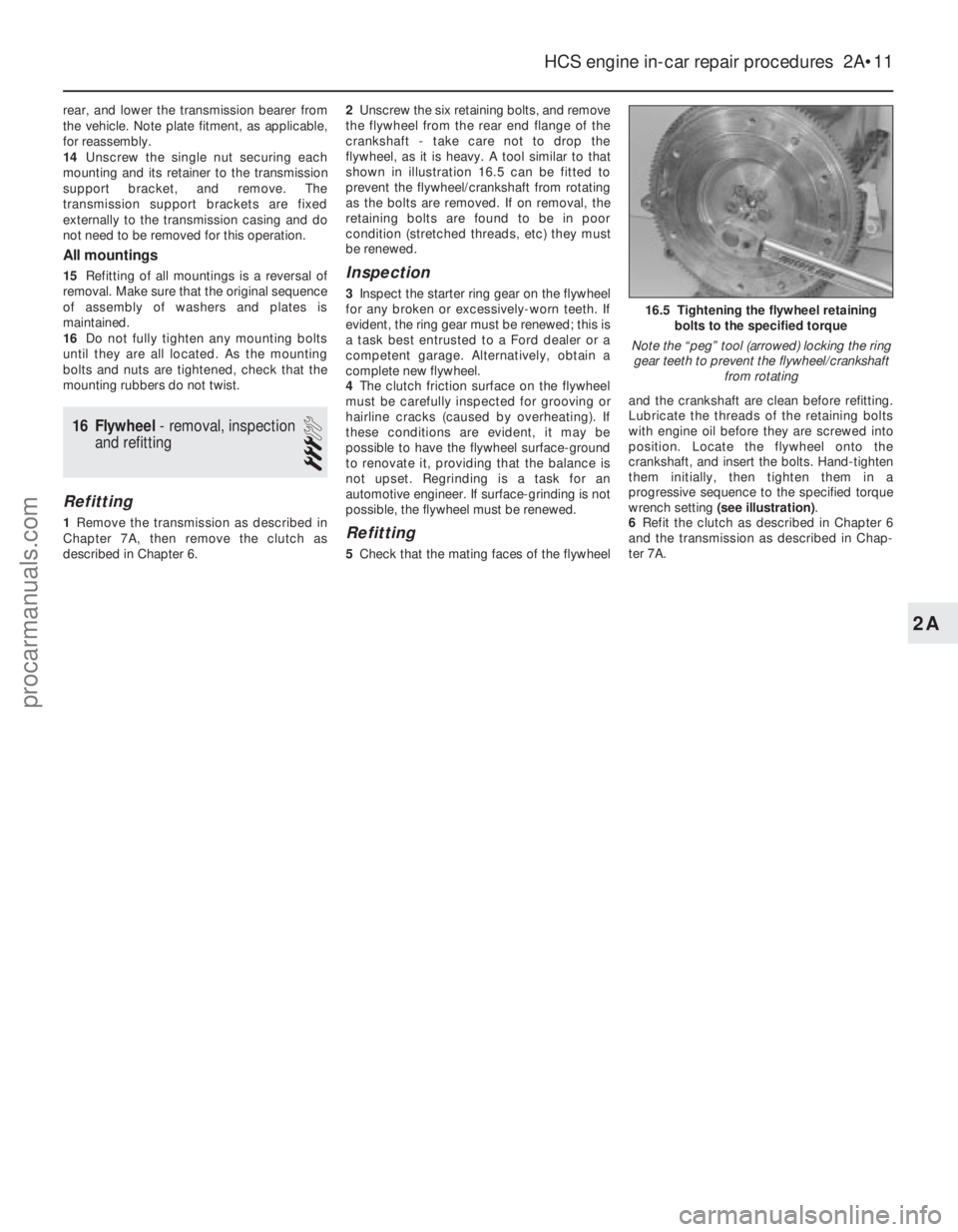
16 Flywheel - removal, inspection
and refitting
3
Refitting
1 Remove the transmission as described in
Chapter 7A, then remove the clutch as
described in Chapter 6. 2
Unscrew the six retaining bolts, and remove
the flywheel from the rear end flange of the
crankshaft - take care not to drop the
flywheel, as it is heavy. A tool similar to that
shown in illustration 16.5 can be fitted to
prevent the flywheel/crankshaft from rotating
as the bolts are removed. If on removal, the
retaining bolts are found to be in poor
condition (stretched threads, etc) they must
be renewed.
Inspection
3 Inspect the starter ring gear on the flywheel
for any broken or excessively-worn teeth. If
evident, the ring gear must be renewed; this is
a task best entrusted to a Ford dealer or a
competent garage. Alternatively, obtain a
complete new flywheel.
4 The clutch friction surface on the flywheel
must be carefully inspected for grooving or
hairline cracks (caused by overheating). If
these conditions are evident, it may be
possible to have the flywheel surface-ground
to renovate it, providing that the balance is
not upset. Regrinding is a task for an
automotive engineer. If surface-grinding is not
possible, the flywheel must be renewed.
Refitting
5 Check that the mating faces of the flywheel and the crankshaft are clean before refitting.
Lubricate the threads of the retaining bolts
with engine oil before they are screwed into
position. Locate the flywheel onto the
crankshaft, and insert the bolts. Hand-tighten
them initially, then tighten them in a
progressive sequence to the specified torque
wrench setting
(see illustration) .
6 Refit the clutch as described in Chapter 6
and the transmission as described in Chap-
ter 7A.
HCS engine in-car repair procedures 2A•11
16.5 Tightening the flywheel retaining bolts to the specified torque
Note the “peg” tool (arrowed) locking the ring gear teeth to prevent the flywheel/crankshaft from rotating
2A
1595Ford Fiesta Remakeprocarmanuals.com
http://vnx.su
Page 50 of 296
bolt(s) securing the gearchange mechanism
stabiliser bar/exhaust forward mounting
bracket (where fitted) and ease it out of the
way.
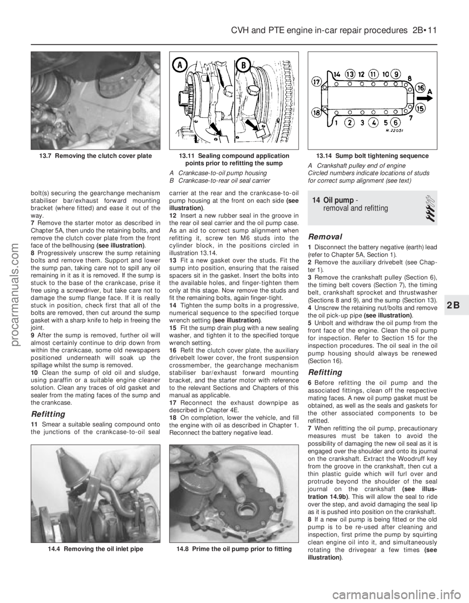
7Remove the starter motor as described in
Chapter 5A, then undo the retaining bolts, and
remove the clutch cover plate from the front
face of the bellhousing (see illustration).
8 Progressively unscrew the sump retaining
bolts and remove them. Support and lower
the sump pan, taking care not to spill any oil
remaining in it as it is removed. If the sump is
stuck to the base of the crankcase, prise it
free using a screwdriver, but take care not to
damage the sump flange face. If it is really
stuck in position, check first that all of the
bolts are removed, then cut around the sump
gasket with a sharp knife to help in freeing the
joint.
9 After the sump is removed, further oil will
almost certainly continue to drip down from
within the crankcase, some old newspapers
positioned underneath will soak up the
spillage whilst the sump is removed.
10 Clean the sump of old oil and sludge,
using paraffin or a suitable engine cleaner
solution. Clean any traces of old gasket and
sealer from the mating faces of the sump and
the crankcase.
Refitting
11 Smear a suitable sealing compound onto
the junctions of the crankcase-to-oil seal carrier at the rear and the crankcase-to-oil
pump housing at the front on each side
(see
illustration) .
12 Insert a new rubber seal in the groove in
the rear oil seal carrier and the oil pump case.
As an aid to correct sump alignment when
refitting it, screw ten M6 studs into the
cylinder block, in the positions circled in
illustration 13.14.
13 Fit a new gasket over the studs. Fit the
sump into position, ensuring that the raised
spacers sit in the gasket. Insert the bolts into
the available holes, and finger-tighten them
only at this stage. Now remove the studs and
fit the remaining bolts, again finger-tight.
14 Tighten the sump bolts in a progressive,
numerical sequence to the specified torque
wrench setting (see illustration) .
15 Fit the sump drain plug with a new sealing
washer, and tighten it to the specified torque
wrench setting.
16 Refit the clutch cover plate, the auxiliary
drivebelt lower cover, the front suspension
crossmember, the gearchange mechanism
stabiliser bar/exhaust forward mounting
bracket, and the starter motor with reference
to the relevant Sections and Chapters of this
manual as applicable.
17 Reconnect the exhaust downpipe as
described in Chapter 4E.
18 On completion, lower the vehicle, and fill
the engine with oil as described in Chapter 1.
Reconnect the battery negative lead.
14 Oil pump -
removal and refitting
3
Removal
1 Disconnect the battery negative (earth) lead
(refer to Chapter 5A, Section 1).
2 Remove the auxiliary drivebelt (see Chap-
ter 1).
3 Remove the crankshaft pulley (Section 6),
the timing belt covers (Section 7), the timing
belt, crankshaft sprocket and thrustwasher
(Sections 8 and 9), and the sump (Section 13).
4 Unscrew the retaining nut/bolts and remove
the oil pick-up pipe (see illustration).
5 Unbolt and withdraw the oil pump from the
front face of the engine. Clean the oil pump
for inspection. Refer to Section 15 for the
inspection procedures. The oil seal in the oil
pump housing should always be renewed
(Section 16).
Refitting
6 Before refitting the oil pump and the
associated fittings, clean off the respective
mating faces. A new oil pump gasket must be
obtained, as well as the seals and gaskets for
the other associated components to be
refitted.
7 When refitting the oil pump, precautionary
measures must be taken to avoid the
possibility of damaging the new oil seal as it is
engaged over the shoulder and onto its journal
on the crankshaft. Extract the Woodruff key
from the groove in the crankshaft, then cut a
thin plastic guide which will furl over and
protrude beyond the shoulder of the seal
journal on the crankshaft (see illus-
tration 14.9b) . This will allow the seal to ride
over the step, and avoid damaging the seal lip
as it is pushed into position on the crankshaft.
8 If a new oil pump is being fitted or the old
pump is to be re-used after cleaning and
inspection, first prime the pump by squirting
clean engine oil into it, and simultaneously
rotating the drivegear a few times (see
illustration) .
CVH and PTE engine in-car repair procedures 2B•11
13.14 Sump bolt tightening sequence
A Crankshaft pulley end of engine
Circled numbers indicate locations of studs
for correct sump alignment (see text)13.11 Sealing compound application points prior to refitting the sump
A Crankcase-to-oil pump housing
B Crankcase-to-rear oil seal carrier13.7 Removing the clutch cover plate
14.8 Prime the oil pump prior to fitting14.4 Removing the oil inlet pipe
2B
1595Ford Fiesta Remakeprocarmanuals.com
http://vnx.su
Page 51 of 296
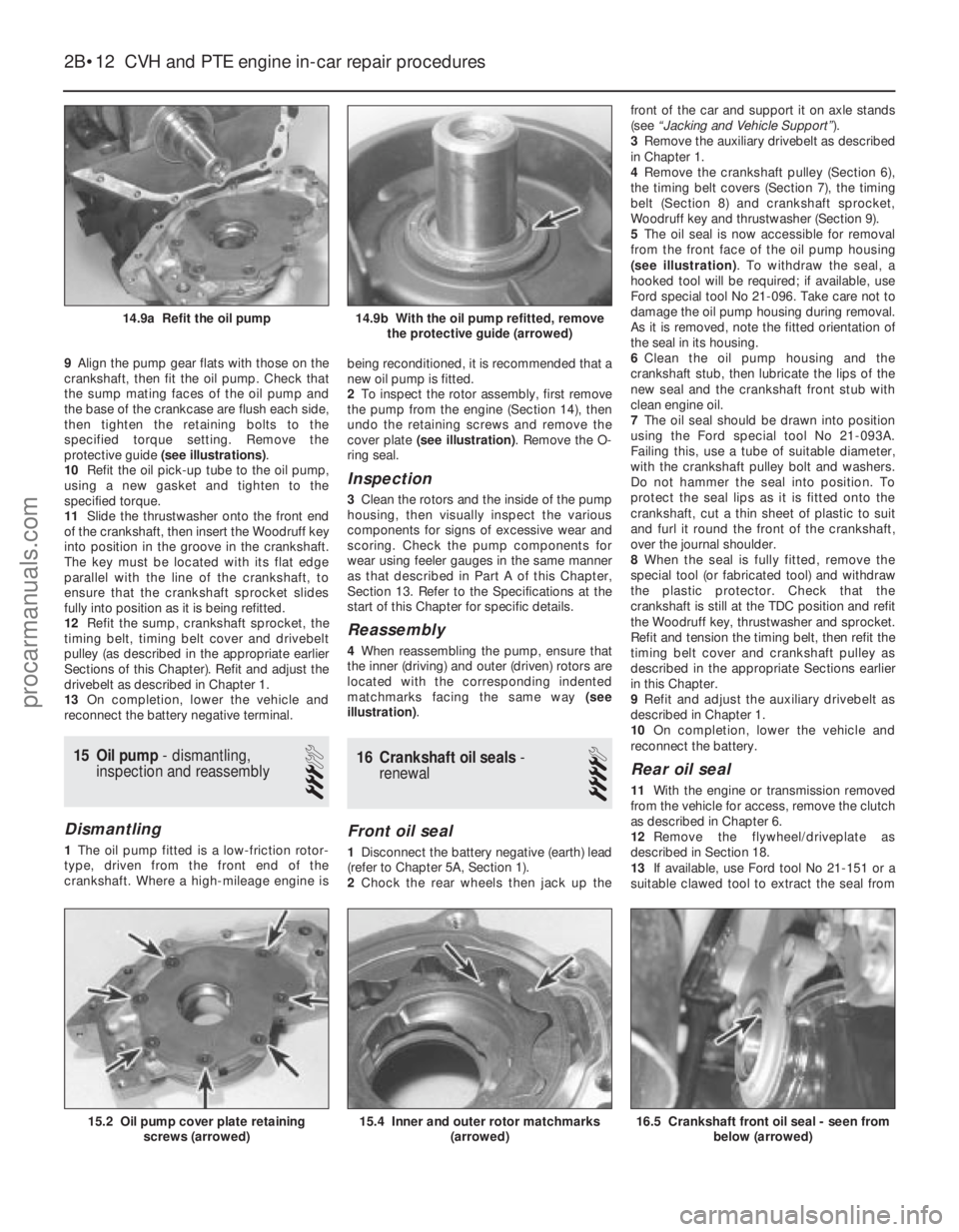
9Align the pump gear flats with those on the
crankshaft, then fit the oil pump. Check that
the sump mating faces of the oil pump and
the base of the crankcase are flush each side,
then tighten the retaining bolts to the
specified torque setting. Remove the
protective guide (see illustrations) .
10 Refit the oil pick-up tube to the oil pump,
using a new gasket and tighten to the
specified torque.
11 Slide the thrustwasher onto the front end
of the crankshaft, then insert the Woodruff key
into position in the groove in the crankshaft.
The key must be located with its flat edge
parallel with the line of the crankshaft, to
ensure that the crankshaft sprocket slides
fully into position as it is being refitted.
12 Refit the sump, crankshaft sprocket, the
timing belt, timing belt cover and drivebelt
pulley (as described in the appropriate earlier
Sections of this Chapter). Refit and adjust the
drivebelt as described in Chapter 1.
13 On completion, lower the vehicle and
reconnect the battery negative terminal.
15 Oil pump - dismantling,
inspection and reassembly
3
Dismantling
1 The oil pump fitted is a low-friction rotor-
type, driven from the front end of the
crankshaft. Where a high-mileage engine is being reconditioned, it is recommended that a
new oil pump is fitted.
2
To inspect the rotor assembly, first remove
the pump from the engine (Section 14), then
undo the retaining screws and remove the
cover plate (see illustration) . Remove the O-
ring seal.
Inspection
3 Clean the rotors and the inside of the pump
housing, then visually inspect the various
components for signs of excessive wear and
scoring. Check the pump components for
wear using feeler gauges in the same manner
as that described in Part A of this Chapter,
Section 13. Refer to the Specifications at the
start of this Chapter for specific details.
Reassembly
4 When reassembling the pump, ensure that
the inner (driving) and outer (driven) rotors are
located with the corresponding indented
matchmarks facing the same way (see
illustration) .
16Crankshaft oil seals -
renewal
4
Front oil seal
1 Disconnect the battery negative (earth) lead
(refer to Chapter 5A, Section 1).
2 Chock the rear wheels then jack up the front of the car and support it on axle stands
(see
“Jacking and Vehicle Support” ).
3 Remove the auxiliary drivebelt as described
in Chapter 1.
4 Remove the crankshaft pulley (Section 6),
the timing belt covers (Section 7), the timing
belt (Section 8) and crankshaft sprocket,
Woodruff key and thrustwasher (Section 9).
5 The oil seal is now accessible for removal
from the front face of the oil pump housing
(see illustration) . To withdraw the seal, a
hooked tool will be required; if available, use
Ford special tool No 21-096. Take care not to
damage the oil pump housing during removal.
As it is removed, note the fitted orientation of
the seal in its housing.
6 Clean the oil pump housing and the
crankshaft stub, then lubricate the lips of the
new seal and the crankshaft front stub with
clean engine oil.
7 The oil seal should be drawn into position
using the Ford special tool No 21-093A.
Failing this, use a tube of suitable diameter,
with the crankshaft pulley bolt and washers.
Do not hammer the seal into position. To
protect the seal lips as it is fitted onto the
crankshaft, cut a thin sheet of plastic to suit
and furl it round the front of the crankshaft,
over the journal shoulder.
8 When the seal is fully fitted, remove the
special tool (or fabricated tool) and withdraw
the plastic protector. Check that the
crankshaft is still at the TDC position and refit
the Woodruff key, thrustwasher and sprocket.
Refit and tension the timing belt, then refit the
timing belt cover and crankshaft pulley as
described in the appropriate Sections earlier
in this Chapter.
9 Refit and adjust the auxiliary drivebelt as
described in Chapter 1.
10 On completion, lower the vehicle and
reconnect the battery.
Rear oil seal
11 With the engine or transmission removed
from the vehicle for access, remove the clutch
as described in Chapter 6.
12 Remove the flywheel/driveplate as
described in Section 18.
13 If available, use Ford tool No 21-151 or a
suitable clawed tool to extract the seal from
2B•12 CVH and PTE engine in-car repair procedures
16.5 Crankshaft front oil seal - seen from
below (arrowed)15.4 Inner and outer rotor matchmarks (arrowed)15.2 Oil pump cover plate retainingscrews (arrowed)
14.9b With the oil pump refitted, removethe protective guide (arrowed)14.9a Refit the oil pump
1595Ford Fiesta Remakeprocarmanuals.com
http://vnx.su
Page 52 of 296
its housing. If the seal housing is removed
from the rear face of the engine, the seal can
be removed as described in paragraph 18. As
it is removed, note the direction of fitting, and
take care not to damage the seal housing as
the seal is extracted.
14Clean the seal housing, the crankshaft
rear flange face, and the flywheel/driveplate
mating surfaces.
15 One of two possible methods may be
used to insert the new oil seal, depending on
the tools available.
16 If Ford special service tool No 21-095 is
available, lubricate the seal lips of the seal and
its running face on the crankshaft with clean
engine oil. Position the seal (correctly
orientated) into the special tool, then draw the
seal into the housing using two
flywheel/driveplate securing bolts so that the
seal is against the stop.
17 If the correct Ford service tool is not
available, it will be necessary to remove the oil
seal carrier housing. To do this, first remove
the sump as described in Section 13, then
unscrew the seal housing retaining bolts and
remove the housing from the rear face of the
crankcase.
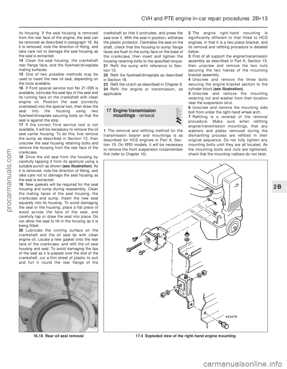
18 Drive the old seal from the housing by
carefully tapping it from its aperture using a
suitable punch as shown (see illustration). As
it is removed, note the direction of fitting, and
take care not to damage the seal housing as
the seal is extracted.
19 New gaskets will be required for the seal
housing and sump during reassembly. Clean
the mating faces of the seal housing, the
crankcase and sump. Insert the new seal
squarely into its housing. To avoid damaging
the seal or the housing, place a flat piece of
wood across the face of the seal, and
carefully tap or draw the seal into place. Do
not allow the seal to tilt in the housing as it is
being fitted.
20 Lubricate the running surface on the
crankshaft and the oil seal lip with clean
engine oil. Locate a new gasket onto the rear
face of the crankcase, and refit the oil seal
housing and seal. To avoid damaging the lips
of the seal as it is passed over the end of the
crankshaft, cut a thin sheet of plastic to suit
and furl it round the rear flange of the crankshaft so that it protrudes, and press the
seal over it. With the seal in position, withdraw
the plastic protector. Centralise the seal on the
shaft, check that the housing-to-sump flange
faces are flush to the sump face on the base of
the crankcase, then insert and tighten the
housing retaining bolts to the specified torque.
21
Refit the sump with reference to Sec-
tion 13.
22 Refit the flywheel/driveplate as described
in Section 18.
23 Refit the clutch as described in Chapter 6.
24 Refit the engine or transmission, as
applicable.
17 Engine/transmission mountings - renewal
2
1The removal and refitting method for the
transmission bearer and mountings is as
described for HCS engines in Part A, Sec-
tion 15. On XR2i models, it will be necessary
to remove the front suspension crossmember
first (refer to Chapter 10). 2
The engine right-hand mounting is
significantly different to that fitted to HCS
engines, in that it is a two-piece bracket, and
its removal and refitting procedure is detailed
below.
3 First of all support the engine/transmission
assembly as described in Part A, Section 15,
then unscrew and remove the two nuts
securing the two halves of the mounting
bracket assembly.
4 Unscrew and remove the three bolts
securing the engine bracket section to the
cylinder block (see illustration) .
5 Unscrew and remove the mounting
retaining nut and washer from their location
near the suspension strut.
6 Unscrew and remove the mounting side
bolt from under the right-hand wheel arch.
7 Refitting is a reversal of the removal
procedure. Make sure when refitting
engine/transmission mountings, that any
washers and plates removed during the
dismantling process are refitted in their
original sequence. Do not fully tighten any
mounting bolts until they are all located. As
the mounting bolts and nuts are tightened,
check that the mounting rubbers do not twist.
CVH and PTE engine in-car repair procedures 2B•13
17.4 Exploded view of the right-hand engine mounting16.18 Rear oil seal removal
2B
1595Ford Fiesta Remakeprocarmanuals.com
http://vnx.su