1989 FORD FIESTA service reset
[x] Cancel search: service resetPage 61 of 296
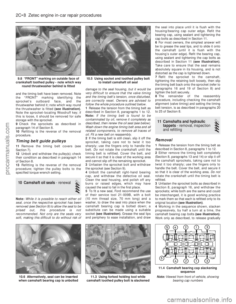
and the timing belt have been removed. Note
the “FRONT” marking identifying the
sprocket’s outboard face, and the
thrustwasher behind it; note which way round
the thrustwasher is fitted (see illustration).
Note the sprocket-locating Woodruff key; if
this is loose, it should be removed for safe
storage with the sprocket.
9 Check the sprockets as described in
paragraph 14 of Section 8.
10 Refitting is the reverse of the removal
procedure.
Timing belt guide pulleys
11 Remove the timing belt covers (see
Section 7).
12 Unbolt and withdraw the pulley(s); check
their condition as described in paragraph 14
of Section 8.
13 Refitting is the reverse of the removal
procedure; tighten the pulley bolts to the
specified torque wrench setting.
10 Camshaft oil seals - renewal
4
Note:While it is possible to reach either oil
seal, once the respective sprocket has been
removed (see Section 9) to allow the seal to be
prised out, this procedure is not
recommended. Not only are the seals very
soft, making this difficult to do without risk of damage to the seal housing, but it would be
very difficult to ensure that the valve timing
and the timing belt’s tension, once disturbed,
are correctly reset. Owners are advised to
follow the whole procedure outlined below.
1
Release the tension from the timing belt as
described in Section 8, paragraphs 1 to 12.
Note: If the timing belt is found to be
contaminated by oil, remove it completely as
described, then renew the oil seal (see below).
Wash down the engine timing belt area and all
related components, to remove all traces of
oil. Fit a new belt on reassembly.
2 If the timing belt is still clean, slip it off the
sprocket, taking care not to twist it too
sharply; use the fingers only to handle the
belt. Do not rotate the crankshaft until the
timing belt is refitted. Cover the belt, and
secure it so that it is clear of the working area
and cannot slip off the remaining sprocket.
3 Unfasten the sprocket bolt and withdraw
the sprocket (see Section 9).
4 Unbolt the camshaft right-hand bearing
cap, and withdraw the defective oil seal.
Clean the seal housing, and polish off any
burrs or raised edges, which may have
caused the seal to fail in the first place.
5 To fit a new seal, Ford recommend the use
of their service tool 21-009B, with a bolt
(10 mm thread size, 70 mm long) and a
washer, to draw the seal into place when the
camshaft bearing cap is bolted down; a
substitute can be made using a suitable
socket (see illustration) . Grease the seal lips
and periphery to ease installation, and draw the seal into place until it is flush with the
housing/bearing cap outer edge. Refit the
bearing cap, using sealant and tightening the
cap bolts as described in Section 11.
6
For most owners, the simplest answer will
be to grease the seal lips, and to slide it onto
the camshaft (until it is flush with the
housing’s outer edge). Refit the bearing cap,
using sealant and tightening the cap bolts as
described in Section 11 (see illustration).
Take care to ensure that the seal remains
absolutely square in its housing, and is not
distorted as the cap is tightened down.
7 Refit the sprocket to the camshaft,
tightening the retaining bolt loosely, then slip
the timing belt back onto the sprocket (refer to
paragraphs 16 and 19 of Section 8) and
tighten the bolt securely.
8 The remainder of the reassembly
procedure, including checking the camshaft
alignment (valve timing) and setting the timing
belt tension, is as described in paragraphs 20
to 25 of Section 8.
11 Camshafts and hydraulic tappets - removal, inspection
and refitting
4
Removal
1 Release the tension from the timing belt as
described in Section 8, paragraphs 1 to 12.
2 Either remove the timing belt completely
(Section 8, paragraphs 13 and 14) or slip it off
the camshaft sprockets, taking care not to
twist it too sharply; use the fingers only to
handle the belt. Cover the belt, and secure it
so that it is clear of the working area. Do not
rotate the crankshaft until the timing belt is
refitted.
3 Unfasten the sprocket bolts as described in
Section 8, paragraph 16, and withdraw the
sprockets; while both are the same and could
be interchanged, it is good working practice
to mark them so that each is refitted only to its
original location (see illustration) .
4 Working in the sequence shown, slacken
progressively, by half a turn at a time, the
camshaft bearing cap bolts (see illustration).
Work only as described, to release gradually
2C•8 Zetec engine in-car repair procedures
11.4 Camshaft bearing cap slackening
sequence
Note: Viewed from front of vehicle, showing
bearing cap numbers
11.3 Using forked holding tool while
camshaft toothed pulley bolt is slackened10.6 Alternatively, seal can be inserted
when camshaft bearing cap is unbolted
10.5 Using socket and toothed pulley bolt to install camshaft oil seal9.8 “FRONT” marking on outside face of
crankshaft toothed pulley - note which way round thrustwasher behind is fitted
1595Ford Fiesta Remakeprocarmanuals.com
http://vnx.su
Page 127 of 296
4 Air cleaner assembly and airinlet components -
removal and refitting
1
Note: Air cleaner element renewal and air
cleaner temperature control system checks
(where applicable) are described in Chapter 1.
Air cleaner assembly
1 Disconnect the battery negative (earth) lead
(refer to Chapter 5A, Section 1).
2 Undo the retaining bolts and partially lift the
air cleaner from the CFi unit, so that the hose
and wiring connections to the underside of
the air cleaner body are accessible.
3 Note their connections and routings, then
detach the wiring and hoses from the
underside of the air cleaner.
4 Lift the air cleaner clear from the CFi unit.
5 Refit in the reverse order of removal.
6 Renew any hoses that are perished or
cracked, and ensure that all fittings are
securely and correctly reconnected.
Air inlet components
7 The air cleaner inlet spout and related
components are removed with the air cleaner
assembly as described above.
5 Accelerator cable - removal,
refitting and adjustment
1
Removal
1 Disconnect the battery negative (earth) lead
(refer to Chapter 5A, Section 1).
2 Fold back the carpet and insulation in the
driver’s footwell to gain access to the
accelerator pedal.
3 Detach the accelerator cable from the
pedal.
4 Remove the air cleaner assembly as
described in Section 4.
5 Working at the throttle housing end of the
cable, pivot the throttle quadrant by hand to
release the tension from the cable, then
detach the inner cable nipple from the throttle
lever.
6 Detach the outer cable from the
adjuster/support bracket, then remove the
cable.
Refitting and adjustment
7 Refit in the reverse order of removal. When
the cable is reconnected at each end, have an
assistant depress the accelerator, and check
that the throttle fully opens and shuts without
binding. Ensure that there is a small amount of
slack in the inner cable when the throttle is
fully released. If adjustment is required,
release the outer cable retaining clip from the
cable at the adjustment/support bracket, slide
the cable through the adjuster grommet to the
point required, then refit the retaining clip to
secure it in the set position.
6 Accelerator pedal -
removal and refitting
1
Refer to Part A, Section 5.
7 Fuel pump/fuel pressure -
checking
3
Note: Refer to the warning note in Section 1
before proceeding.
Fuel pump operation check
1 Switch on the ignition, and listen for the fuel
pump (the sound of an electric motor running,
audible from beneath the rear seats). Assuming
there is sufficient fuel in the tank, the pump
should start and run for approximately one or
two seconds, then stop, each time the ignition
is switched on. Note:If the pump runs
continuously all the time the ignition is switched
on, the electronic control system is running in
the backup (or “limp-home”) mode referred to
by Ford as “Limited Operation Strategy” (LOS).
This almost certainly indicates a fault in the
EEC IV module itself, and the vehicle should
therefore be taken to a Ford dealer for a full test
of the complete system, using the correct
diagnostic equipment; do not waste time or risk
damaging the components by trying to test the
system without such facilities.
2 Listen for fuel return noises from the fuel
pressure regulator. It should be possible to
feel the fuel pulsing in the regulator and in the
feed hose from the fuel filter.
3 If the pump does not run at all, check the
fuse, relay and wiring (see Chapter 12). Check
also that the fuel cut-off switch has not been
activated and if so, reset it.
Fuel pressure check
4 A fuel pressure gauge will be required for this
check and should be connected in the fuel line
between the fuel filter and the CFi unit, in
accordance with the gauge maker’s instructions.
5 Start the engine and allow it to idle. Note
the gauge reading as soon as the pressure
stabilises, and compare it with the figures
given for regulated fuel pressure in the
Specifications . If the pressure is high, check
for a restricted fuel return line. If the pressure
is low, renew the fuel pressure regulator. 6
Switch off the engine, and check that after
one minute, the hold pressure has not fallen
below that specified. If it has, check the seals
on the fuel injector (see Section 14) and renew
them if they appear in any way suspect. If the
seals are okay, then the fuel pressure
regulator or CFi unit are suspect.
7 Carefully disconnect the fuel pressure
gauge, depressurising the system first as
described in Section 2.
8 Run the engine, and check that there are no
fuel leaks.
8 Fuel tank - removal,
inspection and refitting
3
Proceed as described in Part A, Section 8, but
before disconnecting the battery, relieve the
residual pressure in the fuel system (see Sec-
tion 2), and equalise tank pressure by removing
the fuel filler cap. Note also that it will be
necessary to release any additional ventilation
tubes from their retaining clips, and to reposition
or remove the underbody heat shields on certain
models for access to the tank retaining bolts.
9 Fuel pump/fuel gauge
sender unit - removal and
refitting
3
Note: Refer to the warning note in Section 1
before proceeding. Ford specify the use of their
service tool 23-026 (a large box spanner with
projecting teeth to engage the fuel pump/sender
unit retaining ring’s slots) for this task. While
alternatives are possible, in view of the difficulty
experienced in removing and refitting the
pump/sender unit, it is strongly advised that the
correct tool is obtained before starting work.
Removal
1 A combined fuel pump and fuel gauge
sender unit are located in the top face of the
fuel tank. The combined unit can only be
detached and withdrawn from the tank after
the tank is released and lowered from
under the vehicle. Refer to Section 8 and
remove the fuel tank, then proceed as follows.
2 With the fuel tank removed, the
pump/sender unit can be unscrewed using
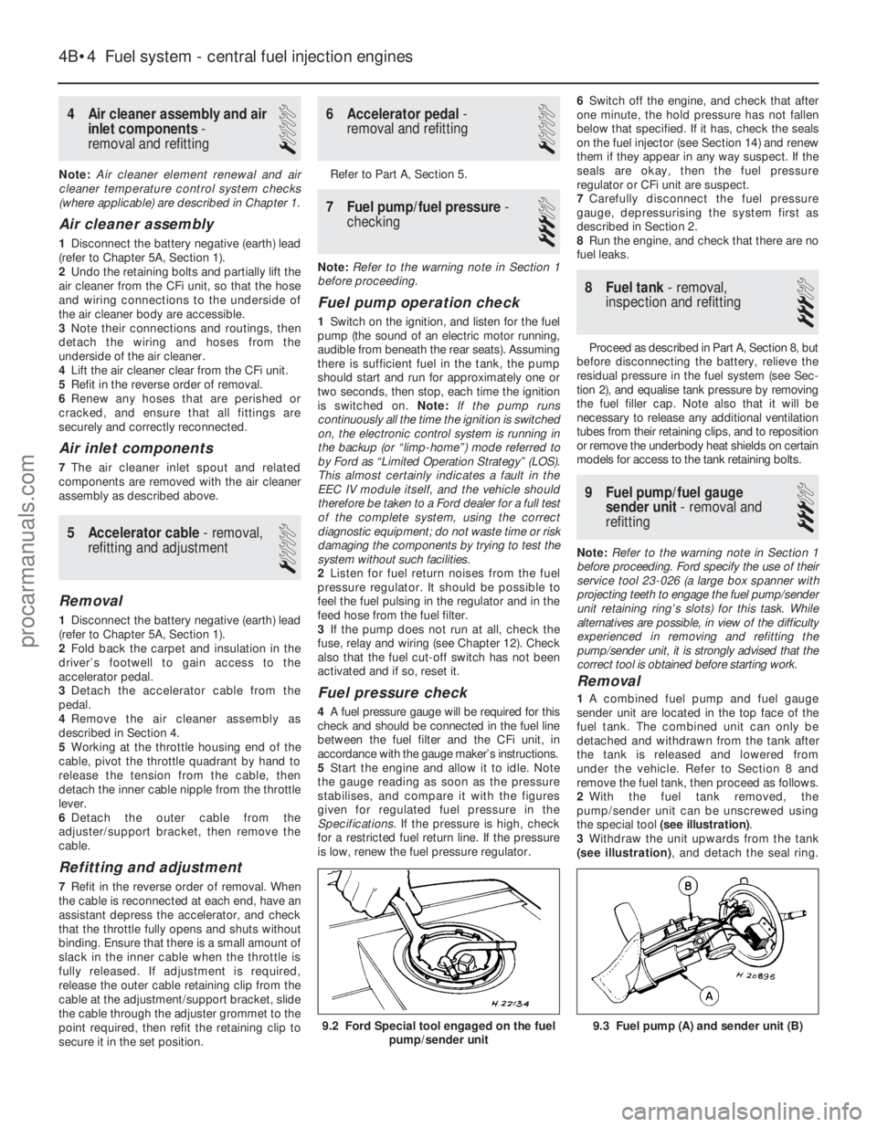
the special tool (see illustration) .
3 Withdraw the unit upwards from the tank
(see illustration) , and detach the seal ring.
9.3 Fuel pump (A) and sender unit (B)
4B•4 Fuel system - central fuel injection engines
9.2 Ford Special tool engaged on the fuel
pump/sender unit
1595Ford Fiesta Remakeprocarmanuals.com
http://vnx.su
Page 147 of 296
7 Fuel pump/fuel pressure-
checking
3
Note: Refer to the warning note in Section 1
before proceeding.
Fuel pump operation check
1 Switch on the ignition, and listen for the fuel
pump (the sound of an electric motor running,
audible from beneath the rear seats).
Assuming there is sufficient fuel in the tank,
the pump should start and run for
approximately one or two seconds, then stop,
each time the ignition is switched on. Note:If
the pump runs continuously all the time the
ignition is switched on, the electronic control
system is running in the backup (or “limp-
home”) mode referred to by Ford as “Limited
Operation Strategy” (LOS). This almost
certainly indicates a fault in the EEC IV module
itself, and the vehicle should therefore be
taken to a Ford dealer for a full test of the
complete system, using the correct diagnostic
equipment; do not waste time or risk
damaging the components by trying to test
the system without such facilities.
2 Listen for fuel return noises from the fuel
pressure regulator. It should be possible to
feel the fuel pulsing in the regulator and in the
feed hose from the fuel filter.
3 If the pump does not run at all, check the
fuse, relay and wiring (see Chapter 12). Check
also that the fuel cut-off switch has not been
activated and if so, reset it.
Fuel pressure check
4 A fuel pressure gauge will be required for
this check and should be connected in the
fuel line between the fuel filter and the fuel rail,
in accordance with the gauge maker’s
instructions. On Zetec engines, a pressure
gauge equipped with an adapter to suit the
Schrader-type valve on the fuel rail pressure
test/release fitting (identifiable by its blue
plastic cap, and located on the union of the
fuel feed line and the fuel rail) will be required.
If the Ford special tool 29-033 is available, the
tool can be attached to the valve, and a
conventional-type pressure gauge attached to
the tool.
5 If using the service tool, ensure that its tap
is turned fully anti-clockwise, then attach it to
the valve. Connect the pressure gauge to the
service tool. If using a fuel pressure gauge
with its own adapter, connect it in accordance
with its maker’s instructions.
6 Start the engine and allow it to idle. Note
the gauge reading as soon as the pressure
stabilises, and compare it with the regulated
fuel pressure figures listed in the
Specifications .
a) If the pressure is high, check for a
restricted fuel return line. If the line is
clear, renew the fuel pressure regulator.
b) If the pressure is low, pinch the fuel return
line. If the pressure now goes up, renew the fuel pressure regulator. If the pressure
does not increase, check the fuel feed
line, the fuel pump and the fuel filter.
7 Detach the vacuum hose from the fuel
pressure regulator; the pressure shown on the
gauge should increase. Note the increase in
pressure, and compare it with that listed in the
Specifications . If the pressure increase is not
as specified, check the vacuum hose and
pressure regulator.
8 Reconnect the regulator vacuum hose, and
switch off the engine. Verify that the hold
pressure stays at the specified level for five
minutes after the engine is turned off.
9 Carefully disconnect the fuel pressure
gauge, depressurising the system first as
described in Section 2. Be sure to cover the
fitting with a rag before slackening it. Mop up
any spilt petrol.
10 Run the engine, and check that there are
no fuel leaks.
8 Fuel tank - removal,
inspection and refitting
3
Proceed as described in Part A, Section 8,
but before disconnecting the battery, relieve
the residual pressure in the fuel system (see
Section 2), and equalise tank pressure by
removing the fuel filler cap.
9 Fuel pump/fuel gauge sender unit - removal and
refitting
3
Refer to Part B, Section 9.
10 Fuel tank ventilation tube -
removal and refitting
3
Refer to Part A, Section 10, but note that
the ventilation tube connects to the combined
roll-over/anti-trickle-fill valve assembly but,
instead of venting to atmosphere, a further
tube runs the length of the vehicle to the
evaporative emission control system carbon canister in the front right-hand corner of the
engine compartment.
Further information on the evaporative
emission control system is contained in Part E
of this Chapter.
11 Fuel tank filler pipe -
removal and refitting
3
Refer to Part A, Section 11.
12 Fuel cut-off switch -
removal and refitting
1
Refer to Part B, Section 12.
13 Fuel injection system -
checking
3
Refer to Part B, Section 13
14 Fuel injection system components - removal and
refitting
3
Note: Refer to the warning note in Section 1
before proceeding.
Throttle housing
1 Disconnect the battery negative (earth) lead
(refer to Chapter 5A, Section 1).
2 Remove the air inlet components as
described in Section 4.
3 Disconnect the accelerator cable from the
throttle linkage (see Section 5).
4 Disconnect the throttle position sensor
multi-plug.
5 Unscrew the retaining bolts, and detach the
accelerator cable support bracket at the
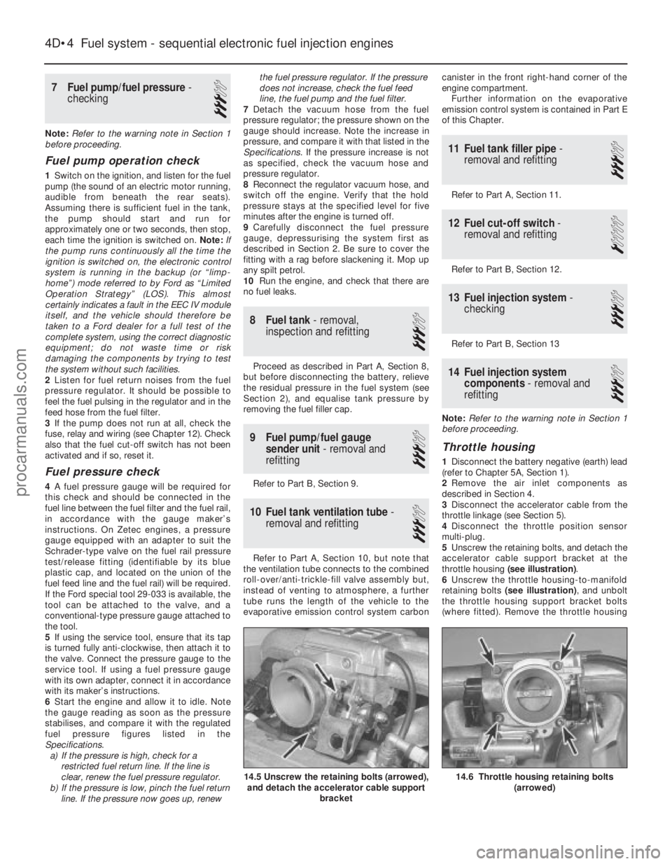
throttle housing (see illustration) .
6 Unscrew the throttle housing-to-manifold
retaining bolts (see illustration) , and unbolt
the throttle housing support bracket bolts
(where fitted). Remove the throttle housing
4D•4 Fuel system - sequential electronic fuel injection engines
14.6 Throttle housing retaining bolts
(arrowed)14.5 Unscrew the retaining bolts (arrowed),and detach the accelerator cable support
bracket
1595Ford Fiesta Remakeprocarmanuals.com
http://vnx.su
Page 170 of 296
flux can pass between the magnet and the
sensor. When a trigger vane segment is in line
with the sensor, the magnetic flux is diverted
through the trigger vane, away from the
sensor. The sensor detects the change in
magnetic flux and sends an impulse to the
EEC IV module. Additional data is received
from the engine coolant temperature sensor,
manifold absolute pressure sensor, inlet air
temperature sensor, throttle position sensor
and vehicle speed sensor. Using this
information the EEC IV module calculates the
optimum ignition advance setting and
switches off the low tension circuit via the
ignition module. This results in the collapse of
the magnetic field in the coil which generates
the high tension voltage. The high tension
voltage is then fed, via the coil HT lead and
the carbon brush in the centre of the
distributor cap, to the rotor arm. The voltage
passes across to the appropriate metal
segment in the cap and via the spark plug HT
lead to the spark plug where it finally jumps
the spark plug gap to earth. It can be seen
that the ignition module functions basically as
a high current switch by controlling the low
tension supply to the ignition coil primary
windings.In the event of failure of a sensor, the
EEC IV module will substitute a preset value
for that input to allow the system to continue
to function. In the event of failure of the
EEC IV module, a “limited operation strategy”
(LOS) function allows the vehicle to be driven,
albeit at reduced power and efficiency. The
EEC IV module also has a “keep alive
memory” (KAM) function which stores idle and
drive values and codes which can be used to
indicate any system fault which may occur.
Distributorless ignition systems
The main ignition system components
include the ignition switch, the battery, the
crankshaft speed/position sensor, the ignition
module, the coil, the primary (low tension/LT)
and secondary (high tension/HT) wiring
circuits, and the spark plugs. The system used on carburettor models is
termed DIS (Distributorless Ignition System),
and on fuel injection models E-DIS, (Electronic
Distributorless Ignition System). The primary
difference between the two is that the DIS
system is an independent ignition control
system while the E-DIS system operates in
conjunction with the EEC IV engine
management module which also controls the
fuel injection and emission control systems.
With both systems, the main functions of
the distributor are replaced by a computerised
ignition module and a coil unit. The coil unit
combines a double-ended pair of coils - each
time a coil receives an ignition signal, two
sparks are produced, at each end of the
secondary windings. One spark goes to a
cylinder on compression stroke and the other
goes to the corresponding cylinder on its
exhaust stroke. The first will give the correct power stroke, but the second spark will have
no effect (a “wasted spark”), occurring as it
does during exhaust conditions.
The ignition signal is generated by a
crankshaft position sensor which scans a
series of 36 protrusions on the periphery of
the engine flywheel. The inductive head of the
crankshaft position sensor runs just above the
flywheel periphery and as the crankshaft
rotates, the sensor transmits a pulse to the
ignition module every time a protrusion
passes it. There is one missing protrusion in
the flywheel periphery at a point
corresponding to 90° BTDC. The ignition
module recognises the absence of a pulse
from the crankshaft position sensor at this
point to establish a reference mark for
crankshaft position. Similarly, the time interval
between absent pulses is used to determine
engine speed. On carburettor engines, the ignition module
receives signals provided by information
sensors which monitor various engine
functions (such as crankshaft position,
coolant temperature, inlet air temperature,
inlet manifold vacuum etc). This information
allows the ignition module to generate the
optimum ignition timing setting under all
operating conditions.
On fuel injection engines, the ignition
module operates in conjunction with the
EEC IV engine management module, and
together with the various additional
information sensors and emission control
components, provides total control of the fuel
and ignition systems to form a complete
engine management package. The information contained in this Chapter
concentrates on the ignition-related
components of the engine management
system. Information covering the fuel, exhaust
and emission control components can be
found in the applicable Parts of Chapter 4.
Precautions
When working on the ignition system, take
the following precautions:
a) Do not keep the ignition switch on for
more than 10 seconds if the engine will
not start.
b) If a separate tachometer is ever required
for servicing work, consult a dealer
service department before buying a
tachometer for use with this vehicle -
some tachometers may be incompatible
with these types of ignition systems - and
always connect it in accordance with the
equipment manufacturer’s instructions.
c) Never connect the ignition coil terminals to earth. This could result in damage to
the coil and/or the ignition module.
d) Do not disconnect the battery when the
engine is running.
e) Make sure that the ignition module is
properly earthed.
f) Refer to the warning at the beginning of the next Section concerning HT voltage.
2 Ignition system - testing
2
Warning: Voltages produced by
an electronic ignition system are
considerably higher than those
produced by conventional
ignition systems. Extreme care must be
taken when working on the system with
the ignition switched on. Persons with
surgically-implanted cardiac pacemaker
devices should keep well clear of the
ignition circuits, components and test
equipment.
Note: Refer to the precautions given in
Section 1 of Part A of this Chapter before
starting work. Always switch off the ignition
before disconnecting or connecting any
component and when using a multi-meter to
check resistances.
1 If the engine turns over but won’t start,
disconnect the (HT) lead from any spark plug,
and attach it to a calibrated tester (available at
most automotive accessory shops). Connect
the clip on the tester to a good earth - a bolt
or metal bracket on the engine. If you’re
unable to obtain a calibrated ignition tester,
have the check carried out by a Ford dealer
service department or similar. Any other form
of testing (such as jumping a spark from the
end of an HT lead to earth) is not
recommended, because of the risk of
personal injury, or of damage to the ignition
module.
2 Crank the engine, and watch the end of the
tester to see if bright blue, well-defined sparks
occur.
3 If sparks occur, sufficient voltage is
reaching the plug to fire it. Repeat the
check at the remaining plugs, to ensure
that all leads are sound and that the
coil is serviceable. However, the plugs
themselves may be fouled or faulty, so
remove and check them as described in
Chapter 1.
4 If no sparks or intermittent sparks occur,
the spark plug lead(s) may be defective. Also,
on distributor systems, there may be
problems with the rotor arm or distributor cap
- check all these components as described in
Chapter 1.
5 If there’s still no spark, check the coil’s
electrical connector (where applicable), to
make sure it’s clean and tight. Check for full
battery voltage to the coil at the connector’s
centre terminal. Check the coil itself (see
Section 3). Make any necessary repairs, then
repeat the check again.
6 The remainder of the system checks should
be left to a dealer service department
or other qualified repair facility, as there is a
chance that the ignition module may
be damaged if tests are not performed
properly.
Ignition system 5B•3
5B
1595Ford Fiesta Remakeprocarmanuals.com
http://vnx.su
Page 244 of 296
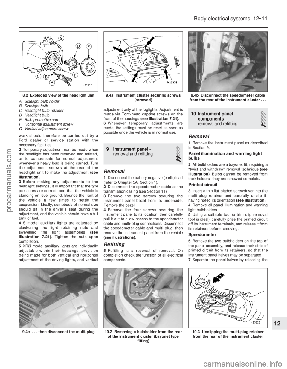
work should therefore be carried out by a
Ford dealer or service station with the
necessary facilities.
2Temporary adjustment can be made when
the headlight has been removed and refitted,
or to compensate for normal adjustment
whenever a heavy load is being carried. Turn
the adjustment screws at the rear of the
headlight unit to make the adjustment (see
illustration) .
3 Before making any adjustments to the
headlight settings, it is important that the tyre
pressures are correct, and that the vehicle is
standing on level ground. Bounce the front of
the vehicle a few times to settle the
suspension. Ideally, somebody of normal size
should sit in the driver’s seat during the
adjustment, and the vehicle should have a full
tank of fuel.
4 S model auxiliary lights are adjusted by
slackening the light retaining nuts and
swivelling the light assemblies (see
illustration 7.21) . Tighten the nuts upon
completion.
5 XR2i model auxiliary lights are individually
adjustable within their housings, provision
being made for both vertical and horizontal
adjustment of the driving lights, and vertical adjustment only of the foglights. Adjustment is
made via Torx-head captive screws on the
front of the housings
(see illustration 7.24) .
6 Whenever temporary adjustments are
made, the settings must be reset as soon as
possible once the vehicle is in normal use.
9 Instrument panel -
removal and refitting
2
Removal
1 Disconnect the battery negative (earth) lead
(refer to Chapter 5A, Section 1).
2 Disconnect the speedometer cable at the
transmission casing (see Section 11).
3 Remove the two screws securing the
instrument panel bezel from its underside.
Remove the bezel.
4 Remove the four screws securing the
instrument panel to its location, then carefully
pull it out to allow access to the speedometer
cable and multi-plug connections. Disconnect
the speedometer cable and multi-plug, then
remove the instrument panel from the vehicle
(see illustrations) .
Refitting
5Refitting is a reversal of removal. On
completion check the function of all electrical
components.
10 Instrument panel
components -
removal and refitting
1
Removal
1 Remove the instrument panel as described
in Section 9.
Panel illumination and warning light
bulbs
2 All bulbholders are a bayonet fit, requiring a
“twist and withdraw” removal technique (see
illustration) . Bulbs cannot be removed from
their holders -they are renewed complete.
Printed circuit
3 Insert a thin flat-bladed screwdriver into the
multi-plug retainer and carefully unclip it,
having noted its orientation (see illustration).
4 Remove all panel illumination and warning
light bulbholders.
5 Using a suitable tool (a trim clip removal
tool is ideal), carefully prise the printed circuit
off its instrument terminals, and release it from
its retainers before removing.
Speedometer
6 Remove the two bulbholders on the top of
the panel assembly, and release their strip of
printed circuit from its retainers, so that the
instrument panel halves may be separated.
7 Separate the panel halves by releasing the
Body electrical systems 12•11
9.4b Disconnect the speedometer cable
from the rear of the instrument cluster . . .9.4a Instrument cluster securing screws (arrowed)8.2 Exploded view of the headlight unit
A Sidelight bulb holder
B Sidelight bulb
C Headlight bulb retainer
D Headlight bulb
E Bulb protective cap
F Horizontal adjustment screw
G Vertical adjustment screw
10.3 Unclipping the multi-plug retainer from the rear of the instrument cluster10.2 Removing a bulbholder from the rear of the instrument cluster (bayonet type
fitting)9.4c . . . then disconnect the multi-plug
12
1595Ford Fiesta Remakeprocarmanuals.com
http://vnx.su