1989 FORD FIESTA rims
[x] Cancel search: rimsPage 17 of 296

lubricant, together with dirt and water entry,
resulting in rapid deterioration of the balljoints
or steering gear.
3Check the power-assisted steering fluid
hoses (where fitted) for chafing or
deterioration, and the pipe and hose unions
for fluid leaks. Also check for signs of fluid
leakage under pressure from the steering gear
rubber gaiters, which would indicate failed
fluid seals within the steering gear.
4 Grasp the roadwheel at the 12 o’clock and
6 o’clock positions, and try to rock it. Very
slight free play may be felt, but if the
movement is appreciable, further investigation
is necessary to determine the source.
Continue rocking the wheel while an assistant
depresses the footbrake. If the movement is
now eliminated or significantly reduced, it is
likely that the hub bearings are at fault. If the
free play is still evident with the footbrake
depressed, then there is wear in the
suspension joints or mountings.
5 Now grasp the wheel at the 9 o’clock and 3
o’clock positions, and try to rock it as before.
Any movement felt now may again be caused
by wear in the hub bearings or the steering
track rod balljoints. If the outer track rod end
balljoint is worn, the visual movement will be
obvious. If the inner joint is suspect, it can be
felt by placing a hand over the rack-and-
pinion rubber gaiter, and gripping the track
rod. If the wheel is now rocked, movement will
be felt at the inner joint if wear has taken
place.
6 Using a large screwdriver or flat bar, check
for wear in the suspension mounting bushes
by levering between the relevant suspension
component and its attachment point. Some
movement is to be expected, as the
mountings are made of rubber, but excessive
wear should be obvious. Also check the
condition of any visible rubber bushes,
looking for splits, cracks or contamination of
the rubber.
7 With the vehicle standing on its wheels,
have an assistant turn the steering wheel
back-and-forth, about an eighth of a turn each
way. There should be very little, if any, lost
movement between the steering wheel and
roadwheels. If this is not the case, closely
observe the joints and mountings previously described, but in addition, check the steering
column universal joints for wear, and also
check the rack-and-pinion steering gear itself.
Rear suspension check
8
Chock the front wheels then jack up the
rear of the car and support it on axle stands
(see “Jacking and Vehicle Support” ). Remove
the rear roadwheels.
9 Check the rear hub bearings for wear, using
the method described for the front hub
bearings (paragraph 4).
10 Using a large screwdriver or flat bar,
check for wear in the suspension mounting
bushes by levering between the relevant
suspension component and its attachment
point. Some movement is to be expected, as
the mountings are made of rubber, but
excessive wear should be obvious. Check the
condition of the shock absorbers and their
bushes/mountings. On Van models, check the
leaves of the leaf springs for signs of cracking,
distortion, or other damage.
Roadwheel check and balancing
11 Periodically remove the roadwheels, and
clean any dirt or mud from the inside and
outside surfaces. Examine the wheel rims for
signs of rusting, corrosion or other damage.
Light alloy wheels are easily damaged by
“kerbing” whilst parking, and similarly, steel
wheels may become dented or buckled.
Renewal of the wheel is very often the only
course of remedial action possible.
12 The balance of each wheel and tyre
assembly should be maintained, not only to
avoid excessive tyre wear, but also to avoid
wear in the steering and suspension
components. Wheel imbalance is normally
signified by vibration through the vehicle’s
bodyshell, although in many cases it is
particularly noticeable through the steering
wheel. Conversely, it should be noted that
wear or damage in suspension or steering
components may cause excessive tyre wear.
Out-of-round or out-of-true tyres, damaged
wheels and wheel bearing wear/
maladjustment also fall into this category.
Balancing will not usually cure vibration
caused by such wear.
13 Wheel balancing may be carried out with
the wheel either on or off the vehicle. If balanced on the vehicle, ensure that the
wheel-to-hub relationship is marked in some
way prior to subsequent wheel removal, so
that it may be refitted in its original position.
11 Driveshaft rubber gaiter and
CV joint check
1
1The driveshaft rubber gaiters are very
important, because they prevent dirt, water
and foreign material from entering and
damaging the constant velocity (CV) joints.
External contamination can cause the gaiter
material to deteriorate prematurely, so it’s a
good idea to wash the gaiters with soap and
water occasionally.
2 With the vehicle raised and securely
supported on axle stands, turn the steering
onto full-lock, then slowly rotate each front
wheel in turn. Inspect the condition of the
outer constant velocity (CV) joint rubber
gaiters, squeezing the gaiters to open out the
folds. Check for signs of cracking, splits, or
deterioration of the rubber, which may allow
the escape of grease, and lead to the ingress
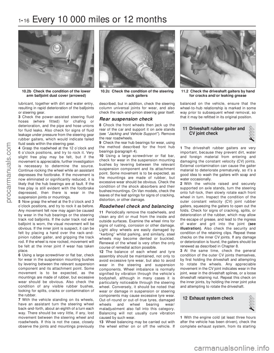
of water and grit into the joint (see
illustration) . Also check the security and
condition of the retaining clips. Repeat these
checks on the inner CV joints. If any damage
or deterioration is found, the gaiters should be
renewed as described in Chapter 8.
3 At the same time, check the general
condition of the outer CV joints themselves,
by first holding the driveshaft and attempting
to rotate the wheels. Any appreciable
movement in the CV joint indicates wear in the
joint, wear in the driveshaft splines, or a loose
driveshaft retaining nut. Repeat this check on
the inner joints, by holding the inner joint yoke
and attempting to rotate the driveshaft.
12 Exhaust system check
1
1 With the engine cold (at least three hours
after the vehicle has been driven), check the
complete exhaust system, from its starting
1•16Every 10 000 miles or 12 months
11.2 Check the driveshaft gaiters by hand for cracks and/or leaking grease10.2c Check the condition of the steering rack gaiters10.2b Check the condition of the lowerarm balljoint dust cover (arrowed)
1595Ford Fiesta Remakeprocarmanuals.com
http://vnx.su
Page 56 of 296

fitted with three piston rings: two
compression rings and an oil control ring.
After manufacture, the cylinder bores and
piston skirts are measured and classified into
three grades, which must be carefully
matched together, to ensure the correct
piston/cylinder clearance; no oversizes are
available to permit reboring.The inlet and exhaust valves are each
closed by coil springs; they operate in guides
which are shrink-fitted into the cylinder head,
as are the valve seat inserts. Both camshafts are driven by the same
toothed timing belt, each operating eight
valves via self-adjusting hydraulic tappets,
thus eliminating the need for routine checking
and adjustment of the valve clearances. Each
camshaft rotates in five bearings that are line-
bored directly in the cylinder head and the
(bolted-on) bearing caps; this means that the
bearing caps are not available separately from
the cylinder head, and must not be
interchanged with caps from another engine. The water pump is bolted to the right-hand
end of the cylinder block, inboard of the
timing belt, and is driven with the power
steering pump and alternator by a flat
“polyvee”-type auxiliary drivebelt from the
crankshaft pulley.
When working on this engine, note that
Torx-type (both male and female heads) and
hexagon socket (Allen head) fasteners are
widely used; a good selection of bits, with the
necessary adapters, will be required, so that
these can be unscrewed without damage and,
on reassembly, tightened to the torque
wrench settings specified. Lubrication is by means of an eccentric-
rotor trochoidal pump, which is mounted on
the crankshaft right-hand end, and draws oil
through a strainer located in the sump. The
pump forces oil through an externally-
mounted full-flow cartridge-type filter - on
some versions of the engine, an oil cooler is
fitted to the oil filter mounting, so that clean oil
entering the engine’s galleries is cooled by the
main engine cooling system.
Repair operations possible with
the engine in the car
The following work can be carried out with
the engine in the car:
a) Compression pressure - testing.
b) Cylinder head cover - removal and
refitting.
c) Timing belt covers - removal and refitting.
d) Timing belt - renewal.
e) Timing belt tensioner and sprockets - removal and refitting.
f) Camshaft oil seals - renewal.
g) Camshafts and hydraulic tappets - removal and refitting.
h) Cylinder head - removal and refitting.
i) Cylinder head and pistons - decarbonising.
j) Sump - removal and refitting.
k) Crankshaft oil seals - renewal.
l) Oil pump - removal and refitting. m)
Flywheel/driveplate - removal and
refitting.
n) Engine/transmission mountings - removal and refitting.
Note: It is possible to remove the pistons and
connecting rods (after removing the cylinder
head and sump) without removing the engine.
However, this is not recommended. Work of
this nature is more easily and thoroughly
completed with the engine on the bench, as
described in Chapter 2D.
2 Compression test -
description and interpretation
2
Refer to Section 2 in Part A of this Chapter.
3 Top Dead Centre (TDC) for No 1 piston - locating
2
1Top dead centre (TDC) is the highest point
of the cylinder that each piston reaches as the
crankshaft turns. Each piston reaches its TDC
position at the end of its compression stroke,
and then again at the end of its exhaust
stroke. For the purpose of engine timing, TDC
on the compression stroke for No 1 piston is
used. No 1 cylinder is at the timing belt end of
the engine. Proceed as follows.
2 Disconnect the battery negative (earth) lead
(refer to Chapter 5A, Section 1).
3 Chock the rear wheels then jack up the
front of the car and support it on axle stands
(see “Jacking and Vehicle Support” ). Remove
the right-hand roadwheel.
4 Remove the auxiliary drivebelt cover (see
Chapter 1) to expose the crankshaft pulley
and timing marks.
5 Fit a spanner onto the crankshaft pulley
bolt, and turn the crankshaft in its normal
direction of rotation (clockwise, viewed from
the pulley end). 6
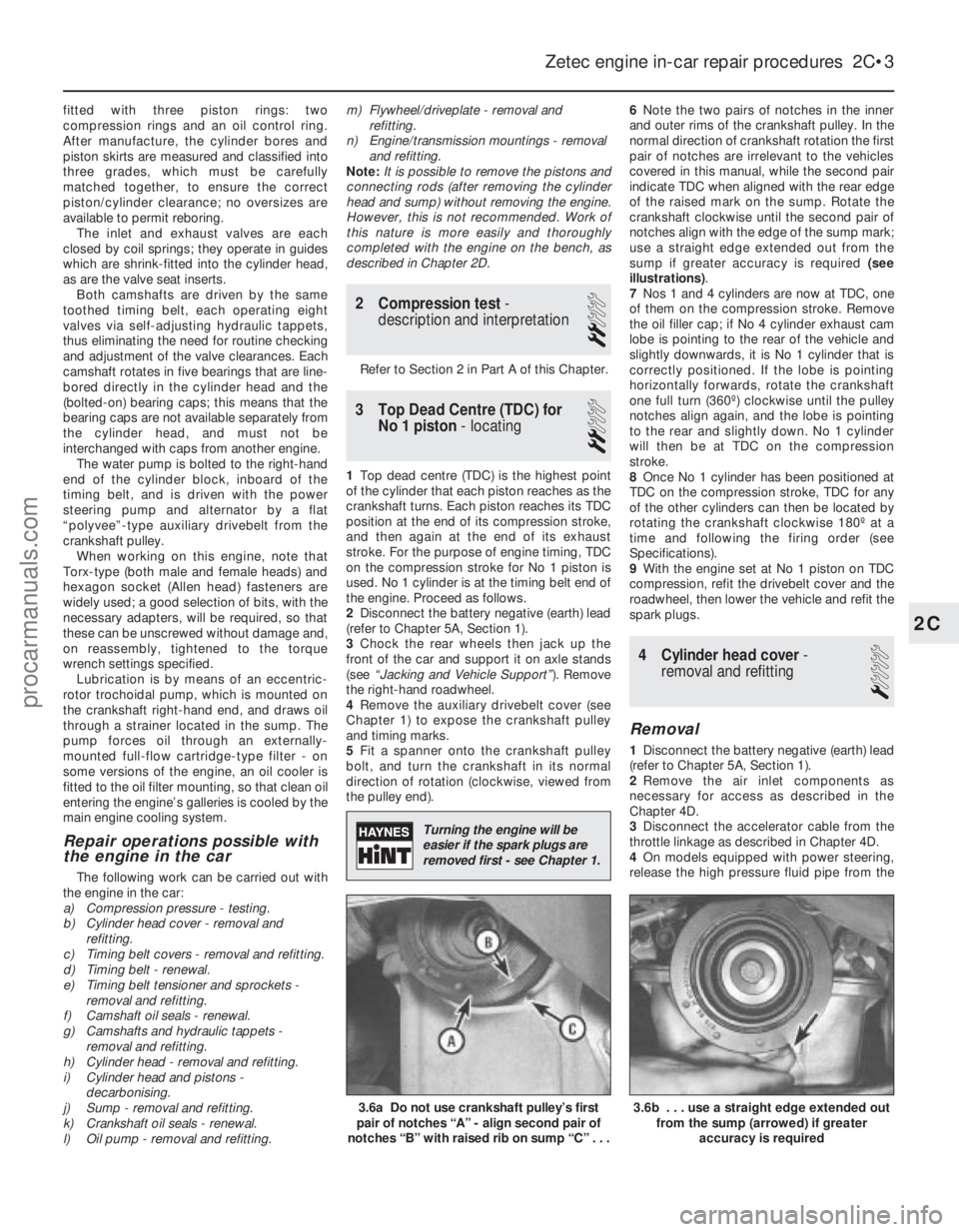
Note the two pairs of notches in the inner
and outer rims of the crankshaft pulley. In the
normal direction of crankshaft rotation the first
pair of notches are irrelevant to the vehicles
covered in this manual, while the second pair
indicate TDC when aligned with the rear edge
of the raised mark on the sump. Rotate the
crankshaft clockwise until the second pair of
notches align with the edge of the sump mark;
use a straight edge extended out from the
sump if greater accuracy is required (see
illustrations) .
7 Nos 1 and 4 cylinders are now at TDC, one
of them on the compression stroke. Remove
the oil filler cap; if No 4 cylinder exhaust cam
lobe is pointing to the rear of the vehicle and
slightly downwards, it is No 1 cylinder that is
correctly positioned. If the lobe is pointing
horizontally forwards, rotate the crankshaft
one full turn (360º) clockwise until the pulley
notches align again, and the lobe is pointing
to the rear and slightly down. No 1 cylinder
will then be at TDC on the compression
stroke.
8 Once No 1 cylinder has been positioned at
TDC on the compression stroke, TDC for any
of the other cylinders can then be located by
rotating the crankshaft clockwise 180º at a
time and following the firing order (see
Specifications).
9 With the engine set at No 1 piston on TDC
compression, refit the drivebelt cover and the
roadwheel, then lower the vehicle and refit the
spark plugs.
4 Cylinder head cover -
removal and refitting
1
Removal
1 Disconnect the battery negative (earth) lead
(refer to Chapter 5A, Section 1).
2 Remove the air inlet components as
necessary for access as described in the
Chapter 4D.
3 Disconnect the accelerator cable from the
throttle linkage as described in Chapter 4D.
4 On models equipped with power steering,
release the high pressure fluid pipe from the
Zetec engine in-car repair procedures 2C•3
3.6b . . . use a straight edge extended out from the sump (arrowed) if greater
accuracy is required3.6a Do not use crankshaft pulley’s first
pair of notches “A” - align second pair of
notches “B” with raised rib on sump “C” . . .
2C
1595Ford Fiesta Remake
Turning the engine will be
easier if the spark plugs are
removed first - see Chapter 1.
procarmanuals.com
http://vnx.su
Page 211 of 296

Front wheel toe setting -
checking and adjustment
2Due to the special measuring equipment
necessary to accurately check the wheel
alignment, and the skill required to use it
properly, checking and adjustment is best left
to a Ford dealer or similar expert. Note that
most tyre-fitting shops now possess
sophisticated checking equipment. The
following is provided as a guide, should the
owner decide to carry out a DIY check.
3 The front wheel toe setting is checked by
measuring the distance between the front and
rear inside edges of the roadwheel rims.
Proprietary toe measurement gauges are
available from motor accessory shops.
Adjustment is made by screwing the track
rods in or out of their track rod end balljoints,
to alter the effective length of the track rod
assemblies.
4 For accurate checking, the vehicle must
be at the kerb weight, ie unladen and with a
full tank of fuel.
5 Before starting work, check the tyre
pressures and tread wear, the condition of the
hub bearings, the steering wheel free play,
and the condition of the front suspension
components (see Chapter 1). Correct any
faults found.
6 Park the vehicle on level ground, check that
the front roadwheels are in the straight-ahead
position, then rock the rear and front ends to settle the suspension. Release the handbrake,
and roll the vehicle backwards 1 metre, then
forwards again, to relieve any stresses in the
steering and suspension components.
7
Measure the distance between the front
edges of the wheel rims and the rear edges of
the rims. Subtract the smallest measurement
from the largest, and check that the result is
within the specified range.
8 If adjustment is necessary, apply the
handbrake, then jack up the front of the
vehicle and support it securely on axle stands
(see “Jacking and Vehicle Support” ). Turn the
steering wheel onto full-left lock, and record
the number of exposed threads on the right-
hand track rod. Now turn the steering onto
full-right lock, and record the number of
threads on the left-hand side. If there are the
same number of threads visible on both sides,
then subsequent adjustment should be made
equally on both sides. If there are more
threads visible on one side than the other, it
will be necessary to compensate for this
during adjustment. Note:It is most important
that after adjustment, the same number of
threads are visible on each track rod.
9 First clean the track rod end; if they are
corroded, apply penetrating fluid before
starting adjustment. Release the rubber gaiter
outboard clips (where necessary), and peel
back the gaiter; apply a smear of grease to
the inside of the gaiter, so that both are free, and will not be twisted or strained as their
respective track rods are rotated.
10
Use a straight-edge and a scriber or
similar to mark the relationship of each track
rod to its track rod end balljoint, then, holding
each track rod in turn, unscrew its locknut
fully.
11 Alter the length of the track rods, bearing
in mind the note made in paragraph 8. Screw
them into or out of the track rod end balljoints,
rotating the track rods using a self-grip
wrench. Shortening the track rods (screwing
them into their track rod end balljoints) will
reduce toe-in/increase toe-out.
12 When the setting is correct, hold the track
rods and securely tighten the track rod end
balljoint locknuts. Count the exposed threads
to check the length of both track rods. If they
are not the same, then the adjustment has not
been made equally, and problems will be
encountered with tyre scrubbing in turns;
also, the steering wheel spokes will no longer
be horizontal when the wheels are in the
straight-ahead position.
13 If the track rod lengths are the same, lower
the vehicle to the ground and re-check the
toe setting; re-adjust if necessary. When the
setting is correct, securely tighten the track rod
end balljoint locknuts. Ensure that the rubber
gaiters are seated correctly, and are not
twisted or strained, and secure them in position
with new retaining clips (where necessary).
10•18 Suspension and steering
1595Ford Fiesta Remakeprocarmanuals.com
http://vnx.su
Page 227 of 296

suitable adhesive; it is recommended that this
task be left to a Ford dealer or similar expert.
15To remove the window glass, remove their
retaining screws and withdraw the lock
assemblies, slide the front glass as far to the
rear as possible, then prise up and withdraw
the front glass guide; it will be necessary to
pull the last part of the guide from under the
glass.
16 Withdraw the vertical seal and two
support blocks from between the two glasses,
slide the seal to the front of the frame, and
withdraw it. Slide each glass in turn
to the front of the frame and withdraw it,
then prise up and withdraw the rear glass
guide.
Refitting
17 On refitting, check that the glass guides
are undamaged; renew them if necessary.
Ensure that the lock assemblies are removed
from both glasses.
18 Press the rear glass guide into place. Refit
first the rear glass, fitting it to the front of the
frame and sliding it to the rear, then the front
glass, in the same way.
19 To refit the vertical seal, sandwich it
between two strips of thin sheet metal and
install it, with its support blocks, first in the
front part of the frame, then push it into place.
This will require some effort as the glass is
reached, due to the distortion caused by the
location notch on the block. When the seal is
fully in place, withdraw the metal strips, and
check that the seal’s lips have not folded back
on themselves.
20 When refitting the front glass guide, locate
it first around the frame’s detent catch, then
slide it under the glass using soapy water as a
lubricant.
21 Refit the lock assemblies, clean the
glasses, and check the operation of the
windows and locks.
34 Windscreen and tailgate window glass -
removal and refitting
4
Note : The DIY mechanic is advised to leave
windscreen/tailgate window glass removal
and refitting to an expert. For those with the
necessary tools and equipment, the
following paragraphs are a guide to the
procedure.
Removal
1 Remove the windscreen/tailgate wiper arms
as described in Chapter 12.
2 If removing the windscreen, remove both A-
pillar trims, and release the front of the
headlining by removing the sun visors and
courtesy light. If a heated windscreen is fitted,
disconnect its electrical contacts at the
windscreen. If removing the tailgate window
glass, disconnect the wiring to the heating
element. 3
As a precautionary measure to prevent
damage to the paintwork, cover the
surrounding bodywork with an old blanket or
similar.
4 Using a suitable tool, release the
weatherseal from the top and sides of the
body aperture flange before exerting pressure
from the inside of the vehicle to remove the
assembly. It is strongly advised that an
assistant outside the vehicle is ready to
receive the glass as it is pushed out.
5 With the assembly removed from the
vehicle, detach the weatherseal from the
windscreen/tailgate glass.
Refitting
6 With reference to the procedures described
for the fixed side window glass in Section 33,
clean the weatherseal, then refit in
accordance with the rest of that Section.
7 Any trim and equipment removed during
preparation should now be refitted.
35 Sunroof panel -
removal and refitting
1
Removal
1 Open the sunroof fully using the handwheel.
2 Detach the sunroof from its rearward
mounting point by pressing in the red locking
bar on the handwheel, then raise it and
remove.
Refitting
3 To refit, engage the hinges in their
locations, in the forward edge of the sunroof
opening, then lower the sunroof. Allow the
handwheel to click into its safety lock.
4 Check that the safety lock mechanism
retains the panel securely.
5 Close the sunroof fully using the
handwheel.
36 Sunroof panel seal -
renewal
1
1 Remove the sunroof panel, as described in
Section 35, then lay the panel on a soft cloth.
2 Remove the two hinge plate assemblies
from the panel by undoing the hinge plate
retaining screws.
3 Pull the seal from the panel edge, noting the
position of its join.
4 Starting from the position of the original
join, press the seal into position, ensuring that
it sits evenly right around. Adjust as necessary
so that the ends butt tightly together.
5 Refit the two hinge plate assemblies to the
panel.
6 Refit the sunroof panel, as described in
Section 35.
37 Sunroof weatherseal -
removal and refitting
1
Removal
1 Remove the sunroof panel, as described in
Section 35.
2 Starting from the joint on the rearward
opening edge, pull the seal up and remove.
Refitting
3 Refitting is a reversal of the removal
procedure, ensuring that the weatherseal
does not deform at the corners, or split at the
joint.
38 Full-length sunroof -
general information
1 The full-length sunroof is electrically-
operated, the operating system consisting of
the motor and the roof-mounted switch. The
circuit is fed via fuses 18 and 28 from the
ignition switch; switch illumination is via
fuse 6.
2 All components are mounted in the roof of
the passenger compartment, above the
headlining at the front of the vehicle.
3 To open the sunroof, press the switch
lightly on the upper side; to close it, check
first that the opening is completely
unobstructed, and press the switch on the
lower side.
4 Maintenance is confined to checking for
freedom of action and a snug fit when shut.
Check that the seals are in good clean
condition and not scratched or damaged.
5 Owners must note the following to ensure
that the maximum trouble-free life from this
feature:
a) It is normal for the motor to slow down as
the sunroof approaches full opening.
b) If the sunroof stops before it is fully
opened in cold weather, this may be due
to the material being too hard to fold
correctly; do not force the sunroof open if
this is suspected.
c) If the material does not fold correctly on
opening at any time, close the sunroof
again, correct the folds by hand, and try
again.
d) Never open or close the sunroof with the
vehicle travelling at more than 70 mph
(120 km/h), and never allow passengers to
travel standing up or with any part of their
bodies in the opening.
e) Ensure that any collected water, snow or ice is removed from the sunroof before
opening it. Check that the deflector is
clear of water, particularly after washing
the vehicle; sponge it dry if necessary.
f) Never place heavy objects on the sunroof or its surrounds.
g) The sunroof should be cleaned frequently
11•16 Bodywork and fittings
1595Ford Fiesta Remakeprocarmanuals.com
http://vnx.su