1989 FORD FIESTA water pump
[x] Cancel search: water pumpPage 12 of 296
4 Auxiliary drivebelt check andrenewal
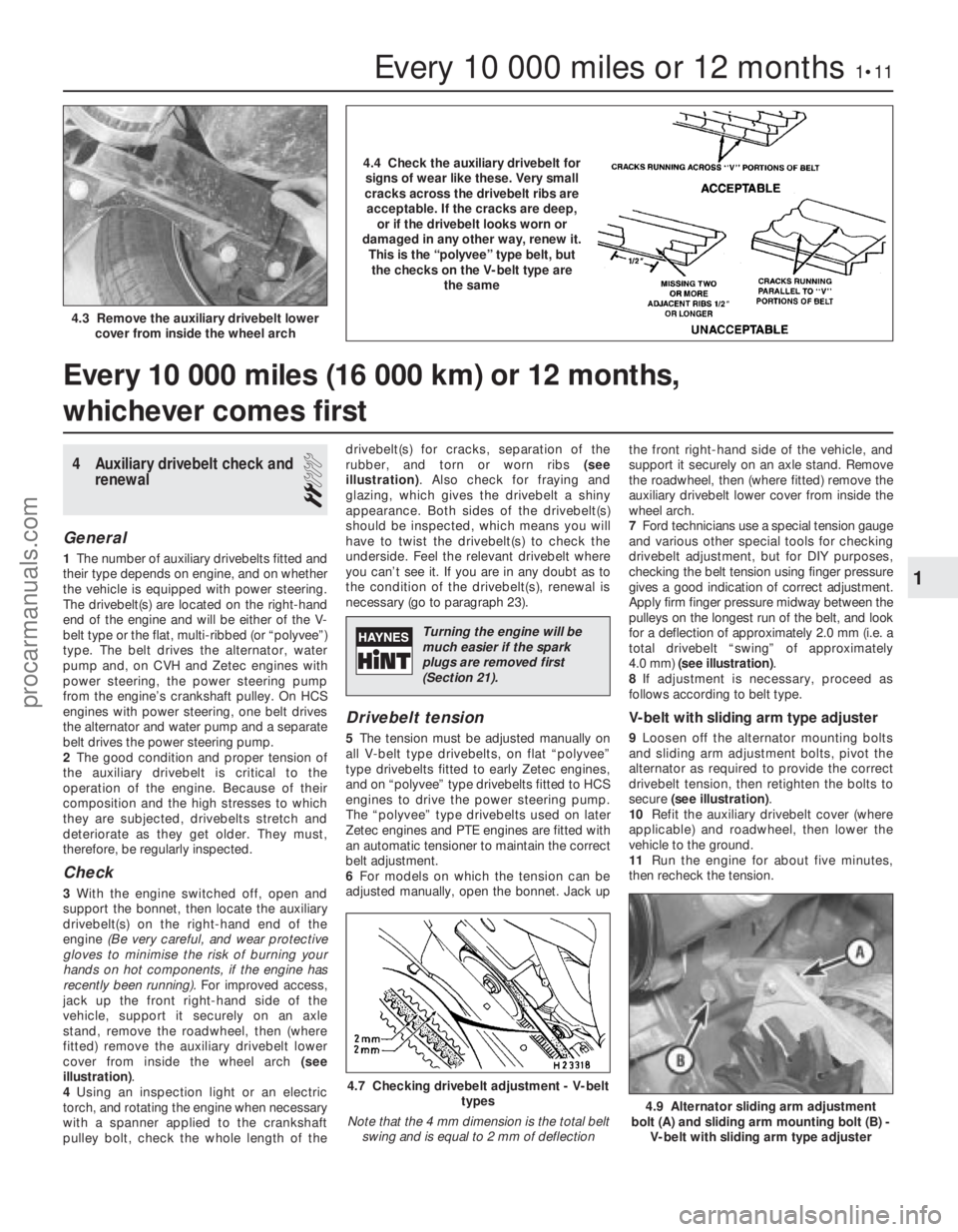
2
General
1The number of auxiliary drivebelts fitted and
their type depends on engine, and on whether
the vehicle is equipped with power steering.
The drivebelt(s) are located on the right-hand
end of the engine and will be either of the V-
belt type or the flat, multi-ribbed (or “polyvee”)
type. The belt drives the alternator, water
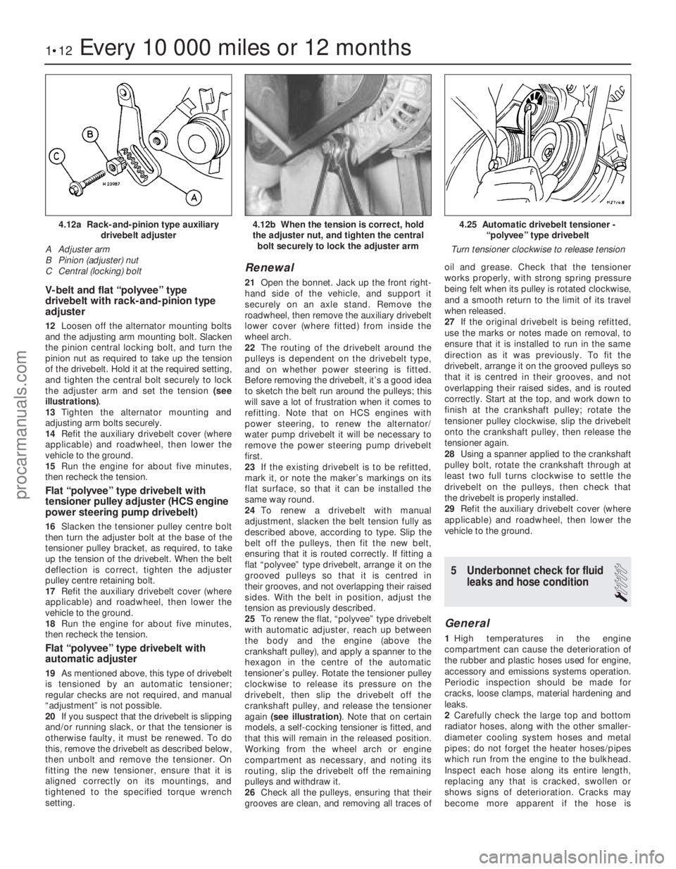
pump and, on CVH and Zetec engines with
power steering, the power steering pump
from the engine’s crankshaft pulley. On HCS
engines with power steering, one belt drives
the alternator and water pump and a separate
belt drives the power steering pump.
2 The good condition and proper tension of
the auxiliary drivebelt is critical to the
operation of the engine. Because of their
composition and the high stresses to which
they are subjected, drivebelts stretch and
deteriorate as they get older. They must,
therefore, be regularly inspected.
Check
3 With the engine switched off, open and
support the bonnet, then locate the auxiliary
drivebelt(s) on the right-hand end of the
engine (Be very careful, and wear protective
gloves to minimise the risk of burning your
hands on hot components, if the engine has
recently been running). For improved access,
jack up the front right-hand side of the
vehicle, support it securely on an axle
stand, remove the roadwheel, then (where
fitted) remove the auxiliary drivebelt lower
cover from inside the wheel arch (see
illustration) .
4 Using an inspection light or an electric
torch, and rotating the engine when necessary
with a spanner applied to the crankshaft
pulley bolt, check the whole length of the drivebelt(s) for cracks, separation of the
rubber, and torn or worn ribs
(see
illustration) . Also check for fraying and
glazing, which gives the drivebelt a shiny
appearance. Both sides of the drivebelt(s)
should be inspected, which means you will
have to twist the drivebelt(s) to check the
underside. Feel the relevant drivebelt where
you can’t see it. If you are in any doubt as to
the condition of the drivebelt(s), renewal is
necessary (go to paragraph 23).
Drivebelt tension
5 The tension must be adjusted manually on
all V-belt type drivebelts, on flat “polyvee”
type drivebelts fitted to early Zetec engines,
and on “polyvee” type drivebelts fitted to HCS
engines to drive the power steering pump.
The “polyvee” type drivebelts used on later
Zetec engines and PTE engines are fitted with
an automatic tensioner to maintain the correct
belt adjustment.
6 For models on which the tension can be
adjusted manually, open the bonnet. Jack up the front right-hand side of the vehicle, and
support it securely on an axle stand. Remove
the roadwheel, then (where fitted) remove the
auxiliary drivebelt lower cover from inside the
wheel arch.
7
Ford technicians use a special tension gauge
and various other special tools for checking
drivebelt adjustment, but for DIY purposes,
checking the belt tension using finger pressure
gives a good indication of correct adjustment.
Apply firm finger pressure midway between the
pulleys on the longest run of the belt, and look
for a deflection of approximately 2.0 mm (i.e. a
total drivebelt “swing” of approximately
4.0 mm) (see illustration) .
8 If adjustment is necessary, proceed as
follows according to belt type.
V-belt with sliding arm type adjuster
9 Loosen off the alternator mounting bolts
and sliding arm adjustment bolts, pivot the
alternator as required to provide the correct
drivebelt tension, then retighten the bolts to
secure (see illustration) .
10 Refit the auxiliary drivebelt cover (where
applicable) and roadwheel, then lower the
vehicle to the ground.
11 Run the engine for about five minutes,
then recheck the tension.
Every 10 000 miles (16 000 km) or 12 months,
whichever comes first
Every 10 000 miles or 12 months1•11
4.9 Alternator sliding arm adjustment
bolt (A) and sliding arm mounting bolt (B) - V-belt with sliding arm type adjuster
4.7 Checking drivebelt adjustment - V-belt types
Note that the 4 mm dimension is the total belt swing and is equal to 2 mm of deflection
4.3 Remove the auxiliary drivebelt lower cover from inside the wheel arch
1
1595Ford Fiesta Remake
4.4 Check the auxiliary drivebelt forsigns of wear like these. Very small
cracks across the drivebelt ribs are acceptable. If the cracks are deep, or if the drivebelt looks worn or
damaged in any other way, renew it. This is the “polyvee” type belt, butthe checks on the V-belt type are the same
Turning the engine will be
much easier if the spark
plugs are removed first
(Section 21).
procarmanuals.com
http://vnx.su
Page 13 of 296
V-belt and flat “polyvee” type
drivebelt with rack-and-pinion type
adjuster
12Loosen off the alternator mounting bolts
and the adjusting arm mounting bolt. Slacken
the pinion central locking bolt, and turn the
pinion nut as required to take up the tension
of the drivebelt. Hold it at the required setting,
and tighten the central bolt securely to lock
the adjuster arm and set the tension (see
illustrations) .
13 Tighten the alternator mounting and
adjusting arm bolts securely.
14 Refit the auxiliary drivebelt cover (where
applicable) and roadwheel, then lower the
vehicle to the ground.
15 Run the engine for about five minutes,
then recheck the tension.
Flat “polyvee” type drivebelt with
tensioner pulley adjuster (HCS engine
power steering pump drivebelt)
16 Slacken the tensioner pulley centre bolt
then turn the adjuster bolt at the base of the
tensioner pulley bracket, as required, to take
up the tension of the drivebelt. When the belt
deflection is correct, tighten the adjuster
pulley centre retaining bolt.
17 Refit the auxiliary drivebelt cover (where
applicable) and roadwheel, then lower the
vehicle to the ground.
18 Run the engine for about five minutes,
then recheck the tension.
Flat “polyvee” type drivebelt with
automatic adjuster
19 As mentioned above, this type of drivebelt
is tensioned by an automatic tensioner;
regular checks are not required, and manual
“adjustment” is not possible.
20 If you suspect that the drivebelt is slipping
and/or running slack, or that the tensioner is
otherwise faulty, it must be renewed. To do
this, remove the drivebelt as described below,
then unbolt and remove the tensioner. On
fitting the new tensioner, ensure that it is
aligned correctly on its mountings, and
tightened to the specified torque wrench
setting.
Renewal
21 Open the bonnet. Jack up the front right-
hand side of the vehicle, and support it
securely on an axle stand. Remove the
roadwheel, then remove the auxiliary drivebelt
lower cover (where fitted) from inside the
wheel arch.
22 The routing of the drivebelt around the
pulleys is dependent on the drivebelt type,
and on whether power steering is fitted.
Before removing the drivebelt, it’s a good idea
to sketch the belt run around the pulleys; this
will save a lot of frustration when it comes to
refitting. Note that on HCS engines with
power steering, to renew the alternator/
water pump drivebelt it will be necessary to
remove the power steering pump drivebelt
first.
23 If the existing drivebelt is to be refitted,
mark it, or note the maker’s markings on its
flat surface, so that it can be installed the
same way round.
24 To renew a drivebelt with manual
adjustment, slacken the belt tension fully as
described above, according to type. Slip the
belt off the pulleys, then fit the new belt,
ensuring that it is routed correctly. If fitting a
flat “polyvee” type drivebelt, arrange it on the
grooved pulleys so that it is centred in
their grooves, and not overlapping their raised
sides. With the belt in position, adjust the
tension as previously described.
25 To renew the flat, “polyvee” type drivebelt
with automatic adjuster, reach up between
the body and the engine (above the
crankshaft pulley), and apply a spanner to the
hexagon in the centre of the automatic
tensioner’s pulley. Rotate the tensioner pulley
clockwise to release its pressure on the
drivebelt, then slip the drivebelt off the
crankshaft pulley, and release the tensioner
again (see illustration) . Note that on certain
models, a self-cocking tensioner is fitted, and
that this will remain in the released position.
Working from the wheel arch or engine
compartment as necessary, and noting its
routing, slip the drivebelt off the remaining
pulleys and withdraw it.
26 Check all the pulleys, ensuring that their
grooves are clean, and removing all traces of oil and grease. Check that the tensioner
works properly, with strong spring pressure
being felt when its pulley is rotated clockwise,
and a smooth return to the limit of its travel
when released.
27
If the original drivebelt is being refitted,
use the marks or notes made on removal, to
ensure that it is installed to run in the same
direction as it was previously. To fit the
drivebelt, arrange it on the grooved pulleys so
that it is centred in their grooves, and not
overlapping their raised sides, and is routed
correctly. Start at the top, and work down to
finish at the crankshaft pulley; rotate the
tensioner pulley clockwise, slip the drivebelt
onto the crankshaft pulley, then release the
tensioner again.
28 Using a spanner applied to the crankshaft
pulley bolt, rotate the crankshaft through at
least two full turns clockwise to settle the
drivebelt on the pulleys, then check that
the drivebelt is properly installed.
29 Refit the auxiliary drivebelt cover (where
applicable) and roadwheel, then lower the
vehicle to the ground.
5 Underbonnet check for fluid leaks and hose condition
1
General
1High temperatures in the engine
compartment can cause the deterioration of
the rubber and plastic hoses used for engine,
accessory and emissions systems operation.
Periodic inspection should be made for
cracks, loose clamps, material hardening and
leaks.
2 Carefully check the large top and bottom
radiator hoses, along with the other smaller-
diameter cooling system hoses and metal
pipes; do not forget the heater hoses/pipes
which run from the engine to the bulkhead.
Inspect each hose along its entire length,
replacing any that is cracked, swollen or
shows signs of deterioration. Cracks may
become more apparent if the hose is
1•12Every 10 000 miles or 12 months
4.25 Automatic drivebelt tensioner - “polyvee” type drivebelt
Turn tensioner clockwise to release tension4.12b When the tension is correct, hold
the adjuster nut, and tighten the central bolt securely to lock the adjuster arm4.12a Rack-and-pinion type auxiliary drivebelt adjuster
A Adjuster arm
B Pinion (adjuster) nut
C Central (locking) bolt
1595Ford Fiesta Remakeprocarmanuals.com
http://vnx.su
Page 26 of 296
the specified type of fluid. It is essential that
no dirt is introduced into the transmission
during this operation.
7Depending on the extent to which the fluid
was allowed to drain, it is possible that the
amount of fluid required when filling the
transmission may be more than the specified
amount (see “Lubricants, fluids and tyre
pressures” ). However, due to fluid remaining in
the system, it is more likely that less than the
specified amount will be required. Add about
half the specified amount, then run the engine
up to its normal operating temperature and
check the level on the dipstick. When the level
approaches the maximum mark, proceed as
detailed in Section 20 to check the level and
complete the final topping-up as described.
27 Handbrake adjustment
3
1 Chock the front wheels then jack up the
rear of the car and support it on axle stands
(see “Jacking and Vehicle Support” ). Fully
release the handbrake.
2 Check that the handbrake cables are
correctly routed and secured by the retaining
clips at the appropriate points under the vehicle.
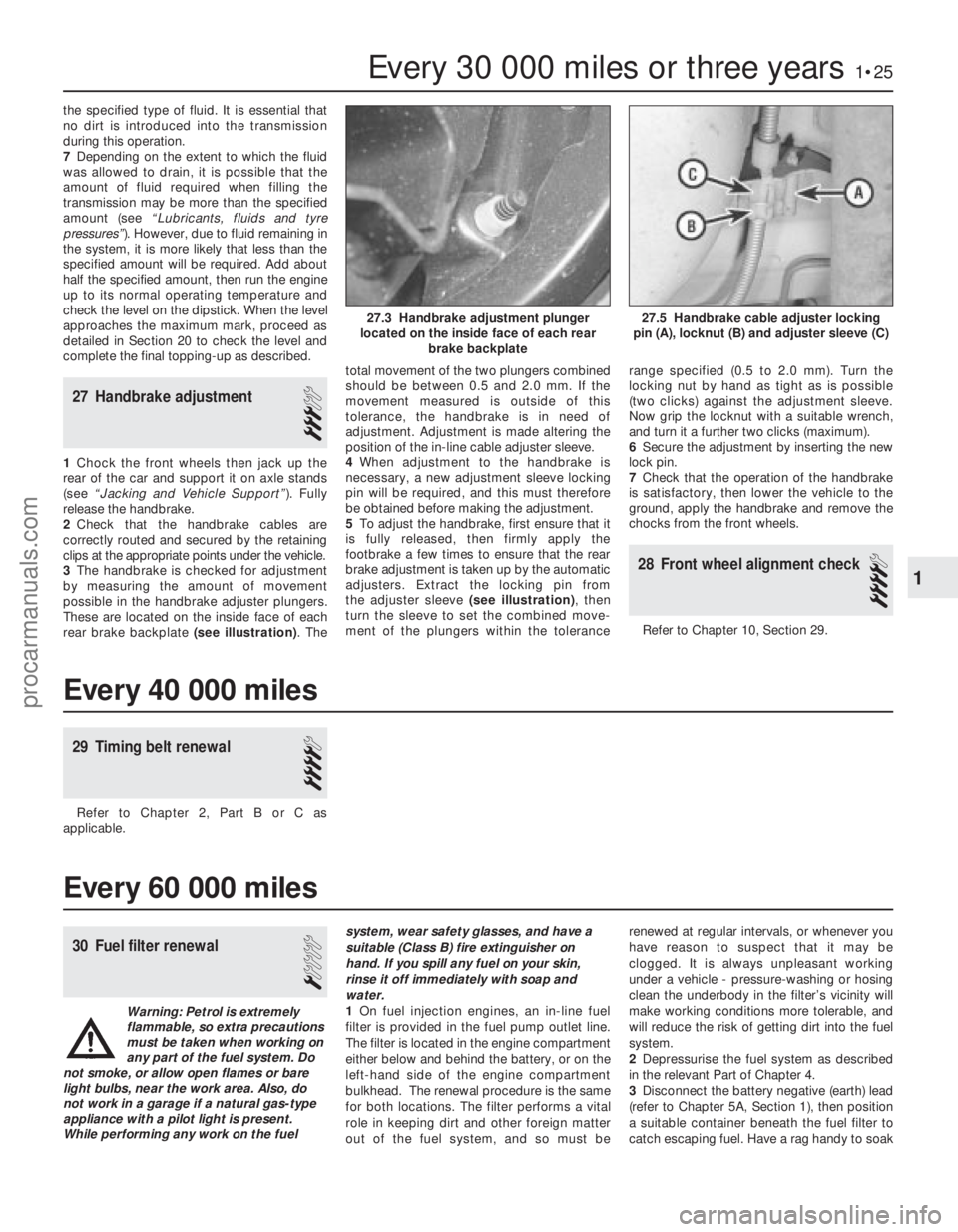
3 The handbrake is checked for adjustment
by measuring the amount of movement
possible in the handbrake adjuster plungers.
These are located on the inside face of each
rear brake backplate (see illustration) . Thetotal movement of the two plungers combined
should be between 0.5 and 2.0 mm. If the
movement measured is outside of this
tolerance, the handbrake is in need of
adjustment. Adjustment is made altering the
position of the in-line cable adjuster sleeve.
4
When adjustment to the handbrake is
necessary, a new adjustment sleeve locking
pin will be required, and this must therefore
be obtained before making the adjustment.
5 To adjust the handbrake, first ensure that it
is fully released, then firmly apply the
footbrake a few times to ensure that the rear
brake adjustment is taken up by the automatic
adjusters. Extract the locking pin from
the adjuster sleeve (see illustration), then
turn the sleeve to set the combined move-
ment of the plungers within the tolerance range specified (0.5 to 2.0 mm). Turn the
locking nut by hand as tight as is possible
(two clicks) against the adjustment sleeve.
Now grip the locknut with a suitable wrench,
and turn it a further two clicks (maximum).
6
Secure the adjustment by inserting the new
lock pin.
7 Check that the operation of the handbrake
is satisfactory, then lower the vehicle to the
ground, apply the handbrake and remove the
chocks from the front wheels.
28 Front wheel alignment check
4
Refer to Chapter 10, Section 29.
Every 30 000 miles or three years1•25
27.5 Handbrake cable adjuster locking
pin (A), locknut (B) and adjuster sleeve (C)27.3 Handbrake adjustment plunger
located on the inside face of each rear brake backplate
1
1595Ford Fiesta Remake
Every 40 000 miles
29 Timing belt renewal
4
Refer to Chapter 2, Part B or C as
applicable.
Every 60 000 miles
30 Fuel filter renewal
1
Warning: Petrol is extremely
flammable, so extra precautions
must be taken when working on
any part of the fuel system. Do
not smoke, or allow open flames or bare
light bulbs, near the work area. Also, do
not work in a garage if a natural gas-type appliance with a pilot light is present.
While performing any work on the fuel system, wear safety glasses, and have a
suitable (Class B) fire extinguisher on
hand. If you spill any fuel on your skin,
rinse it off immediately with soap and
water.
1
On fuel injection engines, an in-line fuel
filter is provided in the fuel pump outlet line.
The filter is located in the engine compartment
either below and behind the battery, or on the
left-hand side of the engine compartment
bulkhead. The renewal procedure is the same
for both locations. The filter performs a vital
role in keeping dirt and other foreign matter
out of the fuel system, and so must be renewed at regular intervals, or whenever you
have reason to suspect that it may be
clogged. It is always unpleasant working
under a vehicle - pressure-washing or hosing
clean the underbody in the filter’s vicinity will
make working conditions more tolerable, and
will reduce the risk of getting dirt into the fuel
system.
2
Depressurise the fuel system as described
in the relevant Part of Chapter 4.
3 Disconnect the battery negative (earth) lead
(refer to Chapter 5A, Section 1), then position
a suitable container beneath the fuel filter to
catch escaping fuel. Have a rag handy to soak
procarmanuals.com
http://vnx.su
Page 29 of 296
Lubrication
Engine oil type/specification . . . . . . . . . . . . . . . . . . . . . . . . . . . . . . . . . . See “Lubricants, fluids and tyre pressures”
Engine oil capacity . . . . . . . . . . . . . . . . . . . . . . . . . . . . . . . . . . . .\
. . . . . See “Lubricants, fluids and tyre pressures”
Oil pressure: At idle speed . . . . . . . . . . . . . . . . . . . . . . . . . . . . . . . . . . . .\
. . . . . . . . 0.60 barsAt 2000 rpm . . . . . . . . . . . . . . . . . . . . . . . . . . . . . . . . . . . .\
. . . . . . . . 1.50 bars
Oil pump clearances: Outer rotor-to-body . . . . . . . . . . . . . . . . . . . . . . . . . . . . . . . . . . . .\
. . 0.14 to 0.26 mm
Inner rotor-to-outer rotor . . . . . . . . . . . . . . . . . . . . . . . . . . . . . . . . . . 0.051 to 0.127 mm
Rotor endfloat . . . . . . . . . . . . . . . . . . . . . . . . . . . . . . . . . . . .\
. . . . . . . 0.025 to 0.06 mm
Torque wrench settingsNm lbf ft
Camshaft thrust plate bolts . . . . . . . . . . . . . . . . . . . . . . . . . . . . . . . . . . 5 4
Camshaft sprocket bolt . . . . . . . . . . . . . . . . . . . . . . . . . . . . . . . . . . . .\
. 1813
Crankshaft pulley bolt . . . . . . . . . . . . . . . . . . . . . . . . . . . . . . . . . . . .\
. . . 115 85
Rocker shaft pedestal bolts . . . . . . . . . . . . . . . . . . . . . . . . . . . . . . . . . . 4332
Flywheel bolts . . . . . . . . . . . . . . . . . . . . . . . . . . . . . . . . . . . .\
. . . . . . . . . 6749
Sump: Stage 1 . . . . . . . . . . . . . . . . . . . . . . . . . . . . . . . . . . . .\
. . . . . . . . . . . . 7 5
Stage 2 . . . . . . . . . . . . . . . . . . . . . . . . . . . . . . . . . . . .\
. . . . . . . . . . . . 9 7
Stage 3 (with engine warm) . . . . . . . . . . . . . . . . . . . . . . . . . . . . . . . . 9 7
Oil pressure switch . . . . . . . . . . . . . . . . . . . . . . . . . . . . . . . . . . . .\
. . . . . 1410
Cylinder head bolts (may be re-used once only): Stage 1 . . . . . . . . . . . . . . . . . . . . . . . . . . . . . . . . . . . .\
. . . . . . . . . . . . 3022
Stage 2 . . . . . . . . . . . . . . . . . . . . . . . . . . . . . . . . . . . .\
. . . . . . . . . . . . Angle-tighten a further 90º
Stage 3 . . . . . . . . . . . . . . . . . . . . . . . . . . . . . . . . . . . .\
. . . . . . . . . . . . Angle-tighten a further 90º
Timing chain tensioner . . . . . . . . . . . . . . . . . . . . . . . . . . . . . . . . . . . .\
. . 8 6
Timing chain cover . . . . . . . . . . . . . . . . . . . . . . . . . . . . . . . . . . . .\
. . . . . 9 7
Crankshaft rear oil seal housing . . . . . . . . . . . . . . . . . . . . . . . . . . . . . . . 1813
Rocker cover bolts . . . . . . . . . . . . . . . . . . . . . . . . . . . . . . . . . . . .\
. . . . . 5 4
Oil pump . . . . . . . . . . . . . . . . . . . . . . . . . . . . . . . . . . . .\
. . . . . . . . . . . . . 1813
Oil pump cover . . . . . . . . . . . . . . . . . . . . . . . . . . . . . . . . . . . .\
. . . . . . . . 9 7
Engine mountings: Engine mounting (right-hand):Bolt to body (in wheel arch) . . . . . . . . . . . . . . . . . . . . . . . . . . . . . . 41 to 58 30 to 43
Nut to body (by suspension strut) . . . . . . . . . . . . . . . . . . . . . . . . . . 41 to 58 30 to 43
Bracket to cylinder block . . . . . . . . . . . . . . . . . . . . . . . . . . . . . . . . 54 to 72 40 to 53
Rubber insulator to bracket . . . . . . . . . . . . . . . . . . . . . . . . . . . . . . 71 to 95 52 to 70
Transmission mounting fasteners . . . . . . . . . . . . . . . . . . . . . . . . . . . . Refer to Chapter 7A or 7B
Note: Refer to Part D of this Chapter for remaining torque wrench settings.
2A•2 HCS engine in-car repair procedures
1595Ford Fiesta Remake
1 General information
How to use this Chapter
This Part of Chapter 2 is devoted to repair
procedures possible while the engine is still
installed in the vehicle, and includes only the
Specifications relevant to those procedures.
Similar information concerning the 1.4 and
1.6 litre CVH and PTE engines, and the 1.6
and 1.8 litre Zetec engines, will be found in
Parts B and C of this Chapter respectively.
Since these procedures are based on the
assumption that the engine is installed in the
vehicle, if the engine has been removed from
the vehicle and mounted on a stand, some
of the preliminary dismantling steps outlined
will not apply. Information concerning engine/transmission
removal and refitting, and engine overhaul, can
be found in Part D of this Chapter, which also
includes the Specifications relevant to those
procedures.
Engine description
The engine is an overhead valve, water-
cooled, four cylinder in-line design,
designated HCS (High Compression Swirl).
The engine is mounted transversely at the
front of the vehicle together with the
transmission to form a combined power unit. The crankshaft is supported in three or five
shell-type main bearings. The connecting rod
big-end bearings are also split shell-type, and
are attached to the pistons by interference-fit
gudgeon pins. Each piston is fitted with two
compression rings and one oil control ring. The camshaft, which runs on bearings
within the cylinder block, is chain-driven from
the crankshaft, and operates the valves via
pushrods and rocker arms. The valves are
each closed by a single valve spring, and
operate in guides integral in the cylinder head. The oil pump is mounted externally on the
crankcase, incorporates a full-flow oil filter,
and is driven by a skew gear on the camshaft.
On carburettor versions, the fuel pump is also
driven from the camshaft, via an eccentric
lobe.
Repair operations possible with
the engine in the car
The following work can be carried out with
the engine in the car:
a) Compression pressure - testing.
b) Cylinder head rocker cover - removal
and refitting.
c) Valve clearances - adjustment.
d) Rocker shaft assembly - removal,
inspection and refitting.
e) Cylinder head - removal and refitting
f) Cylinder head and pistons - decarbonising.
g) Crankshaft pulley - removal and refitting.
h) Crankshaft oil seals - renewal.
i) Timing chain, sprockets and tensioner -
removal, inspection and refitting.
j) Oil filter renewal.
k) Oil pump - removal and refitting.
l) Sump - removal and refitting.
m) Flywheel - removal, inspection and
refitting.
n) Engine/transmission mountings -
inspection and renewal.
Note: It is possible to remove the pistons and
procarmanuals.com
http://vnx.su
Page 33 of 296
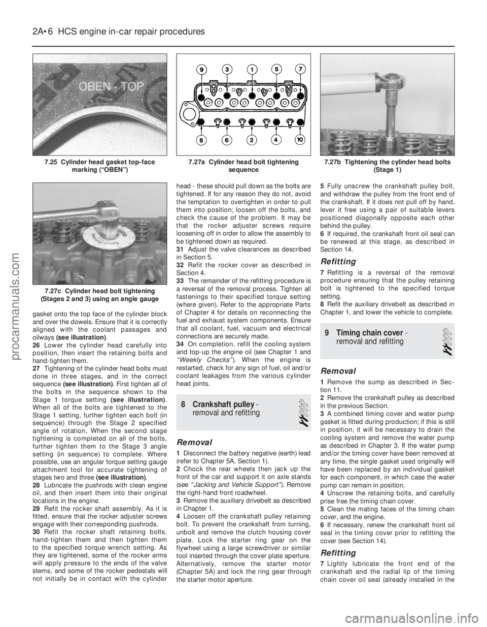
gasket onto the top face of the cylinder block
and over the dowels. Ensure that it is correctly
aligned with the coolant passages and
oilways (see illustration) .
26 Lower the cylinder head carefully into
position, then insert the retaining bolts and
hand-tighten them.
27 Tightening of the cylinder head bolts must
done in three stages, and in the correct
sequence (see illustration) . First tighten all of
the bolts in the sequence shown to the
Stage 1 torque setting (see illustration).
When all of the bolts are tightened to the
Stage 1 setting, further tighten each bolt (in
sequence) through the Stage 2 specified
angle of rotation. When the second stage
tightening is completed on all of the bolts,
further tighten them to the Stage 3 angle
setting (in sequence) to complete. Where
possible, use an angular torque setting gauge
attachment tool for accurate tightening of
stages two and three (see illustration).
28 Lubricate the pushrods with clean engine
oil, and then insert them into their original
locations in the engine.
29 Refit the rocker shaft assembly. As it is
fitted, ensure that the rocker adjuster screws
engage with their corresponding pushrods.
30 Refit the rocker shaft retaining bolts,
hand-tighten them and then tighten them
to the specified torque wrench setting. As
they are tightened, some of the rocker arms
will apply pressure to the ends of the valve
stems, and some of the rocker pedestals will
not initially be in contact with the cylinder head - these should pull down as the bolts are
tightened. If for any reason they do not, avoid
the temptation to overtighten in order to pull
them into position; loosen off the bolts, and
check the cause of the problem. It may be
that the rocker adjuster screws require
loosening off in order to allow the assembly to
be tightened down as required.
31
Adjust the valve clearances as described
in Section 5.
32 Refit the rocker cover as described in
Section 4.
33 The remainder of the refitting procedure is
a reversal of the removal process. Tighten all
fastenings to their specified torque setting
(where given). Refer to the appropriate Parts
of Chapter 4 for details on reconnecting the
fuel and exhaust system components. Ensure
that all coolant, fuel, vacuum and electrical
connections are securely made.
34 On completion, refill the cooling system
and top-up the engine oil (see Chapter 1 and
“Weekly Checks” ). When the engine is
restarted, check for any sign of fuel, oil and/or
coolant leakages from the various cylinder
head joints.
8 Crankshaft pulley -
removal and refitting
2
Removal
1 Disconnect the battery negative (earth) lead
(refer to Chapter 5A, Section 1).
2 Chock the rear wheels then jack up the
front of the car and support it on axle stands
(see “Jacking and Vehicle Support” ). Remove
the right-hand front roadwheel.
3 Remove the auxiliary drivebelt as described
in Chapter 1.
4 Loosen off the crankshaft pulley retaining
bolt. To prevent the crankshaft from turning,
unbolt and remove the clutch housing cover
plate. Lock the starter ring gear on the
flywheel using a large screwdriver or similar
tool inserted through the cover plate aperture.
Alternatively, remove the starter motor
(Chapter 5A) and lock the ring gear through
the starter motor aperture. 5
Fully unscrew the crankshaft pulley bolt,
and withdraw the pulley from the front end of
the crankshaft. If it does not pull off by hand,
lever it free using a pair of suitable levers
positioned diagonally opposite each other
behind the pulley.
6 If required, the crankshaft front oil seal can
be renewed at this stage, as described in
Section 14.
Refitting
7 Refitting is a reversal of the removal
procedure ensuring that the pulley retaining
bolt is tightened to the specified torque
setting.
8 Refit the auxiliary drivebelt as described in
Chapter 1, and lower the vehicle to complete.
9 Timing chain cover -
removal and refitting
2
Removal
1 Remove the sump as described in Sec-
tion 11.
2 Remove the crankshaft pulley as described
in the previous Section.
3 A combined timing cover and water pump
gasket is fitted during production; if this is still
in position, it will be necessary to drain the
cooling system and remove the water pump
as described in Chapter 3. If the water pump
and/or the timing cover have been removed at
any time, the single gasket used originally will
have been replaced by an individual gasket
for each component, in which case the water
pump can remain in position.
4 Unscrew the retaining bolts, and carefully
prise free the timing chain cover.
5 Clean the mating faces of the timing chain
cover, and the engine.
6 If necessary, renew the crankshaft front oil
seal in the timing cover prior to refitting the
cover (see Section 14).
Refitting
7 Lightly lubricate the front end of the
crankshaft and the radial lip of the timing
chain cover oil seal (already installed in the
2A•6 HCS engine in-car repair procedures
7.27c Cylinder head bolt tightening
(Stages 2 and 3) using an angle gauge
7.27b Tightening the cylinder head bolts (Stage 1)7.27a Cylinder head bolt tighteningsequence7.25 Cylinder head gasket top-facemarking (“OBEN”)
1595Ford Fiesta Remakeprocarmanuals.com
http://vnx.su
Page 34 of 296
cover). Using a new gasket, fit the timing
chain cover, centring it with the aid of the
crankshaft pulley - lubricate the seal contact
surfaces beforehand. Refit and tighten the
retaining bolts but, where applicable, leave
out the timing cover bolt which also secures
the water pump at this stage.
8Where applicable, refit the water pump as
described in Chapter 3.
9 Refit the crankshaft pulley as described in
the previous Section.
10 Refit the sump as described in Section 11.
10Timing chain, sprockets and
tensioner - removal,
inspection and refitting
3
Removal
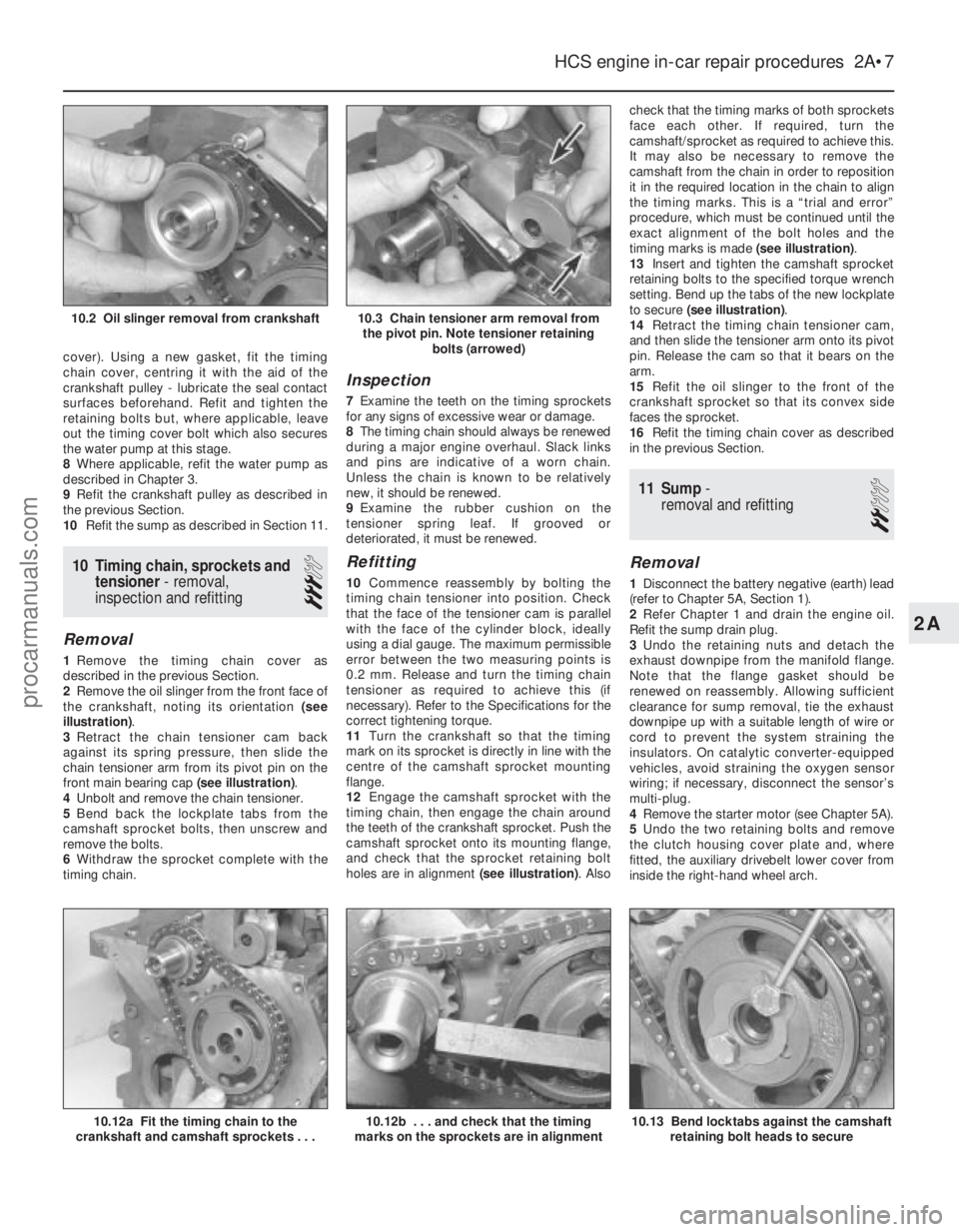
1 Remove the timing chain cover as
described in the previous Section.
2 Remove the oil slinger from the front face of
the crankshaft, noting its orientation (see
illustration) .
3 Retract the chain tensioner cam back
against its spring pressure, then slide the
chain tensioner arm from its pivot pin on the
front main bearing cap (see illustration).
4 Unbolt and remove the chain tensioner.
5 Bend back the lockplate tabs from the
camshaft sprocket bolts, then unscrew and
remove the bolts.
6 Withdraw the sprocket complete with the
timing chain.
Inspection
7 Examine the teeth on the timing sprockets
for any signs of excessive wear or damage.
8 The timing chain should always be renewed
during a major engine overhaul. Slack links
and pins are indicative of a worn chain.
Unless the chain is known to be relatively
new, it should be renewed.
9 Examine the rubber cushion on the
tensioner spring leaf. If grooved or
deteriorated, it must be renewed.
Refitting
10 Commence reassembly by bolting the
timing chain tensioner into position. Check
that the face of the tensioner cam is parallel
with the face of the cylinder block, ideally
using a dial gauge. The maximum permissible
error between the two measuring points is
0.2 mm. Release and turn the timing chain
tensioner as required to achieve this (if
necessary). Refer to the Specifications for the
correct tightening torque.
11 Turn the crankshaft so that the timing
mark on its sprocket is directly in line with the
centre of the camshaft sprocket mounting
flange.
12 Engage the camshaft sprocket with the
timing chain, then engage the chain around
the teeth of the crankshaft sprocket. Push the
camshaft sprocket onto its mounting flange,
and check that the sprocket retaining bolt
holes are in alignment (see illustration). Alsocheck that the timing marks of both sprockets
face each other. If required, turn the
camshaft/sprocket as required to achieve this.
It may also be necessary to remove the
camshaft from the chain in order to reposition
it in the required location in the chain to align
the timing marks. This is a “trial and error”
procedure, which must be continued until the
exact alignment of the bolt holes and the
timing marks is made
(see illustration).
13 Insert and tighten the camshaft sprocket
retaining bolts to the specified torque wrench
setting. Bend up the tabs of the new lockplate
to secure (see illustration) .
14 Retract the timing chain tensioner cam,
and then slide the tensioner arm onto its pivot
pin. Release the cam so that it bears on the
arm.
15 Refit the oil slinger to the front of the
crankshaft sprocket so that its convex side
faces the sprocket.
16 Refit the timing chain cover as described
in the previous Section.
11 Sump -
removal and refitting
2
Removal
1 Disconnect the battery negative (earth) lead
(refer to Chapter 5A, Section 1).
2 Refer Chapter 1 and drain the engine oil.
Refit the sump drain plug.
3 Undo the retaining nuts and detach the
exhaust downpipe from the manifold flange.
Note that the flange gasket should be
renewed on reassembly. Allowing sufficient
clearance for sump removal, tie the exhaust
downpipe up with a suitable length of wire or
cord to prevent the system straining the
insulators. On catalytic converter-equipped
vehicles, avoid straining the oxygen sensor
wiring; if necessary, disconnect the sensor’s
multi-plug.
4 Remove the starter motor (see Chapter 5A).
5 Undo the two retaining bolts and remove
the clutch housing cover plate and, where
fitted, the auxiliary drivebelt lower cover from
inside the right-hand wheel arch.
HCS engine in-car repair procedures 2A•7
10.12a Fit the timing chain to the
crankshaft and camshaft sprockets . . .
10.3 Chain tensioner arm removal from the pivot pin. Note tensioner retaining bolts (arrowed)10.2 Oil slinger removal from crankshaft
10.13 Bend locktabs against the camshaftretaining bolt heads to secure10.12b . . . and check that the timing
marks on the sprockets are in alignment
2A
1595Ford Fiesta Remakeprocarmanuals.com
http://vnx.su
Page 42 of 296
1 General information
How to use this Chapter
This Part of Chapter 2 is devoted to repair
procedures possible while the engine is still
installed in the vehicle, and includes only the
Specifications relevant to those procedures.
Similar information concerning the 1.3 litre
HCS engine, and the 1.6 and 1.8 litre Zetec
engines, will be found in Parts A and C of this
Chapter respectively. Since these procedures
are based on the assumption that the engine
is installed in the vehicle, if the engine has
been removed from the vehicle and mounted
on a stand, some of the preliminary
dismantling steps outlined will not apply.
Information concerning engine/transmission
removal and refitting, and engine overhaul, can
be found in Part D of this Chapter, which also
includes the Specifications relevant to those
procedures.
Engine description
The engine is a four-cylinder, in-line
overhead camshaft type, designated CVH
(Compound Valve angle, Hemispherical
combustion chamber) or PTE (Pent roof, high
Torque, low Emission). The PTE engine was
introduced for 1994 and, apart from
modifications to the cylinder head, camshaft
and intake system, is virtually identical to the
CVH engine it replaces. The engine is
mounted transversely at the front of the
vehicle together with the transmission to form
a combined power unit. The crankshaft is supported in five split-
shell type main bearings within the cast-iron
crankcase. The connecting rod big-end
bearings are split-shell type, and the pistons
are attached by interference-fit gudgeon pins.
Each piston has two compression rings and
one oil control ring.
The cylinder head is of light alloy
construction, and supports the camshaft in five
bearings. Camshaft drive is by a toothed
composite rubber timing belt, which is driven by
a sprocket on the front end of the crankshaft.
The timing belt also drives the water pump,
which is mounted below the cylinder head. Hydraulic cam followers (tappets) operate the
rocker arms and valves. The tappets are
operated by pressurised engine oil. When a
valve closes, the oil passes through a port in the
body of the cam follower, through four grooves
in the plunger and into the cylinder feed
chamber. From the chamber, the oil flows to a
ball-type non-return valve and into the pressure
chamber. The tension of the coil spring causes
the plunger to press against the valve, and so
eliminates any free play. As the cam lifts the
follower, the oil pressure in the pressure
chamber is increased, and the non-return valve
closes off the port feed chamber. This in turn
provides a rigid link between the cam follower,
the cylinder and the plunger. These then rise as a unit to open the valve. The cam follower-to-
cylinder clearance allows the specified quantity
of oil to pass from the pressure chamber, oil only
being allowed past the cylinder bore when the
pressure is high during the moment of the valve
opening. When the valve closes, the escape of
oil will produce a small clearance, and no
pressure will exist in the pressure chamber. The
feed chamber oil then flows through the non-
return valve and into the pressure chamber, so
that the cam follower cylinder can be raised by
the pressure of the coil spring, eliminating free
play until the valve is operated again.
As wear occurs between the rocker arm
and the valve stem, the quantity of oil that
flows into the pressure chamber will be
slightly more than the quantity lost during the
expansion cycle of the cam follower.
Conversely, when the cam follower is
compressed by the expansion of the valve, a
slightly smaller quantity of oil will flow into the
pressure chamber than was lost. A rotor-type oil pump is mounted on the
timing cover end of the engine, and is driven
by a gear on the front end of the crankshaft. A
full-flow type oil filter is fitted, and is mounted
on the side of the crankcase.
Repair operations possible with
the engine in the car
The following work can be carried out with
the engine in the car:
a) Compression pressure - testing.
b) Rocker cover - removal and refitting.
c) Timing belt - removal, refitting and
adjustment.
d) Camshaft oil seal - renewal.
e) Camshaft - removal and refitting.
f) Cylinder head - removal and refitting.
g) Cylinder head and pistons - decarbonising.
h) Crankshaft pulley - removal and refitting.
i) Crankshaft oil seals - renewal.
j) Oil filter renewal.
k) Sump - removal and refitting.
l) Flywheel - removal, inspection and refitting.
m) Mountings - removal and refitting.
Note: It is possible to remove the pistons and
connecting rods (after removing the cylinder
head and sump) without removing the engine.
However, this is not recommended. Work of
this nature is more easily and thoroughly
completed with the engine on the bench, as
described in Chapter 2D.
2 Compression test -
description and interpretation
2
Refer to Section 2 in Part A of this Chap-
ter.
3 Top Dead Centre (TDC) for
No 1 piston - locating
2
1Top dead centre (TDC) is the highest point
of the cylinder that each piston reaches as the
crankshaft turns. Each piston reaches its TDC
position at the end of its compression stroke,
and then again at the end of its exhaust
stroke. For the purpose of engine timing, TDC
on the compression stroke for No 1 piston is
used. No 1 cylinder is at the timing belt end of
the engine. Proceed as follows.
2 Remove the upper timing belt cover as
described in Section 7.
3 Chock the rear wheels then jack up the
front of the car and support it on axle stands
(see “Jacking and Vehicle Support” ).
4 Undo the retaining bolts, and remove the
cover from the underside of the crankshaft
pulley.
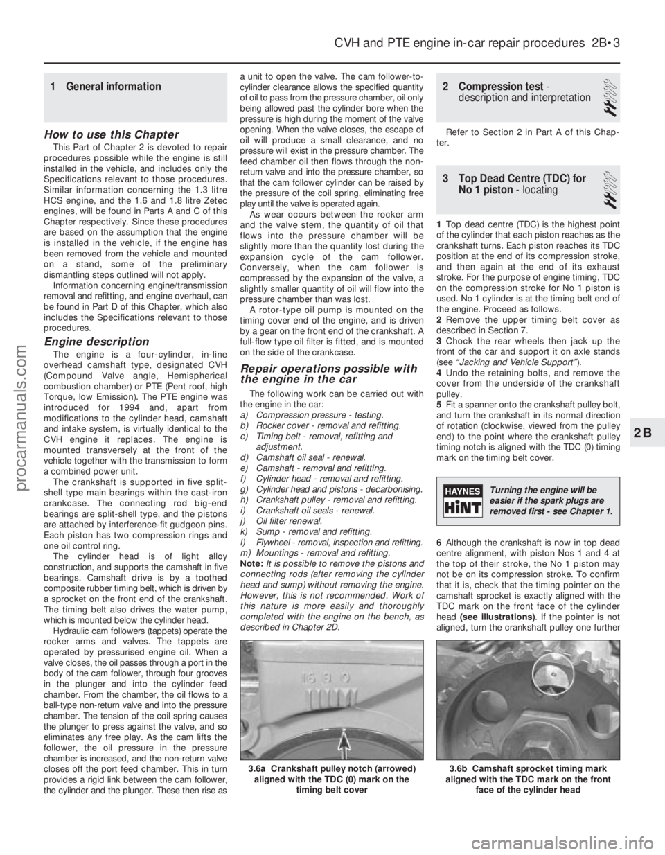
5 Fit a spanner onto the crankshaft pulley bolt,
and turn the crankshaft in its normal direction
of rotation (clockwise, viewed from the pulley
end) to the point where the crankshaft pulley
timing notch is aligned with the TDC (0) timing
mark on the timing belt cover.
6 Although the crankshaft is now in top dead
centre alignment, with piston Nos 1 and 4 at
the top of their stroke, the No 1 piston may
not be on its compression stroke. To confirm
that it is, check that the timing pointer on the
camshaft sprocket is exactly aligned with the
TDC mark on the front face of the cylinder
head (see illustrations) . If the pointer is not
aligned, turn the crankshaft pulley one further
CVH and PTE engine in-car repair procedures 2B•3
3.6b Camshaft sprocket timing mark
aligned with the TDC mark on the front
face of the cylinder head3.6a Crankshaft pulley notch (arrowed)aligned with the TDC (0) mark on the
timing belt cover
2B
1595Ford Fiesta Remake
Turning the engine will be
easier if the spark plugs are
removed first - see Chapter 1.
procarmanuals.com
http://vnx.su
Page 44 of 296
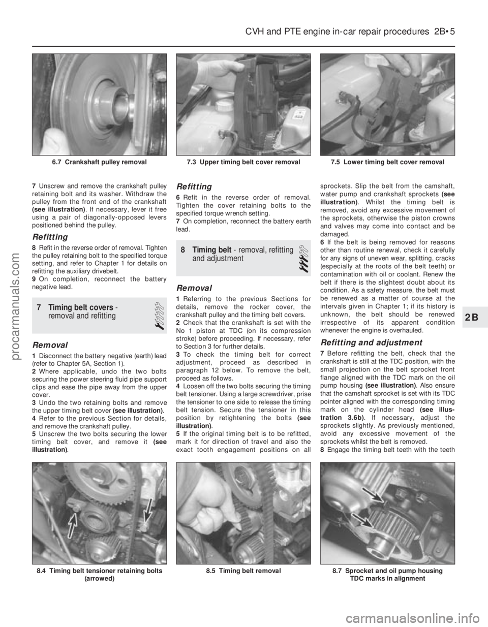
7Unscrew and remove the crankshaft pulley
retaining bolt and its washer. Withdraw the
pulley from the front end of the crankshaft
(see illustration) . If necessary, lever it free
using a pair of diagonally-opposed levers
positioned behind the pulley.
Refitting
8 Refit in the reverse order of removal. Tighten
the pulley retaining bolt to the specified torque
setting, and refer to Chapter 1 for details on
refitting the auxiliary drivebelt.
9 On completion, reconnect the battery
negative lead.
7 Timing belt covers -
removal and refitting
1
Removal
1 Disconnect the battery negative (earth) lead
(refer to Chapter 5A, Section 1).
2 Where applicable, undo the two bolts
securing the power steering fluid pipe support
clips and ease the pipe away from the upper
cover.
3 Undo the two retaining bolts and remove
the upper timing belt cover (see illustration).
4 Refer to the previous Section for details,
and remove the crankshaft pulley.
5 Unscrew the two bolts securing the lower
timing belt cover, and remove it (see
illustration) .
Refitting
6Refit in the reverse order of removal.
Tighten the cover retaining bolts to the
specified torque wrench setting.
7 On completion, reconnect the battery earth
lead.
8 Timing belt - removal, refitting
and adjustment
3
Removal
1 Referring to the previous Sections for
details, remove the rocker cover, the
crankshaft pulley and the timing belt covers.
2 Check that the crankshaft is set with the
No 1 piston at TDC (on its compression
stroke) before proceeding. If necessary, refer
to Section 3 for further details.
3 To check the timing belt for correct
adjustment, proceed as described in
paragraph 12 below. To remove the belt,
proceed as follows.
4 Loosen off the two bolts securing the timing
belt tensioner. Using a large screwdriver, prise
the tensioner to one side to release the timing
belt tension. Secure the tensioner in this
position by retightening the bolts (see
illustration) .
5 If the original timing belt is to be refitted,
mark it for direction of travel and also the
exact tooth engagement positions on all sprockets. Slip the belt from the camshaft,
water pump and crankshaft sprockets
(see
illustration) . Whilst the timing belt is
removed, avoid any excessive movement of
the sprockets, otherwise the piston crowns
and valves may come into contact and be
damaged.
6 If the belt is being removed for reasons
other than routine renewal, check it carefully
for any signs of uneven wear, splitting, cracks
(especially at the roots of the belt teeth) or
contamination with oil or coolant. Renew the
belt if there is the slightest doubt about its
condition. As a safety measure, the belt must
be renewed as a matter of course at the
intervals given in Chapter 1; if its history is
unknown, the belt should be renewed
irrespective of its apparent condition
whenever the engine is overhauled.
Refitting and adjustment
7 Before refitting the belt, check that the
crankshaft is still at the TDC position, with the
small projection on the belt sprocket front
flange aligned with the TDC mark on the oil
pump housing (see illustration) . Also ensure
that the camshaft sprocket is set with its TDC
pointer aligned with the corresponding timing
mark on the cylinder head (see illus-
tration 3.6b) . If necessary, adjust the
sprockets slightly. As previously mentioned,
avoid any excessive movement of the
sprockets whilst the belt is removed.
8 Engage the timing belt teeth with the teeth
CVH and PTE engine in-car repair procedures 2B•5
7.5 Lower timing belt cover removal7.3 Upper timing belt cover removal6.7 Crankshaft pulley removal
8.7 Sprocket and oil pump housing
TDC marks in alignment8.5 Timing belt removal8.4 Timing belt tensioner retaining bolts (arrowed)
2B
1595Ford Fiesta Remakeprocarmanuals.com
http://vnx.su