1989 FORD FIESTA tow bar
[x] Cancel search: tow barPage 9 of 296
1•8Maintenance – component location
1595Ford Fiesta Remake
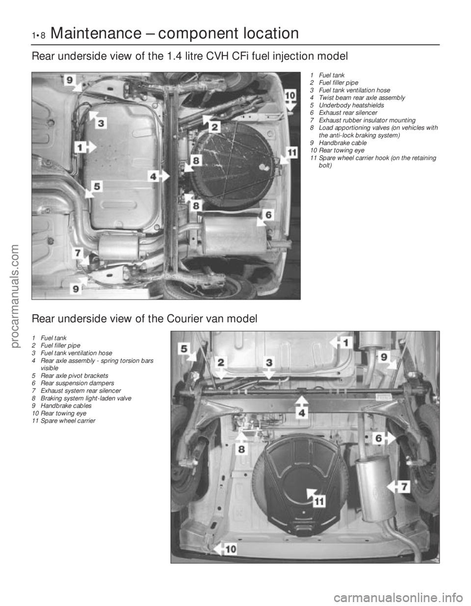
Rear underside view of the 1.4 litre CVH CFi fuel injection model
1 Fuel tank
2 Fuel filler pipe
3 Fuel tank ventilation hose
4 Twist beam rear axle assembly
5 Underbody heatshields
6 Exhaust rear silencer
7 Exhaust rubber insulator mounting
8 Load apportioning valves (on vehicles withthe anti-lock braking system)
9 Handbrake cable
10 Rear towing eye
11 Spare wheel carrier hook (on the retaining
bolt)
Rear underside view of the Courier van model
1 Fuel tank
2 Fuel filler pipe
3 Fuel tank ventilation hose
4 Rear axle assembly - spring torsion bars
visible
5 Rear axle pivot brackets
6 Rear suspension dampers
7 Exhaust system rear silencer
8 Braking system light-laden valve
9 Handbrake cables
10 Rear towing eye
11 Spare wheel carrier
procarmanuals.com
http://vnx.su
Page 45 of 296
of the crankshaft sprocket, and then pull the
belt vertically upright on its right-hand run.
Keep it taut, and engage it with the teeth of
the camshaft sprocket. If the original belt is
being refitted, check that the belt’s direction
of travel is correct, and realign the belt-to-
sprocket marks made during removal, to
ensure that the exact original engagement
positions are retained. When the belt is fully
fitted on the sprockets, check that the
sprocket positions have not altered.
9Carefully manoeuvre the belt around the
tensioner, and engage its teeth with the water
pump sprocket, again ensuring that the TDC
positions of the crankshaft and camshaft
are not disturbed as the belt is finally
located.
10 Refit the lower timing belt cover, and
tighten its retaining bolts to the specified
torque setting. Refit the crankshaft pulley, and
tighten its retaining bolt to the specified
torque setting.
11 To take up belt slack, loosen off the
tensioner and move it towards the front of the
car to apply an initial tension to the belt.
Secure the tensioner in this position, then
remove the flywheel ring gear locking device.
12 Rotate the crankshaft through two full
revolutions in (the normal direction of travel),
returning to the TDC position (camshaft
sprocket-to-cylinder head). Check that the
crankshaft pulley notch is aligned with the
TDC (0) mark on the lower half of the timing
belt cover.
13 Grasp the belt between the thumb and
forefinger, at the midway point between the
crankshaft and camshaft sprockets on the
right-hand side. If the belt tension is correct, it
should just be possible to twist the belt
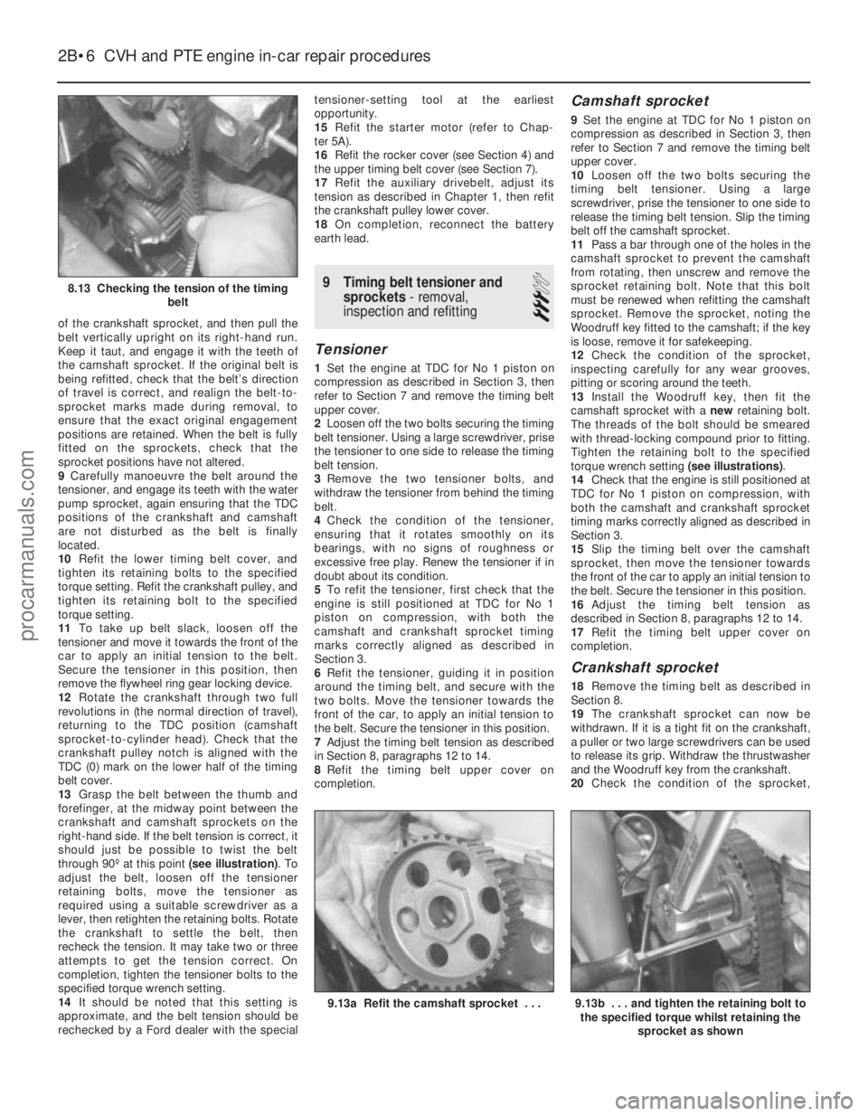
through 90º at this point (see illustration). To
adjust the belt, loosen off the tensioner
retaining bolts, move the tensioner as
required using a suitable screwdriver as a
lever, then retighten the retaining bolts. Rotate
the crankshaft to settle the belt, then
recheck the tension. It may take two or three
attempts to get the tension correct. On
completion, tighten the tensioner bolts to the
specified torque wrench setting.
14 It should be noted that this setting is
approximate, and the belt tension should be
rechecked by a Ford dealer with the special tensioner-setting tool at the earliest
opportunity.
15
Refit the starter motor (refer to Chap-
ter 5A).
16 Refit the rocker cover (see Section 4) and
the upper timing belt cover (see Section 7).
17 Refit the auxiliary drivebelt, adjust its
tension as described in Chapter 1, then refit
the crankshaft pulley lower cover.
18 On completion, reconnect the battery
earth lead.
9 Timing belt tensioner and sprockets - removal,
inspection and refitting
3
Tensioner
1 Set the engine at TDC for No 1 piston on
compression as described in Section 3, then
refer to Section 7 and remove the timing belt
upper cover.
2 Loosen off the two bolts securing the timing
belt tensioner. Using a large screwdriver, prise
the tensioner to one side to release the timing
belt tension.
3 Remove the two tensioner bolts, and
withdraw the tensioner from behind the timing
belt.
4 Check the condition of the tensioner,
ensuring that it rotates smoothly on its
bearings, with no signs of roughness or
excessive free play. Renew the tensioner if in
doubt about its condition.
5 To refit the tensioner, first check that the
engine is still positioned at TDC for No 1
piston on compression, with both the
camshaft and crankshaft sprocket timing
marks correctly aligned as described in
Section 3.
6 Refit the tensioner, guiding it in position
around the timing belt, and secure with the
two bolts. Move the tensioner towards the
front of the car, to apply an initial tension to
the belt. Secure the tensioner in this position.
7 Adjust the timing belt tension as described
in Section 8, paragraphs 12 to 14.
8 Refit the timing belt upper cover on
completion.
Camshaft sprocket
9 Set the engine at TDC for No 1 piston on
compression as described in Section 3, then
refer to Section 7 and remove the timing belt
upper cover.
10 Loosen off the two bolts securing the
timing belt tensioner. Using a large
screwdriver, prise the tensioner to one side to
release the timing belt tension. Slip the timing
belt off the camshaft sprocket.
11 Pass a bar through one of the holes in the
camshaft sprocket to prevent the camshaft
from rotating, then unscrew and remove the
sprocket retaining bolt. Note that this bolt
must be renewed when refitting the camshaft
sprocket. Remove the sprocket, noting the
Woodruff key fitted to the camshaft; if the key
is loose, remove it for safekeeping.
12 Check the condition of the sprocket,
inspecting carefully for any wear grooves,
pitting or scoring around the teeth.
13 Install the Woodruff key, then fit the
camshaft sprocket with a newretaining bolt.
The threads of the bolt should be smeared
with thread-locking compound prior to fitting.
Tighten the retaining bolt to the specified
torque wrench setting (see illustrations).
14 Check that the engine is still positioned at
TDC for No 1 piston on compression, with
both the camshaft and crankshaft sprocket
timing marks correctly aligned as described in
Section 3.
15 Slip the timing belt over the camshaft
sprocket, then move the tensioner towards
the front of the car to apply an initial tension to
the belt. Secure the tensioner in this position.
16 Adjust the timing belt tension as
described in Section 8, paragraphs 12 to 14.
17 Refit the timing belt upper cover on
completion.
Crankshaft sprocket
18 Remove the timing belt as described in
Section 8.
19 The crankshaft sprocket can now be
withdrawn. If it is a tight fit on the crankshaft,
a puller or two large screwdrivers can be used
to release its grip. Withdraw the thrustwasher
and the Woodruff key from the crankshaft.
20 Check the condition of the sprocket,
2B•6 CVH and PTE engine in-car repair procedures
9.13b . . . and tighten the retaining bolt to
the specified torque whilst retaining the
sprocket as shown9.13a Refit the camshaft sprocket . . .
8.13 Checking the tension of the timing belt
1595Ford Fiesta Remakeprocarmanuals.com
http://vnx.su
Page 183 of 296
7Using a suitable socket, firmly press the
primary piston into the master cylinder until
the secondary piston retaining pin becomes
visible through the secondary piston reservoir
opening. Remove the retaining pin using
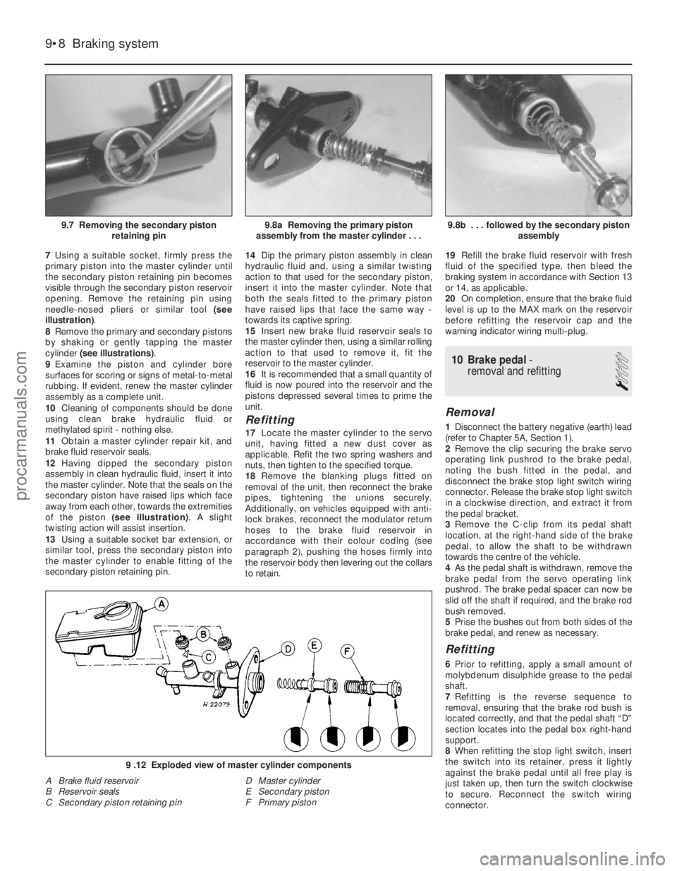
needle-nosed pliers or similar tool (see
illustration) .
8 Remove the primary and secondary pistons
by shaking or gently tapping the master
cylinder (see illustrations) .
9 Examine the piston and cylinder bore
surfaces for scoring or signs of metal-to-metal
rubbing. If evident, renew the master cylinder
assembly as a complete unit.
10 Cleaning of components should be done
using clean brake hydraulic fluid or
methylated spirit - nothing else.
11 Obtain a master cylinder repair kit, and
brake fluid reservoir seals.
12 Having dipped the secondary piston
assembly in clean hydraulic fluid, insert it into
the master cylinder. Note that the seals on the
secondary piston have raised lips which face
away from each other, towards the extremities
of the piston (see illustration) . A slight
twisting action will assist insertion.
13 Using a suitable socket bar extension, or
similar tool, press the secondary piston into
the master cylinder to enable fitting of the
secondary piston retaining pin. 14
Dip the primary piston assembly in clean
hydraulic fluid and, using a similar twisting
action to that used for the secondary piston,
insert it into the master cylinder. Note that
both the seals fitted to the primary piston
have raised lips that face the same way -
towards its captive spring.
15 Insert new brake fluid reservoir seals to
the master cylinder then, using a similar rolling
action to that used to remove it, fit the
reservoir to the master cylinder.
16 It is recommended that a small quantity of
fluid is now poured into the reservoir and the
pistons depressed several times to prime the
unit.
Refitting
17 Locate the master cylinder to the servo
unit, having fitted a new dust cover as
applicable. Refit the two spring washers and
nuts, then tighten to the specified torque.
18 Remove the blanking plugs fitted on
removal of the unit, then reconnect the brake
pipes, tightening the unions securely.
Additionally, on vehicles equipped with anti-
lock brakes, reconnect the modulator return
hoses to the brake fluid reservoir in
accordance with their colour coding (see
paragraph 2), pushing the hoses firmly into
the reservoir body then levering out the collars
to retain. 19
Refill the brake fluid reservoir with fresh
fluid of the specified type, then bleed the
braking system in accordance with Section 13
or 14, as applicable.
20 On completion, ensure that the brake fluid
level is up to the MAX mark on the reservoir
before refitting the reservoir cap and the
warning indicator wiring multi-plug.
10 Brake pedal -
removal and refitting
1
Removal
1 Disconnect the battery negative (earth) lead
(refer to Chapter 5A, Section 1).
2 Remove the clip securing the brake servo
operating link pushrod to the brake pedal,
noting the bush fitted in the pedal, and
disconnect the brake stop light switch wiring
connector. Release the brake stop light switch
in a clockwise direction, and extract it from
the pedal bracket.
3 Remove the C-clip from its pedal shaft
location, at the right-hand side of the brake
pedal, to allow the shaft to be withdrawn
towards the centre of the vehicle.
4 As the pedal shaft is withdrawn, remove the
brake pedal from the servo operating link
pushrod. The brake pedal spacer can now be
slid off the shaft if required, and the brake rod
bush removed.
5 Prise the bushes out from both sides of the
brake pedal, and renew as necessary.
Refitting
6 Prior to refitting, apply a small amount of
molybdenum disulphide grease to the pedal
shaft.
7 Refitting is the reverse sequence to
removal, ensuring that the brake rod bush is
located correctly, and that the pedal shaft “D”
section locates into the pedal box right-hand
support.
8 When refitting the stop light switch, insert
the switch into its retainer, press it lightly
against the brake pedal until all free play is
just taken up, then turn the switch clockwise
to secure. Reconnect the switch wiring
connector.
9•8 Braking system
9 .12 Exploded view of master cylinder components
A Brake fluid reservoir
B Reservoir seals
C Secondary piston retaining pin D Master cylinder
E Secondary piston
F Primary piston
9.8b . . . followed by the secondary piston
assembly9.8a Removing the primary piston
assembly from the master cylinder . . .9.7 Removing the secondary piston retaining pin
1595Ford Fiesta Remakeprocarmanuals.com
http://vnx.su
Page 191 of 296
39With the drivebelt tensioned correctly,
tighten the pivot and adjuster bolts to the
specified torque. Re-check the tension of the
drivebelt after tightening the bolts.
40 Reconnect the rigid brake pipes to the
modulator, tightening the unions to seal the
system.
41 Refit the modulator drivebelt cover and
secure with its two retaining bolts. Take care
not to damage the driveshaft CV joint gaiter as
the cover is eased into position.
42 Refit the belt-break switch to the
modulator drivebelt cover, taking care not to
damage the belt contact arm as it passes
through the cover.
43 Reconnect the modulator return hose by
pushing the hose firmly into its brake fluid
reservoir location, then lever out the collar to
retain it.
44 Refit the front suspension crossmember
and the one-piece undertray, as applicable.
45 Refit the roadwheels, then remove the
axle stands and lower the vehicle to the
ground. Tighten the wheel nuts to the
specified torque.
46 Top-up the brake fluid reservoir using
fresh fluid of the specified type (see “ Weekly
checks ”), then bleed the brake hydraulic
system in accordance with Section 14. Refit
the reservoir filler cap and the warning
indicator wiring multi-plug on completion.
47 Reconnect the battery negative lead.
Modulator drivebelt
48Disconnect the battery negative (earth)
lead (refer to Chapter 5A, Section 1).
49 Chock the rear wheels then jack up the
front of the car and support it on axle stands
(see “Jacking and Vehicle Support” ). Remove
the relevant front roadwheel.
50 Remove the one-piece undertray where
fitted, by turning its bayonet-type fasteners,
and on XR2i models, remove the front
suspension crossmember (see Chapter 10).
51 Remove the belt-break switch from the
relevant drivebelt cover, then remove the
drivebelt cover, as described in the previous
sub-Section.
52 Slacken the modulator pivot and adjuster
bolts to release drivebelt tension, then slip the
drivebelt from the modulator.
53 Remove the track rod end balljoint from
the steering arm on the spindle carrier (see
Chapter 10).
54 Disconnect the anti-roll bar connecting
link (where applicable) and release the brake
hose from their locations on the suspension
strut.
55 Remove the pinch bolt and nut securing
the lower suspension arm balljoint to the
spindle carrier, and separate the balljoint from
the spindle carrier assembly.
56 To release the driveshaft inner CV joint
from the differential, have an assistant pull the
spindle carrier away from the centre of the
vehicle whilst you insert a lever between the
inner CV joint and the transmission casing,
then firmly strike the lever with the flat of the hand, but be careful not to damage adjacent
components. Make provision for escaping
transmission oil, if possible plugging the
opening to prevent excessive loss. Do not
allow the CV joints to bend more than 20°
from the horizontal or internal damage may
occur. If both driveshafts are to be removed,
immobilise the differential by inserting an old
joint or suitable shaft, before the other
driveshaft is removed.
57
Slide the drivebelt off the driveshaft.
58 Remove the snap-ring from the groove in
the splines of the inner CV joint. This snap-
ring must be renewed every time the
driveshaft is withdrawn from the differential.
59 With the drivebelt removed, closely
examine the condition of the belt over its
entire length. Renew the belt if any cracks are
noticed in the fabric at the roots of the teeth, if
there is any abrasion of the fabric facing
material, or if there are any tears starting from
the edge of the belt.
60 If, since the drivebelts were last renewed,
a vehicle has covered more than 30 000 miles
(48 000 km) or a period of more than two
years has elapsed, the drivebelts should be
renewed as a matter of course.
61 Prior to refitting the drivebelt, thoroughly
clean its CV joint pulley location.
62 Fit the drivebelt over the driveshaft then,
with a new snap-ring fitted to the inner CV
joint splines, lubricate the splines with
transmission oil. Remove the temporary plug
and insert the inner CV joint to its
transmission casing location. Press against
the spindle carrier so that the snap-ring
engages fully to hold the CV joint splines in
the differential.
63 Refitting is now a reversal of the removal
procedure, tensioning the drivebelt as
described in the previous sub-Section. Ensure
that the pinch-bolt securing the lower
suspension arm balljoint to the spindle carrier
locates in the annular groove on the balljoint
spindle. Secure the track rod and balljoint,
using a new split pin. Tighten the suspension
components to their specified torque (see
Chapter 10).
64 Check the level of the transmission oil,
and top-up as required (see Chapter 1).
Modulator belt-break switch
65 Modulator belt-break switches are fitted
to each of the two drivebelt covers, and clip
into position. To remove, gently squeeze the
protruding lever on the switch towards the
main switch body and lift out, ensuring that
the belt contact arm does not catch on the
drivebelt cover.
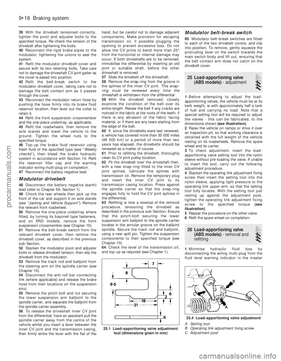
25 Load-apportioning valve (ABS models) - adjustment
3
1Before attempting to adjust the load-
apportioning valves, the vehicle must be at its
kerb weight, ie with approximately half a tank
of fuel and carrying no load. Note that a
special setting tool will be required to adjust
the valves - this can be fabricated, to the
dimensions shown (see illustration).
2 Raise the vehicle on ramps or drive it over
an inspection pit, so that working clearance is
obtained with the full weight of the vehicle
resting on its roadwheels. Remove the spare
wheel and its carrier.
3 To check adjustment, insert the load-
apportioning valve setting tool into the nylon
sleeve without pre-loading the valve. If unable
to insert the tool, carry out the following
adjustment procedure.
4 Slacken the operating link adjustment fixing
screw then insert the setting tool into the
nylon sleeve, applying light pressure to the
operating link upper arm, so that the setting
tool fully locates. With the setting tool just
resting up against the adjustment post,
tighten the operating link adjustment fixing
screw to the specified torque (see
illustration) .
5 Repeat the procedure on the other valve.
6 Refit the spare wheel on completion.
26 Load-apportioning valve
(ABS models) - removal and
refitting
3
1 Minimise hydraulic fluid loss by
disconnecting the wiring multi-plug from the
fluid level warning indicator in the master
9•16 Braking system
25.4 Load-apportioning valve adjustment
A Setting tool
B Operating link adjustment fixing screw
C Adjustment post
25.1 Load-apportioning valve adjustment tool (dimensions given in mm)
1595Ford Fiesta Remakeprocarmanuals.com
http://vnx.su
Page 222 of 296
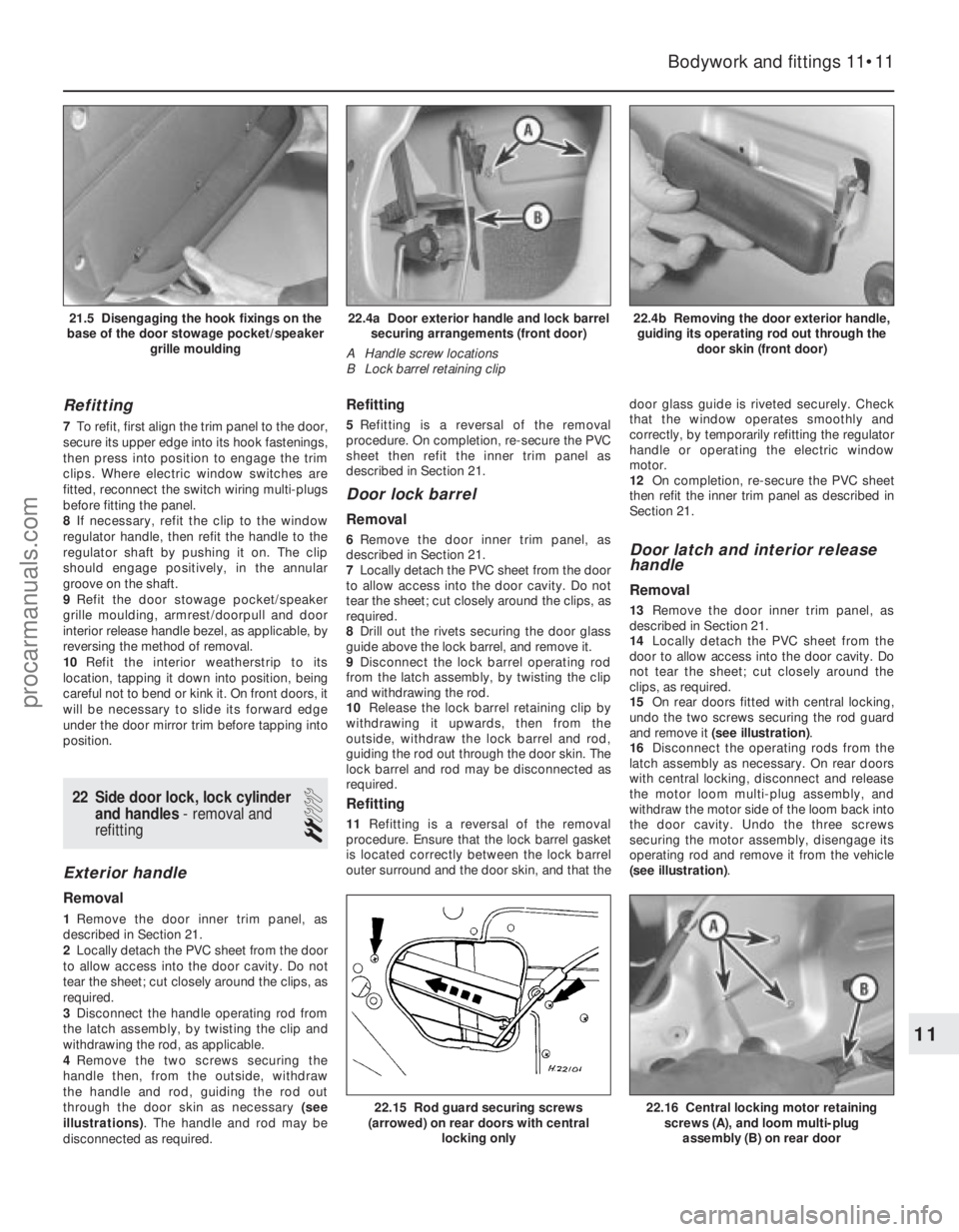
Refitting
7To refit, first align the trim panel to the door,
secure its upper edge into its hook fastenings,
then press into position to engage the trim
clips. Where electric window switches are
fitted, reconnect the switch wiring multi-plugs
before fitting the panel.
8 If necessary, refit the clip to the window
regulator handle, then refit the handle to the
regulator shaft by pushing it on. The clip
should engage positively, in the annular
groove on the shaft.
9 Refit the door stowage pocket/speaker
grille moulding, armrest/doorpull and door
interior release handle bezel, as applicable, by
reversing the method of removal.
10 Refit the interior weatherstrip to its
location, tapping it down into position, being
careful not to bend or kink it. On front doors, it
will be necessary to slide its forward edge
under the door mirror trim before tapping into
position.
22 Side door lock, lock cylinder
and handles - removal and
refitting
2
Exterior handle
Removal
1 Remove the door inner trim panel, as
described in Section 21.
2 Locally detach the PVC sheet from the door
to allow access into the door cavity. Do not
tear the sheet; cut closely around the clips, as
required.
3 Disconnect the handle operating rod from
the latch assembly, by twisting the clip and
withdrawing the rod, as applicable.
4 Remove the two screws securing the
handle then, from the outside, withdraw
the handle and rod, guiding the rod out
through the door skin as necessary (see
illustrations) . The handle and rod may be
disconnected as required.
Refitting
5 Refitting is a reversal of the removal
procedure. On completion, re-secure the PVC
sheet then refit the inner trim panel as
described in Section 21.
Door lock barrel
Removal
6 Remove the door inner trim panel, as
described in Section 21.
7 Locally detach the PVC sheet from the door
to allow access into the door cavity. Do not
tear the sheet; cut closely around the clips, as
required.
8 Drill out the rivets securing the door glass
guide above the lock barrel, and remove it.
9 Disconnect the lock barrel operating rod
from the latch assembly, by twisting the clip
and withdrawing the rod.
10 Release the lock barrel retaining clip by
withdrawing it upwards, then from the
outside, withdraw the lock barrel and rod,
guiding the rod out through the door skin. The
lock barrel and rod may be disconnected as
required.
Refitting
11 Refitting is a reversal of the removal
procedure. Ensure that the lock barrel gasket
is located correctly between the lock barrel
outer surround and the door skin, and that the door glass guide is riveted securely. Check
that the window operates smoothly and
correctly, by temporarily refitting the regulator
handle or operating the electric window
motor.
12
On completion, re-secure the PVC sheet
then refit the inner trim panel as described in
Section 21.
Door latch and interior release
handle
Removal
13 Remove the door inner trim panel, as
described in Section 21.
14 Locally detach the PVC sheet from the
door to allow access into the door cavity. Do
not tear the sheet; cut closely around the
clips, as required.
15 On rear doors fitted with central locking,
undo the two screws securing the rod guard
and remove it (see illustration) .
16 Disconnect the operating rods from the
latch assembly as necessary. On rear doors
with central locking, disconnect and release
the motor loom multi-plug assembly, and
withdraw the motor side of the loom back into
the door cavity. Undo the three screws
securing the motor assembly, disengage its
operating rod and remove it from the vehicle
(see illustration) .
Bodywork and fittings 11•11
22.4b Removing the door exterior handle,
guiding its operating rod out through the door skin (front door)22.4a Door exterior handle and lock barrelsecuring arrangements (front door)
A Handle screw locations
B Lock barrel retaining clip21.5 Disengaging the hook fixings on the
base of the door stowage pocket/speaker grille moulding
22.16 Central locking motor retainingscrews (A), and loom multi-plug
assembly (B) on rear door22.15 Rod guard securing screws
(arrowed) on rear doors with central
locking only
11
1595Ford Fiesta Remakeprocarmanuals.com
http://vnx.su