1989 FORD FIESTA seat adjustment
[x] Cancel search: seat adjustmentPage 2 of 296
1
1595Ford Fiesta Remake
Chapter 1
Routine maintenance and servicing
Air cleaner element renewal . . . . . . . . . . . . . . . . . . . . . . . . . . . . . . . 24
Automatic transmission fluid level check . . . . . . . . . . . . . . . . . . . . . 20
Automatic transmission fluid renewal . . . . . . . . . . . . . . . . . . . . . . . . 26
Auxiliary drivebelt check and renewal . . . . . . . . . . . . . . . . . . . . . . . . 4
Bodywork, paint and exterior trim check . . . . . . . . . . . . . . . . . . . . . 18
Brake check . . . . . . . . . . . . . . . . . . . . . . . . . . . . . . . . . . . .\
. . . . . . . 14
Brake fluid renewal . . . . . . . . . . . . . . . . . . . . . . . . . . . . . . . . . . . .\
. . 31
Coolant renewal . . . . . . . . . . . . . . . . . . . . . . . . . . . . . . . . . . . .\
. . . . 23
Door, tailgate and bonnet check and lubrication . . . . . . . . . . . . . . . 16
Driveshaft rubber gaiter and CV joint check . . . . . . . . . . . . . . . . . . . 11
Emission control system check . . . . . . . . . . . . . . . . . . . . . . . . . . . . . 25
Engine compartment wiring check . . . . . . . . . . . . . . . . . . . . . . . . . . 6
Engine oil and filter renewal . . . . . . . . . . . . . . . . . . . . . . . . . . . . . . . 3
Exhaust system check . . . . . . . . . . . . . . . . . . . . . . . . . . . . . . . . . . . 12
Front wheel alignment check . . . . . . . . . . . . . . . . . . . . . . . . . . . . . . 28
Fuel filter renewal . . . . . . . . . . . . . . . . . . . . . . . . . . . . . . . . . . . .\
. . . 30Handbrake adjustment . . . . . . . . . . . . . . . . . . . . . . . . . . . . . . . . . . . 27
Idle speed and mixture check and adjustment . . . . . . . . . . . . . . . . 9
Idle speed control valve cleaning and maintenance . . . . . . . . . . . . . 22
Intensive maintenance . . . . . . . . . . . . . . . . . . . . . . . . . . . . . . . . . . . 2
Introduction . . . . . . . . . . . . . . . . . . . . . . . . . . . . . . . . . . . .\
. . . . . . . . 1
Manual transmission oil level check . . . . . . . . . . . . . . . . . . . . . . . . . 8
Road test . . . . . . . . . . . . . . . . . . . . . . . . . . . . . . . . . . . .\
. . . . . . . . . . 19
Roadwheel nut tightness check . . . . . . . . . . . . . . . . . . . . . . . . . . . . 15
Seat belt check . . . . . . . . . . . . . . . . . . . . . . . . . . . . . . . . . . . .\
. . . . . 17
Spark plug renewal and HT component check . . . . . . . . . . . . . . . . . 21
Steering, suspension and roadwheel check . . . . . . . . . . . . . . . . . . . 10
Timing belt renewal . . . . . . . . . . . . . . . . . . . . . . . . . . . . . . . . . . . .\
. . 29
Underbody and fuel/brake line check . . . . . . . . . . . . . . . . . . . . . . . . 13
Underbonnet check for fluid leaks and hose condition . . . . . . . . . . 5
Valve clearance adjustment . . . . . . . . . . . . . . . . . . . . . . . . . . . . . . . 7
1•1
Contents
Easy,
suitable for
novice with little
experience Fairly easy,
suitable
for beginner with
some experience Fairly difficult,
suitable for competent
DIY mechanic
Difficult,
suitable for
experienced DIY
mechanic Very difficult,
suitable for expert DIY
or professional
Degrees of difficulty
54321
procarmanuals.com
http://vnx.su
Page 5 of 296
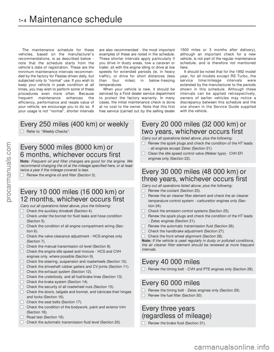
The maintenance schedule for these
vehicles, based on the manufacturer’s
recommendations, is as described below -
note that the schedule starts from the
vehicle’s date of registration. These are the
minimum maintenance intervals recommen-
ded by the factory for Fiestas driven daily, but
subjected only to “normal” use. If you wish to
keep your vehicle in peak condition at all
times, you may wish to perform some of these
procedures even more often. Because
frequent maintenance enhances the
efficiency, performance and resale value of
your vehicle, we encourage you to do so. If
your usage is not “normal”, shorter intervals are also recommended - the most important
examples of these are noted in the schedule.
These shorter intervals apply particularly if
you drive in dusty areas, tow a caravan or
trailer, sit with the engine idling or drive at low
speeds for extended periods (ie, in heavy
traffic), or drive for short distances (less
than four miles) in below-freezing
temperatures.
When your vehicle is new, it should be
serviced by a Ford dealer service department
to protect the factory warranty. In many
cases, the initial maintenance check is done
at no cost to the owner. Note that this first
free service (carried out by the selling dealer 1500 miles or 3 months after delivery),
although an important check for a new
vehicle, is not part of the regular maintenance
schedule, and is therefore not mentioned
here.
It should be noted that for the 1992 model
year, for all models except RS Turbo, the
service time/mileage intervals were
extended by the manufacturer to the periods
shown in this schedule. Although these
intervals can be applied retrospectively,
owners of earlier vehicles may notice a
discrepancy between this schedule and the
one shown in the Service Guide supplied
with the vehicle.
1•4Maintenance schedule
1595Ford Fiesta Remake
Every 250 miles (400 km) or weekly
m
m Refer to “Weekly Checks” .
Every 5000 miles (8000 km) or
6 months, whichever occurs first
Note: Frequent oil and filter changes are good for the engine. We
recommend changing the oil at the mileage specified here, or at least
twice a year if the mileage covered is less.
m m Renew the engine oil and filter (Section 3).
Every 10 000 miles (16 000 km) or
12 months, whichever occurs first
Carry out all operations listed above, plus the following:
m mCheck the auxiliary drivebelt (Section 4).
m
m Check under the bonnet for fluid leaks and hose condition
(Section 5).
m
m Check the condition of all engine compartment wiring (Sec-
tion 6).
m
m Check the valve clearance adjustment - HCS engines only
(Section 7).
m
m Check the manual transmission oil level (Section 8).
m
m Check the engine idle speed and mixture - HCS and CVH
engines only, where possible (Section 9).
m
m Check the steering, suspension and roadwheels (Section 10).
m
m Check the driveshaft rubber gaiters and CV joints (Section 11).
m
m Check the exhaust system (Section 12).
m
m Check the underbody, and all fuel/brake lines (Section 13).
m
m Check the brake system (Section 14).
m
m Check the security of all roadwheel nuts (Section 15).
m
m Check the doors, tailgate and bonnet, and lubricate their hinges
and locks (Section 16).
m
m Check the seat belts (Section 17).
m
m Check the condition of the bodywork, paint and exterior trim
(Section 18).
m
m Road test (Section 19).
m
m Check the automatic transmission fluid level (Section 20).
Every 20 000 miles (32 000 km) or
two years, whichever occurs first
Carry out all operations listed above, plus the following:
m mRenew the spark plugs and check the condition of the HT leads
- all engines except Zetec (Section 21).
m
m Clean the idle speed control valve (Weber type) - CVH EFi
engines only (Section 22).
Every 30 000 miles (48 000 km) or
three years, whichever occurs first
Carry out all operations listed above, plus the following:
m m Renew the coolant (Section 23).
m
m Renew the air cleaner filter element and check the air cleaner
temperature control system - carburettor engines only (Sec-
tion 24).
m m Check the emission control systems (Section 25).
m
m Renew the spark plugs and check the condition of the HT leads
- Zetec engines (Section 21).
m
m Renew the automatic transmission fluid (Section 26).
m
m Check the handbrake adjustment (Section 27).
m
m Check the front wheel alignment (Section 28).
Note: If the vehicle is used regularly in dusty or polluted conditions,
the air cleaner filter element should be renewed at more frequent
intervals.
Every 40 000 miles
m
m Renew the timing belt - CVH and PTE engines only (Section 29).
Every 60 000 miles
m
mRenew the timing belt - Zetec engines only (Section 29).
m
m Renew the fuel filter (Section 30).
Every three years
(regardless of mileage)
m m Renew the brake fluid (Section 31).
procarmanuals.com
http://vnx.su
Page 24 of 296
SEFi fuel injection models
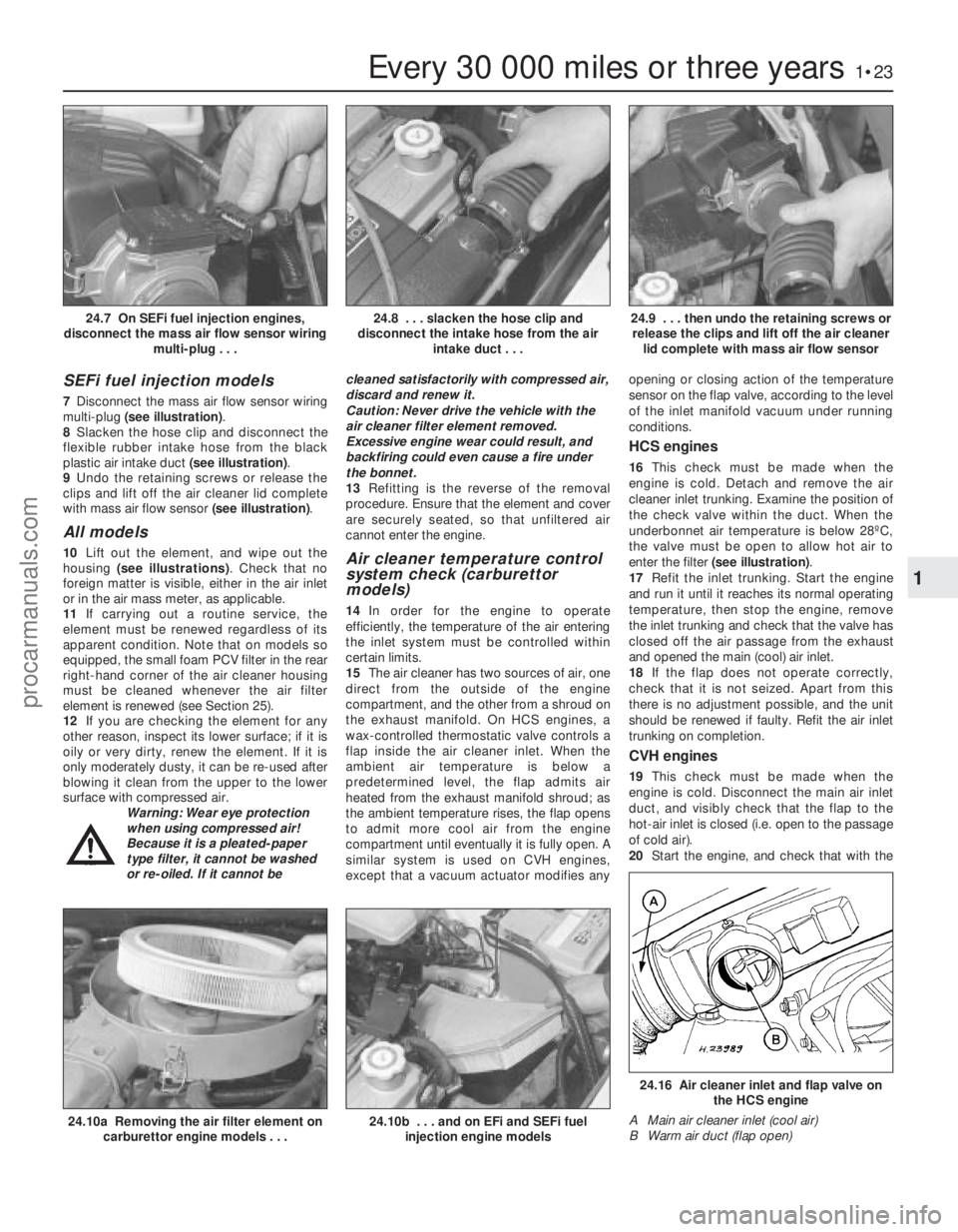
7Disconnect the mass air flow sensor wiring
multi-plug (see illustration) .
8 Slacken the hose clip and disconnect the
flexible rubber intake hose from the black
plastic air intake duct (see illustration).
9 Undo the retaining screws or release the
clips and lift off the air cleaner lid complete
with mass air flow sensor (see illustration).
All models
10Lift out the element, and wipe out the
housing (see illustrations) . Check that no
foreign matter is visible, either in the air inlet
or in the air mass meter, as applicable.
11 If carrying out a routine service, the
element must be renewed regardless of its
apparent condition. Note that on models so
equipped, the small foam PCV filter in the rear
right-hand corner of the air cleaner housing
must be cleaned whenever the air filter
element is renewed (see Section 25).
12 If you are checking the element for any
other reason, inspect its lower surface; if it is
oily or very dirty, renew the element. If it is
only moderately dusty, it can be re-used after
blowing it clean from the upper to the lower
surface with compressed air. Warning: Wear eye protection
when using compressed air!
Because it is a pleated-paper
type filter, it cannot be washed
or re-oiled. If it cannot be cleaned satisfactorily with compressed air,
discard and renew it.
Caution: Never drive the vehicle with the
air cleaner filter element removed.
Excessive engine wear could result, and
backfiring could even cause a fire under
the bonnet.
13
Refitting is the reverse of the removal
procedure. Ensure that the element and cover
are securely seated, so that unfiltered air
cannot enter the engine.Air cleaner temperature control
system check (carburettor
models)
14 In order for the engine to operate
efficiently, the temperature of the air entering
the inlet system must be controlled within
certain limits.
15 The air cleaner has two sources of air, one
direct from the outside of the engine
compartment, and the other from a shroud on
the exhaust manifold. On HCS engines, a
wax-controlled thermostatic valve controls a
flap inside the air cleaner inlet. When the
ambient air temperature is below a
predetermined level, the flap admits air
heated from the exhaust manifold shroud; as
the ambient temperature rises, the flap opens
to admit more cool air from the engine
compartment until eventually it is fully open. A
similar system is used on CVH engines,
except that a vacuum actuator modifies any opening or closing action of the temperature
sensor on the flap valve, according to the level
of the inlet manifold vacuum under running
conditions.
HCS engines
16
This check must be made when the
engine is cold. Detach and remove the air
cleaner inlet trunking. Examine the position of
the check valve within the duct. When the
underbonnet air temperature is below 28ºC,
the valve must be open to allow hot air to
enter the filter (see illustration) .
17 Refit the inlet trunking. Start the engine
and run it until it reaches its normal operating
temperature, then stop the engine, remove
the inlet trunking and check that the valve has
closed off the air passage from the exhaust
and opened the main (cool) air inlet.
18 If the flap does not operate correctly,
check that it is not seized. Apart from this
there is no adjustment possible, and the unit
should be renewed if faulty. Refit the air inlet
trunking on completion.
CVH engines
19 This check must be made when the
engine is cold. Disconnect the main air inlet
duct, and visibly check that the flap to the
hot-air inlet is closed (i.e. open to the passage
of cold air).
20 Start the engine, and check that with the
Every 30 000 miles or three years1•23
24.9 . . . then undo the retaining screws or
release the clips and lift off the air cleaner lid complete with mass air flow sensor24.8 . . . slacken the hose clip and
disconnect the intake hose from the air intake duct . . .24.7 On SEFi fuel injection engines,
disconnect the mass air flow sensor wiring multi-plug . . .
24.16 Air cleaner inlet and flap valve onthe HCS engine
A Main air cleaner inlet (cool air)
B Warm air duct (flap open)
24.10b . . . and on EFi and SEFi fuel injection engine models24.10a Removing the air filter element oncarburettor engine models . . .
1
1595Ford Fiesta Remakeprocarmanuals.com
http://vnx.su
Page 31 of 296
Refitting
5Thoroughly clean the rocker cover, and
scrape away any traces of old gasket
remaining on the cover and cylinder head
mating surfaces.
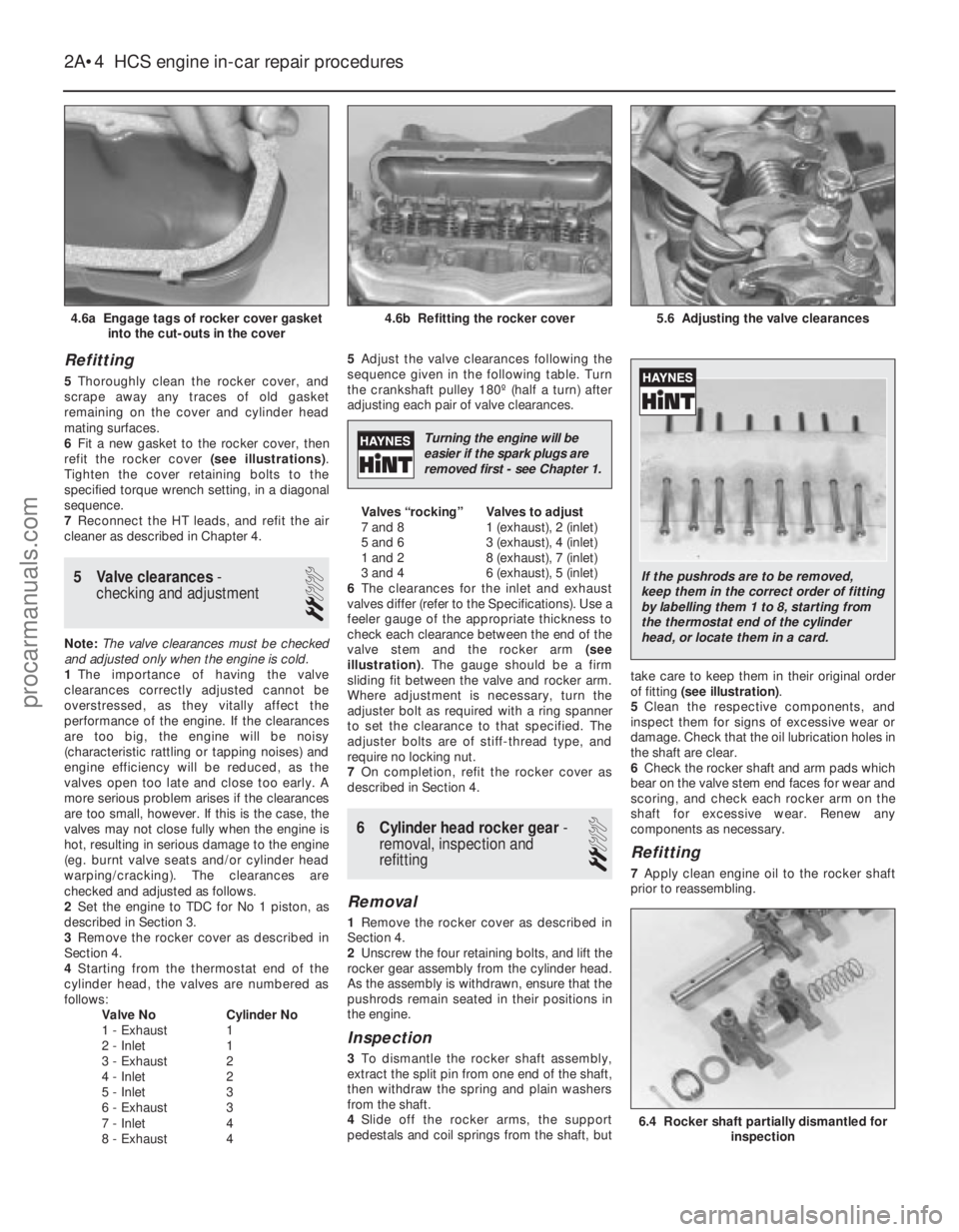
6 Fit a new gasket to the rocker cover, then
refit the rocker cover (see illustrations).
Tighten the cover retaining bolts to the
specified torque wrench setting, in a diagonal
sequence.
7 Reconnect the HT leads, and refit the air
cleaner as described in Chapter 4.
5 Valve clearances -
checking and adjustment
2
Note: The valve clearances must be checked
and adjusted only when the engine is cold.
1 The importance of having the valve
clearances correctly adjusted cannot be
overstressed, as they vitally affect the
performance of the engine. If the clearances
are too big, the engine will be noisy
(characteristic rattling or tapping noises) and
engine efficiency will be reduced, as the
valves open too late and close too early. A
more serious problem arises if the clearances
are too small, however. If this is the case, the
valves may not close fully when the engine is
hot, resulting in serious damage to the engine
(eg. burnt valve seats and/or cylinder head
warping/cracking). The clearances are
checked and adjusted as follows.
2 Set the engine to TDC for No 1 piston, as
described in Section 3.
3 Remove the rocker cover as described in
Section 4.
4 Starting from the thermostat end of the
cylinder head, the valves are numbered as
follows: Valve No Cylinder No
1 - Exhaust 1
2 - Inlet 1
3 - Exhaust 2
4 - Inlet 2
5 - Inlet 3
6 - Exhaust 3
7 - Inlet 4
8 - Exhaust 4 5
Adjust the valve clearances following the
sequence given in the following table. Turn
the crankshaft pulley 180º (half a turn) after
adjusting each pair of valve clearances.
Valves “rocking” Valves to adjust
7 and 8 1 (exhaust), 2 (inlet)
5 and 6 3 (exhaust), 4 (inlet)
1 and 2 8 (exhaust), 7 (inlet)
3 and 4 6 (exhaust), 5 (inlet)
6 The clearances for the inlet and exhaust
valves differ (refer to the Specifications). Use a
feeler gauge of the appropriate thickness to
check each clearance between the end of the
valve stem and the rocker arm (see
illustration) . The gauge should be a firm
sliding fit between the valve and rocker arm.
Where adjustment is necessary, turn the
adjuster bolt as required with a ring spanner
to set the clearance to that specified. The
adjuster bolts are of stiff-thread type, and
require no locking nut.
7 On completion, refit the rocker cover as
described in Section 4.
6 Cylinder head rocker gear -
removal, inspection and
refitting
2
Removal
1 Remove the rocker cover as described in
Section 4.
2 Unscrew the four retaining bolts, and lift the
rocker gear assembly from the cylinder head.
As the assembly is withdrawn, ensure that the
pushrods remain seated in their positions in
the engine.
Inspection
3 To dismantle the rocker shaft assembly,
extract the split pin from one end of the shaft,
then withdraw the spring and plain washers
from the shaft.
4 Slide off the rocker arms, the support
pedestals and coil springs from the shaft, but take care to keep them in their original order
of fitting
(see illustration) .
5 Clean the respective components, and
inspect them for signs of excessive wear or
damage. Check that the oil lubrication holes in
the shaft are clear.
6 Check the rocker shaft and arm pads which
bear on the valve stem end faces for wear and
scoring, and check each rocker arm on the
shaft for excessive wear. Renew any
components as necessary.
Refitting
7 Apply clean engine oil to the rocker shaft
prior to reassembling.
2A•4 HCS engine in-car repair procedures
6.4 Rocker shaft partially dismantled for inspection
5.6 Adjusting the valve clearances4.6b Refitting the rocker cover4.6a Engage tags of rocker cover gasketinto the cut-outs in the cover
1595Ford Fiesta Remake
Turning the engine will be
easier if the spark plugs are
removed first - see Chapter 1.
If the pushrods are to be removed,
keep them in the correct order of fitting
by labelling them 1 to 8, starting from
the thermostat end of the cylinder
head, or locate them in a card.
procarmanuals.com
http://vnx.su
Page 43 of 296
complete turn, and all the markings should
now align.
7With the engine set at No 1 piston on TDC
compression, refit the crankshaft pulley cover,
lower the vehicle and refit the upper timing
belt cover.
4 Cylinder head rocker cover -
removal and refitting
2
Removal
1 Disconnect the battery negative (earth) lead
(refer to Chapter 5A, Section 1).
2 Remove the air cleaner assembly and air
inlet components as necessary for access as
described in the relevant Part of Chapter 4.
Disconnect the crankcase ventilation hose
from the rocker cover.
3 Remove the timing belt upper cover as
described in Section 7.
4 Referring to the relevant Part of Chapter 4
for details, disconnect the accelerator cable
from the throttle linkage and from the adjuster
bracket above the rocker cover. Position the
cable out of the way.
5 Where applicable, disconnect the choke
cable from the carburettor, referring to
Chapter 4A for details.
6 Unscrew and remove the rocker cover
retaining bolts and washers, then lift the cover
from the cylinder head. Note that a new
rocker cover gasket will be needed on
refitting.
Refitting
7 Before refitting the rocker cover, clean the
mating surfaces of both the cylinder head and
the cover.
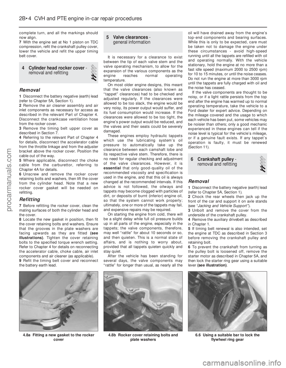
8 Locate the new gasket in position, then fit
the cover retaining bolts and washers. Ensure
that the grooves in the plate washers are
facing upwards as they are fitted (see
illustrations) . Tighten the cover retaining
bolts to the specified torque wrench setting.
Refer to Chapter 4 for details on reconnecting
the accelerator cable, choke cable, air inlet
components and air cleaner (as applicable).
9 Refit the timing belt cover and reconnect
the battery earth lead.
5 Valve clearances -
general information
It is necessary for a clearance to exist
between the tip of each valve stem and the
valve operating mechanism, to allow for the
expansion of the various components as the
engine reaches normal operating
temperature. On most older engine designs, this meant
that the valve clearances (also known as
“tappet” clearances) had to be checked and
adjusted regularly. If the clearances were
allowed to be too slack, the engine would be
very noisy, its power output would suffer, and
its fuel consumption would increase. If the
clearances were allowed to be too tight, the
engine’s power output would be reduced, and
the valves and their seats could be severely
damaged. These engines employ hydraulic tappets
which use the lubricating system’s oil
pressure to automatically take up the
clearance between each camshaft lobe and
its respective valve stem. Therefore, there is
no need for regular checking and adjustment
of the valve clearances. However, it is
essential that only good-quality oil of the
recommended viscosity and specification is
used in the engine, and that this oil is always
changed at the recommended intervals. If this
advice is not followed, the oilways and
tappets may become clogged with particles of
dirt, or deposits of burnt (inferior) engine oil,
so that the system cannot work properly;
ultimately, one or more of the tappets may fail,
and expensive repairs may be required. On starting the engine from cold, there will
be a slight delay while full oil pressure builds
up in all parts of the engine, especially in the
tappets; the valve components, therefore,
may well “rattle” for about 10 seconds or so,
and then quieten. This is a normal state of
affairs, and is nothing to worry about,
provided that all tappets quieten quickly and
stay quiet. After the vehicle has been standing for
several days, the valve components may
“rattle” for longer than usual, as nearly all the oil will have drained away from the engine’s
top-end components and bearing surfaces.
While this is only to be expected, care must
be taken not to damage the engine under
these circumstances - avoid high-speed
running until all the tappets are refilled with oil
and operating normally. With the vehicle
stationary, hold the engine at no more than a
fast idle speed (maximum 2000 to 2500 rpm)
for 10 to 15 minutes, or until the noise ceases.
Do not run the engine at more than 3000 rpm
until the tappets are fully charged with oil and
the noise has ceased.
If the valve components are thought to be
noisy, or if a light rattle persists from the top
end after the engine has warmed up to normal
operating temperature, take the vehicle to a
Ford dealer for expert advice. Depending on
the mileage covered and the usage to which
each vehicle has been put, some vehicles may
be noisier than others; only a good mechanic
experienced in these engines can tell if the
noise level is typical for the vehicle’s mileage,
or if a genuine fault exists. If any tappet’s
operation is faulty, it must be renewed
(Section 11).
6 Crankshaft pulley -
removal and refitting
2
Removal
1 Disconnect the battery negative (earth) lead
(refer to Chapter 5A, Section 1).
2 Chock the rear wheels then jack up the
front of the car and support it on axle stands
(see “Jacking and Vehicle Support” ).
3 Unbolt and remove the cover from the
underside of the crankshaft pulley.
4 Remove the auxiliary drivebelt as described
in Chapter 1.
5 If timing belt renewal is also intended, set
the engine at TDC as described in Section 3
before removing the crankshaft pulley and
retaining bolt.
6 To prevent the crankshaft from turning as
the pulley bolt is loosened off, remove the
starter motor as described in Chapter 5A, and
then lock the starter ring gear using a suitable
lever (see illustration) .
2B•4 CVH and PTE engine in-car repair procedures
6.6 Using a suitable bar to lock the
flywheel ring gear4.8b Rocker cover retaining bolts and plate washers4.8a Fitting a new gasket to the rocker cover
1595Ford Fiesta Remakeprocarmanuals.com
http://vnx.su
Page 56 of 296
fitted with three piston rings: two
compression rings and an oil control ring.
After manufacture, the cylinder bores and
piston skirts are measured and classified into
three grades, which must be carefully
matched together, to ensure the correct
piston/cylinder clearance; no oversizes are
available to permit reboring.The inlet and exhaust valves are each
closed by coil springs; they operate in guides
which are shrink-fitted into the cylinder head,
as are the valve seat inserts. Both camshafts are driven by the same
toothed timing belt, each operating eight
valves via self-adjusting hydraulic tappets,
thus eliminating the need for routine checking
and adjustment of the valve clearances. Each
camshaft rotates in five bearings that are line-
bored directly in the cylinder head and the
(bolted-on) bearing caps; this means that the
bearing caps are not available separately from
the cylinder head, and must not be
interchanged with caps from another engine. The water pump is bolted to the right-hand
end of the cylinder block, inboard of the
timing belt, and is driven with the power
steering pump and alternator by a flat
“polyvee”-type auxiliary drivebelt from the
crankshaft pulley.
When working on this engine, note that
Torx-type (both male and female heads) and
hexagon socket (Allen head) fasteners are
widely used; a good selection of bits, with the
necessary adapters, will be required, so that
these can be unscrewed without damage and,
on reassembly, tightened to the torque
wrench settings specified. Lubrication is by means of an eccentric-
rotor trochoidal pump, which is mounted on
the crankshaft right-hand end, and draws oil
through a strainer located in the sump. The
pump forces oil through an externally-
mounted full-flow cartridge-type filter - on
some versions of the engine, an oil cooler is
fitted to the oil filter mounting, so that clean oil
entering the engine’s galleries is cooled by the
main engine cooling system.
Repair operations possible with
the engine in the car
The following work can be carried out with
the engine in the car:
a) Compression pressure - testing.
b) Cylinder head cover - removal and
refitting.
c) Timing belt covers - removal and refitting.
d) Timing belt - renewal.
e) Timing belt tensioner and sprockets - removal and refitting.
f) Camshaft oil seals - renewal.
g) Camshafts and hydraulic tappets - removal and refitting.
h) Cylinder head - removal and refitting.
i) Cylinder head and pistons - decarbonising.
j) Sump - removal and refitting.
k) Crankshaft oil seals - renewal.
l) Oil pump - removal and refitting. m)
Flywheel/driveplate - removal and
refitting.
n) Engine/transmission mountings - removal and refitting.
Note: It is possible to remove the pistons and
connecting rods (after removing the cylinder
head and sump) without removing the engine.
However, this is not recommended. Work of
this nature is more easily and thoroughly
completed with the engine on the bench, as
described in Chapter 2D.
2 Compression test -
description and interpretation
2
Refer to Section 2 in Part A of this Chapter.
3 Top Dead Centre (TDC) for No 1 piston - locating
2
1Top dead centre (TDC) is the highest point
of the cylinder that each piston reaches as the
crankshaft turns. Each piston reaches its TDC
position at the end of its compression stroke,
and then again at the end of its exhaust
stroke. For the purpose of engine timing, TDC
on the compression stroke for No 1 piston is
used. No 1 cylinder is at the timing belt end of
the engine. Proceed as follows.
2 Disconnect the battery negative (earth) lead
(refer to Chapter 5A, Section 1).
3 Chock the rear wheels then jack up the
front of the car and support it on axle stands
(see “Jacking and Vehicle Support” ). Remove
the right-hand roadwheel.
4 Remove the auxiliary drivebelt cover (see
Chapter 1) to expose the crankshaft pulley
and timing marks.
5 Fit a spanner onto the crankshaft pulley
bolt, and turn the crankshaft in its normal
direction of rotation (clockwise, viewed from
the pulley end). 6
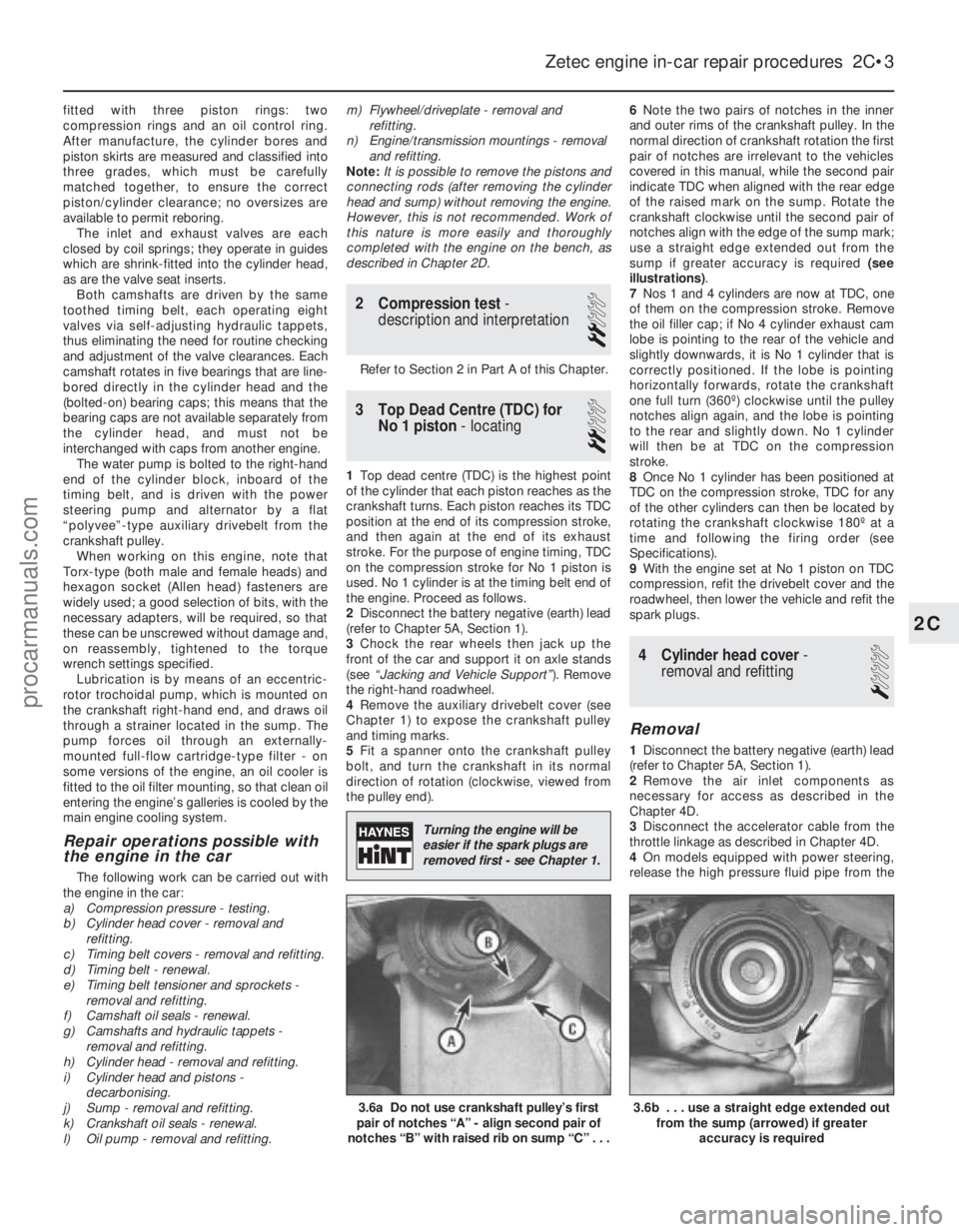
Note the two pairs of notches in the inner
and outer rims of the crankshaft pulley. In the
normal direction of crankshaft rotation the first
pair of notches are irrelevant to the vehicles
covered in this manual, while the second pair
indicate TDC when aligned with the rear edge
of the raised mark on the sump. Rotate the
crankshaft clockwise until the second pair of
notches align with the edge of the sump mark;
use a straight edge extended out from the
sump if greater accuracy is required (see
illustrations) .
7 Nos 1 and 4 cylinders are now at TDC, one
of them on the compression stroke. Remove
the oil filler cap; if No 4 cylinder exhaust cam
lobe is pointing to the rear of the vehicle and
slightly downwards, it is No 1 cylinder that is
correctly positioned. If the lobe is pointing
horizontally forwards, rotate the crankshaft
one full turn (360º) clockwise until the pulley
notches align again, and the lobe is pointing
to the rear and slightly down. No 1 cylinder
will then be at TDC on the compression
stroke.
8 Once No 1 cylinder has been positioned at
TDC on the compression stroke, TDC for any
of the other cylinders can then be located by
rotating the crankshaft clockwise 180º at a
time and following the firing order (see
Specifications).
9 With the engine set at No 1 piston on TDC
compression, refit the drivebelt cover and the
roadwheel, then lower the vehicle and refit the
spark plugs.
4 Cylinder head cover -
removal and refitting
1
Removal
1 Disconnect the battery negative (earth) lead
(refer to Chapter 5A, Section 1).
2 Remove the air inlet components as
necessary for access as described in the
Chapter 4D.
3 Disconnect the accelerator cable from the
throttle linkage as described in Chapter 4D.
4 On models equipped with power steering,
release the high pressure fluid pipe from the
Zetec engine in-car repair procedures 2C•3
3.6b . . . use a straight edge extended out from the sump (arrowed) if greater
accuracy is required3.6a Do not use crankshaft pulley’s first
pair of notches “A” - align second pair of
notches “B” with raised rib on sump “C” . . .
2C
1595Ford Fiesta Remake
Turning the engine will be
easier if the spark plugs are
removed first - see Chapter 1.
procarmanuals.com
http://vnx.su
Page 108 of 296
1 General information andprecautions
General information
The fuel system on all models with
carburettor induction comprises a rear-
mounted fuel tank, a mechanical diaphragm
fuel pump, a carburettor and an air cleaner. The fuel tank is mounted at the rear, under
the floorpan behind the rear seats. The tank
has a “ventilation-to-atmosphere system”
through a combined roll-over/anti-trickle fill
valve assembly, located in the left-hand rear
wheel arch. A filler neck sensing pipe, integral
with the fuel tank filler pipe, will shut off the
petrol pump filler gun when the predetermined
maximum level of fuel is reached in the tank,
so preventing spillage and wastage. A
conventional fuel level sender unit is mounted
in the top face of the fuel tank. One of two fuel pump types will be fitted,
depending on the engine type. On HCS
engines, the fuel pump is operated by a
pivoting rocker arm; one end rests on an
eccentric lobe on the engine camshaft, and
the other end is attached to the fuel pump
diaphragm. The pump fitted to the CVH
engine is operated by a separate pushrod,
one end rests on an eccentric lobe on the
engine camshaft, and the other rests on the
pump actuating rod which operates the
diaphragm. Both types of mechanical pump
incorporate a nylon mesh filter, and are of
sealed type (they cannot be serviced or
overhauled). Four different types of Weber carburettor
are featured in the range, further details being
given in later Sections of this Chapter. The air cleaner incorporates a “waxstat”
controlled air inlet, supplying either hot air
from a shroud mounted around the exhaust
manifold, or cool air from a duct in the front of
the vehicle.
Precautions
Warning: Petrol is extremely
flammable - great care must be
taken when working on any part of the fuel system. Do not smoke or allow
any naked flames or uncovered light bulbs
near the work area. Note that gas powered
domestic appliances with pilot flames,
such as heaters, boilers and tumble
dryers, also present a fire hazard - bear
this in mind if you are working in an area
where such appliances are present.
Always keep a suitable fire extinguisher
close to the work area and familiarise
yourself with its operation before starting
work. Wear eye protection when working
on fuel systems and wash off any fuel spilt
on bare skin immediately with soap and
water. Note that fuel vapour is just as
dangerous as liquid fuel; a vessel that has
just been emptied of liquid fuel will still
contain vapour and can be potentially
explosive. Petrol is a highly dangerous and
volatile liquid, and the precautions
necessary when handling it cannot be
overstressed.
Many of the operations described in this
Chapter involve the disconnection of fuel
lines, which may cause an amount of fuel
spillage. Before commencing work, refer
to the above Warning and the information
in “Safety first” at the beginning of this
manual.
When working with fuel system
components, pay particular attention to
cleanliness - dirt entering the fuel system
may cause blockages which will lead to
poor running.
Certain adjustment points in the fuel system
are protected by tamperproof caps, plugs or
seals. In some territories, it is an offence to
drive a vehicle with broken or missing
tamperproof seals. Before disturbing a
tamperproof seal, first check that no local or
national laws will be broken by doing so, and
fit a new tamperproof seal after adjustment is
complete, where required by law. Do not
break tamperproof seals on any vehicle whilst
it is still under warranty. Carburettors are delicate instruments, and
care must be taken not to disturb any
components unnecessarily. Before attempting
work on a carburettor, ensure that the relevant
spares are available; it should be noted that a complete strip down of a carburettor is
unlikely to cure a fault which is not
immediately obvious, without introducing new
problems. If persistent problems occur, it is
recommended that the services of a Ford
dealer or a carburettor specialist are sought.
Most dealers will be able to provide
carburettor rejetting and servicing facilities.
Where necessary, it may be possible to
purchase a reconditioned carburettor.
2 Air cleaner
-
removal and refitting
1
Note: Air cleaner element renewal and air
cleaner temperature control system checks
are described in Chapter 1.
Removal
1 Disconnect the battery negative (earth) lead
(refer to Chapter 5A, Section 1).
2 On CVH engine models, pull free and
release the accelerator cable from the locating
clip on the side of the air cleaner.
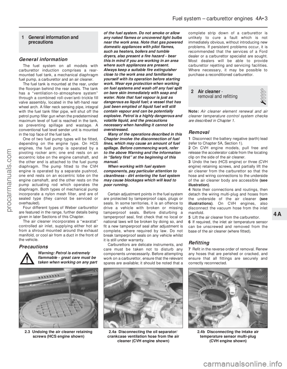
3 Undo the two (HCS engine) or three (CVH
engine) retaining screws, and partially lift the
air cleaner from the carburettor so that the
hose and wiring connections to the underside
of the air cleaner body are accessible (see
illustration) .
4 Note their connections and routings, then
detach the wiring multi-plug and hoses from
the underside of the air cleaner (see
illustrations) . On CVH engines, also
disconnect the vacuum hose from the inlet
manifold.
5 Lift the air cleaner from the carburettor.
6 If required, the inlet air temperature sensor
can be unscrewed and removed from the
base of the air cleaner (where fitted).
Refitting
7 Refit in the reverse order of removal. Renew
any hoses that are perished or cracked, and
ensure that all fittings are securely and
correctly reconnected.
Fuel system – carburettor engines 4A•3
2.4b Disconnecting the intake air temperature sensor multi-plug
(CVH engine shown)2.4a Disconnecting the oil separator/
crankcase ventilation hose from the air
cleaner (CVH engine shown)2.3 Undoing the air cleaner retainingscrews (HCS engine shown)
4A
1595Ford Fiesta Remakeprocarmanuals.com
http://vnx.su
Page 118 of 296
14Prise free and remove the tamperproof
seal, then unscrew and remove the idle
mixture adjustment screw.
15 Undo the retaining screws, and remove
the throttle housing from the carburettor main
body.
Cleaning and inspection
16 Wash the carburettor components,
drillings and passages with clean petrol, then
blow them dry using a low-pressure air line. A
high-pressure air line must not be applied to
the accelerator pump discharge assembly or
the pump supply valve, as they each contain a
rubber Vernay valve, and these can easily be
damaged under high pressure. Never use a
piece of wire for cleaning purposes.
17 Examine all of the carburettor
components for signs of damage or wear,
paying particular attention to the diaphragms,
throttle spindle and plates, needle valve and
mixture screw; the power valve jet is adjacent
to the primary main jet. Renew all
diaphragms, sealing washers and gaskets as
a matter of course.
Reassembly
18 Refit the throttle housing to the
carburettor main body (fitting a new gasket),
and secure with its retaining screws.
19 Refit the idle mixture adjustment screw.
Make an initial adjustment by screwing it fully
in (but do not overtighten or screw it onto its
seat), then unscrew it two full turns.
20 Where fitted, reassemble the throttle
kicker, ensuring that its diaphragm lies flat,
and that the relative position of the operating
link to the kicker cover is correct.
21 Fit the power valve, ensuring that its
diaphragm lies flat and the vacuum
gallery aligns with the diaphragm and
housing.
22 Refit the accelerator pump. Take care not
damage the valve as it is inserted, and check
that the O-ring seal is correctly located on the
end of the valve. Check that the valve is not
trapped by the spring.
23 Refit the accelerator pump discharge jet.
Take care not to damage the valve and/or the
O-ring seal, and ensure that they are correctly
located.
24 Commence reassembly of the upper body
by inserting the emulsion tubes and the air
correction jets into their respective ports (as
noted during removal).
25 Screw the anti-dieseling solenoid into
position. Ensure that the aluminium washer is
fitted, and take care not to overtighten the
valve.
26 Refit the needle valve and the float, and
adjust the float setting as described in Sec-
tion 20.
27 Refit the choke control mechanism, and
secure with its three retaining screws.
28 Locate a new gasket onto the mating
face, then refit the carburettor upper body to
the main body. As they are reassembled, take
care not to snag the float on the carburettor main body. Fit and tighten the retaining
screws to secure.
29
On completion, refit the carburettor as
described in Section 23. Where applicable,
check and adjust the throttle kicker setting
(Section 21) after adjusting the idle speed and
mixture settings.
25 Carburettor (Weber DFTM) -
description
The carburettor operates in essentially the
same manner as TLDM instrument described
in Section 18, but the following features
should be noted. A throttle kicker is fitted to both manual
transmission, and CTX automatic trans-
mission models, the operation of the unit is
described in Section 18. The secondary venturi (barrel) is vacuum-
operated on manual transmission models. On
CTX automatic transmission equipped models
it is operated sequentially. A bleed back solenoid (if fitted) is used to
control the amount of fuel being delivered to
the venturi by the action of the accelerator
pump. Idle speed and mixture adjustment
procedures are described in Chapter 1, but it
is important to note that accurate adjustments
can only be made using the necessary
equipment.
26 Carburettor (Weber DFTM) -
fast-idle speed adjustment
4
Refer to the procedure contained in Sec-
tion 19, but note the following points:
a) When removing the air cleaner, do not disconnect the vacuum supply or
crankcase ventilation hoses; the air
cleaner should be positioned clear of the
carburettor assembly.
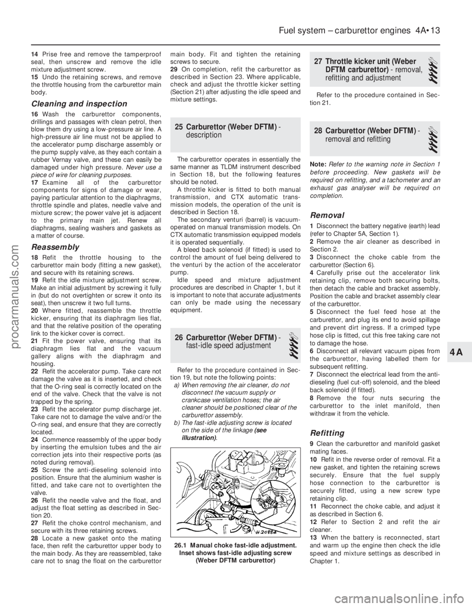
b) The fast-idle adjusting screw is located
on the side of the linkage (see
illustration) .
27 Throttle kicker unit (Weber
DFTM carburettor) - removal,
refitting and adjustment
4
Refer to the procedure contained in Sec-
tion 21.
28 Carburettor (Weber DFTM) -
removal and refitting
4
Note: Refer to the warning note in Section 1
before proceeding. New gaskets will be
required on refitting, and a tachometer and an
exhaust gas analyser will be required on
completion.
Removal
1 Disconnect the battery negative (earth) lead
(refer to Chapter 5A, Section 1).
2 Remove the air cleaner as described in
Section 2.
3 Disconnect the choke cable from the
carburettor (Section 6).
4 Carefully prise out the accelerator link
retaining clip, remove both securing bolts,
then detach the cable and bracket assembly.
Position the cable and bracket assembly clear
of the carburettor.
5 Disconnect the fuel feed hose at the
carburettor, and plug its end to avoid spillage
and prevent dirt ingress. If a crimped type
hose clip is fitted, cut this free taking care not
to damage the hose.
6 Disconnect all relevant vacuum pipes from
the carburettor, having labelled them for
subsequent refitting.
7 Disconnect the electrical lead from the anti-
dieseling (fuel cut-off) solenoid, and the bleed
back solenoid (if fitted).
8 Remove the four nuts securing the
carburettor to the inlet manifold, then
withdraw it from the vehicle.
Refitting
9 Clean the carburettor and manifold gasket
mating faces.
10 Refit in the reverse order of removal. Fit a
new gasket, and tighten the retaining screws
securely. Ensure that the fuel supply
hose connection to the carburettor is
securely fitted, using a new screw type
retaining clip.
11 Reconnect the choke cable, and adjust it
as described in Section 6.
12 Refer to Section 2 and refit the air
cleaner.
13 When the battery is reconnected, start
and warm up the engine then check the idle
speed and mixture settings as described in
Chapter 1.
Fuel system – carburettor engines 4A•13
26.1 Manual choke fast-idle adjustment. Inset shows fast-idle adjusting screw (Weber DFTM carburettor)
4A
1595Ford Fiesta Remakeprocarmanuals.com
http://vnx.su