1989 FORD FIESTA mileage
[x] Cancel search: mileagePage 5 of 296
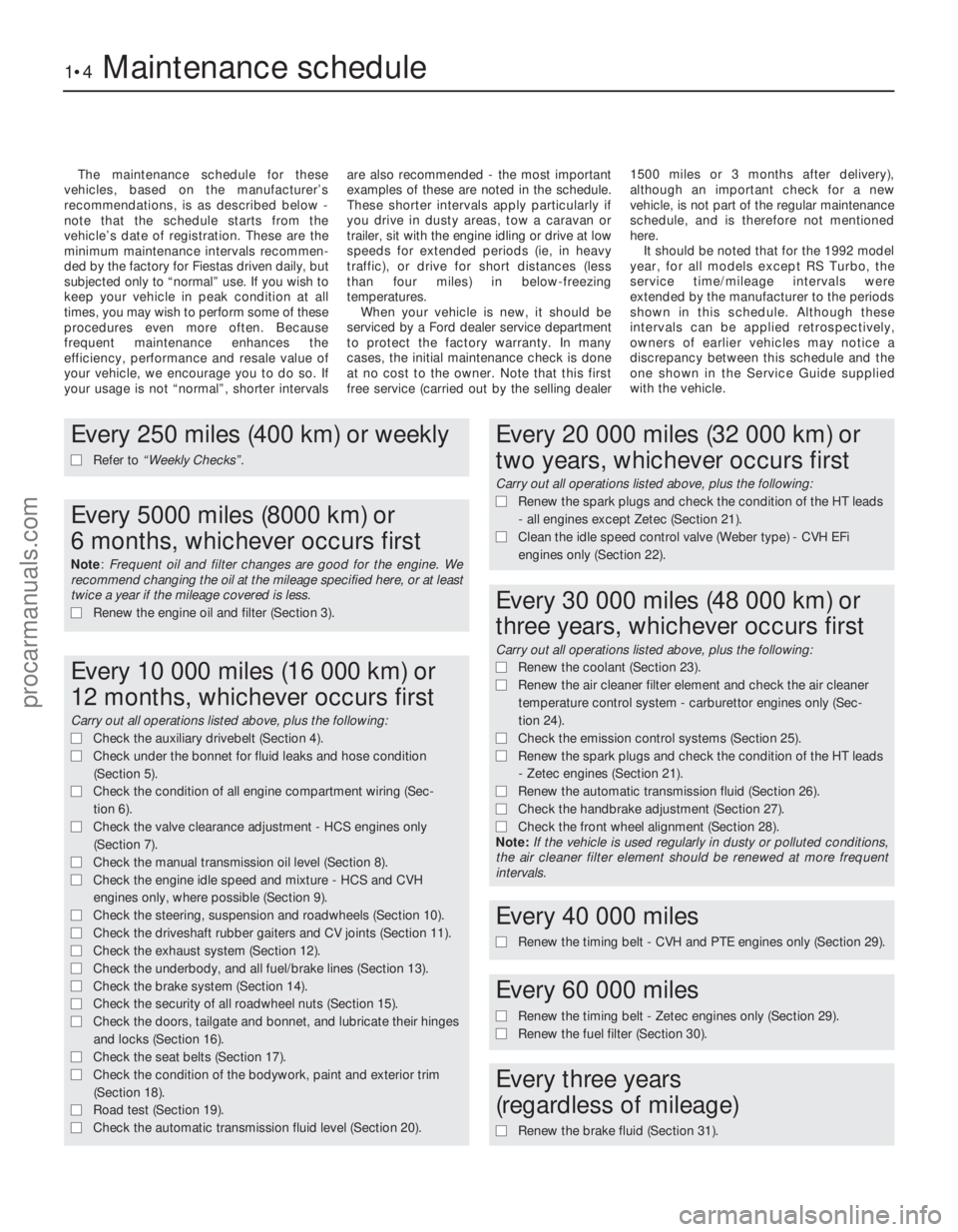
The maintenance schedule for these
vehicles, based on the manufacturer’s
recommendations, is as described below -
note that the schedule starts from the
vehicle’s date of registration. These are the
minimum maintenance intervals recommen-
ded by the factory for Fiestas driven daily, but
subjected only to “normal” use. If you wish to
keep your vehicle in peak condition at all
times, you may wish to perform some of these
procedures even more often. Because
frequent maintenance enhances the
efficiency, performance and resale value of
your vehicle, we encourage you to do so. If
your usage is not “normal”, shorter intervals are also recommended - the most important
examples of these are noted in the schedule.
These shorter intervals apply particularly if
you drive in dusty areas, tow a caravan or
trailer, sit with the engine idling or drive at low
speeds for extended periods (ie, in heavy
traffic), or drive for short distances (less
than four miles) in below-freezing
temperatures.
When your vehicle is new, it should be
serviced by a Ford dealer service department
to protect the factory warranty. In many
cases, the initial maintenance check is done
at no cost to the owner. Note that this first
free service (carried out by the selling dealer 1500 miles or 3 months after delivery),
although an important check for a new
vehicle, is not part of the regular maintenance
schedule, and is therefore not mentioned
here.
It should be noted that for the 1992 model
year, for all models except RS Turbo, the
service time/mileage intervals were
extended by the manufacturer to the periods
shown in this schedule. Although these
intervals can be applied retrospectively,
owners of earlier vehicles may notice a
discrepancy between this schedule and the
one shown in the Service Guide supplied
with the vehicle.
1•4Maintenance schedule
1595Ford Fiesta Remake
Every 250 miles (400 km) or weekly
m
m Refer to “Weekly Checks” .
Every 5000 miles (8000 km) or
6 months, whichever occurs first
Note: Frequent oil and filter changes are good for the engine. We
recommend changing the oil at the mileage specified here, or at least
twice a year if the mileage covered is less.
m m Renew the engine oil and filter (Section 3).
Every 10 000 miles (16 000 km) or
12 months, whichever occurs first
Carry out all operations listed above, plus the following:
m mCheck the auxiliary drivebelt (Section 4).
m
m Check under the bonnet for fluid leaks and hose condition
(Section 5).
m
m Check the condition of all engine compartment wiring (Sec-
tion 6).
m
m Check the valve clearance adjustment - HCS engines only
(Section 7).
m
m Check the manual transmission oil level (Section 8).
m
m Check the engine idle speed and mixture - HCS and CVH
engines only, where possible (Section 9).
m
m Check the steering, suspension and roadwheels (Section 10).
m
m Check the driveshaft rubber gaiters and CV joints (Section 11).
m
m Check the exhaust system (Section 12).
m
m Check the underbody, and all fuel/brake lines (Section 13).
m
m Check the brake system (Section 14).
m
m Check the security of all roadwheel nuts (Section 15).
m
m Check the doors, tailgate and bonnet, and lubricate their hinges
and locks (Section 16).
m
m Check the seat belts (Section 17).
m
m Check the condition of the bodywork, paint and exterior trim
(Section 18).
m
m Road test (Section 19).
m
m Check the automatic transmission fluid level (Section 20).
Every 20 000 miles (32 000 km) or
two years, whichever occurs first
Carry out all operations listed above, plus the following:
m mRenew the spark plugs and check the condition of the HT leads
- all engines except Zetec (Section 21).
m
m Clean the idle speed control valve (Weber type) - CVH EFi
engines only (Section 22).
Every 30 000 miles (48 000 km) or
three years, whichever occurs first
Carry out all operations listed above, plus the following:
m m Renew the coolant (Section 23).
m
m Renew the air cleaner filter element and check the air cleaner
temperature control system - carburettor engines only (Sec-
tion 24).
m m Check the emission control systems (Section 25).
m
m Renew the spark plugs and check the condition of the HT leads
- Zetec engines (Section 21).
m
m Renew the automatic transmission fluid (Section 26).
m
m Check the handbrake adjustment (Section 27).
m
m Check the front wheel alignment (Section 28).
Note: If the vehicle is used regularly in dusty or polluted conditions,
the air cleaner filter element should be renewed at more frequent
intervals.
Every 40 000 miles
m
m Renew the timing belt - CVH and PTE engines only (Section 29).
Every 60 000 miles
m
mRenew the timing belt - Zetec engines only (Section 29).
m
m Renew the fuel filter (Section 30).
Every three years
(regardless of mileage)
m m Renew the brake fluid (Section 31).
procarmanuals.com
http://vnx.su
Page 10 of 296
3 Engine oil and filter renewal
1
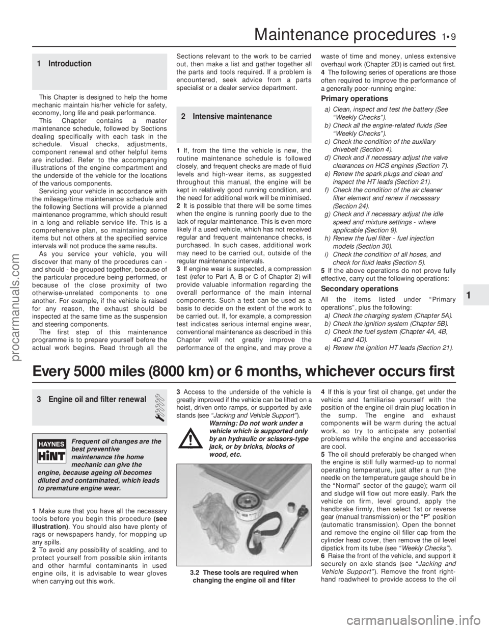
1Make sure that you have all the necessary
tools before you begin this procedure (see
illustration) . You should also have plenty of
rags or newspapers handy, for mopping up
any spills.
2 To avoid any possibility of scalding, and to
protect yourself from possible skin irritants
and other harmful contaminants in used
engine oils, it is advisable to wear gloves
when carrying out this work. 3
Access to the underside of the vehicle is
greatly improved if the vehicle can be lifted on a
hoist, driven onto ramps, or supported by axle
stands (see “Jacking and Vehicle Support” ).
Warning: Do not work under a
vehicle which is supported only
by an hydraulic or scissors-type
jack, or by bricks, blocks of
wood, etc. 4
If this is your first oil change, get under the
vehicle and familiarise yourself with the
position of the engine oil drain plug location in
the sump. The engine and exhaust
components will be warm during the actual
work, so try to anticipate any potential
problems while the engine and accessories
are cool.
5 The oil should preferably be changed when
the engine is still fully warmed-up to normal
operating temperature, just after a run (the
needle on the temperature gauge should be in
the “Normal” sector of the gauge); warm oil
and sludge will flow out more easily. Park the
vehicle on firm, level ground, apply the
handbrake firmly, then select 1st or reverse
gear (manual transmission) or the “P” position
(automatic transmission). Open the bonnet
and remove the engine oil filler cap from the
cylinder head cover, then remove the oil level
dipstick from its tube (see “Weekly Checks”).
6 Raise the front of the vehicle, and support it
securely on axle stands (see “Jacking and
Vehicle Support” ). Remove the front right-
hand roadwheel to provide access to the oil
1 Introduction
This Chapter is designed to help the home
mechanic maintain his/her vehicle for safety,
economy, long life and peak performance.
This Chapter contains a master
maintenance schedule, followed by Sections
dealing specifically with each task in the
schedule. Visual checks, adjustments,
component renewal and other helpful items
are included. Refer to the accompanying
illustrations of the engine compartment and
the underside of the vehicle for the locations
of the various components.
Servicing your vehicle in accordance with
the mileage/time maintenance schedule and
the following Sections will provide a planned
maintenance programme, which should result
in a long and reliable service life. This is a
comprehensive plan, so maintaining some
items but not others at the specified service
intervals will not produce the same results. As you service your vehicle, you will
discover that many of the procedures can -
and should - be grouped together, because of
the particular procedure being performed, or
because of the close proximity of two
otherwise-unrelated components to one
another. For example, if the vehicle is raised
for any reason, the exhaust should be
inspected at the same time as the suspension
and steering components.
The first step of this maintenance
programme is to prepare yourself before the
actual work begins. Read through all the Sections relevant to the work to be carried
out, then make a list and gather together all
the parts and tools required. If a problem is
encountered, seek advice from a parts
specialist or a dealer service department.
2 Intensive maintenance
1
If, from the time the vehicle is new, the
routine maintenance schedule is followed
closely, and frequent checks are made of fluid
levels and high-wear items, as suggested
throughout this manual, the engine will be
kept in relatively good running condition, and
the need for additional work will be minimised.
2 It is possible that there will be some times
when the engine is running poorly due to the
lack of regular maintenance. This is even more
likely if a used vehicle, which has not received
regular and frequent maintenance checks, is
purchased. In such cases, additional work
may need to be carried out, outside of the
regular maintenance intervals.
3 If engine wear is suspected, a compression
test (refer to Part A, B or C of Chapter 2) will
provide valuable information regarding the
overall performance of the main internal
components. Such a test can be used as a
basis to decide on the extent of the work to
be carried out. If, for example, a compression
test indicates serious internal engine wear,
conventional maintenance as described in this
Chapter will not greatly improve the
performance of the engine, and may prove a waste of time and money, unless extensive
overhaul work (Chapter 2D) is carried out first.
4
The following series of operations are those
often required to improve the performance of
a generally poor-running engine:
Primary operations
a) Clean, inspect and test the battery (See
“Weekly Checks”).
b) Check all the engine-related fluids (See
“Weekly Checks”).
c) Check the condition of the auxiliary drivebelt (Section 4).
d) Check and if necessary adjust the valve
clearances on HCS engines (Section 7).
e) Renew the spark plugs and clean and inspect the HT leads (Section 21).
f) Check the condition of the air cleaner filter element and renew if necessary
(Section 24).
g) Check and if necessary adjust the idle speed and mixture settings - where
applicable (Section 9).
h) Renew the fuel filter - fuel injection models (Section 30).
i) Check the condition of all hoses, and check for fluid leaks (Section 5).
5 If the above operations do not prove fully
effective, carry out the following operations:
Secondary operations
All the items listed under “Primary
operations”, plus the following: a) Check the charging system (Chapter 5A).
b) Check the ignition system (Chapter 5B).
c) Check the fuel system (Chapter 4A, 4B,
4C and 4D).
e) Renew the ignition HT leads (Section 21).
Maintenance procedures1•9
3.2 These tools are required when changing the engine oil and filter
1
1595Ford Fiesta Remake
Every 5000 miles (8000 km) or 6 months, whichever occurs first
Frequent oil changes are the
best preventive
maintenance the home
mechanic can give the
engine, because ageing oil becomes
diluted and contaminated, which leads
to premature engine wear.
procarmanuals.com
http://vnx.su
Page 43 of 296
complete turn, and all the markings should
now align.
7With the engine set at No 1 piston on TDC
compression, refit the crankshaft pulley cover,
lower the vehicle and refit the upper timing
belt cover.
4 Cylinder head rocker cover -
removal and refitting
2
Removal
1 Disconnect the battery negative (earth) lead
(refer to Chapter 5A, Section 1).
2 Remove the air cleaner assembly and air
inlet components as necessary for access as
described in the relevant Part of Chapter 4.
Disconnect the crankcase ventilation hose
from the rocker cover.
3 Remove the timing belt upper cover as
described in Section 7.
4 Referring to the relevant Part of Chapter 4
for details, disconnect the accelerator cable
from the throttle linkage and from the adjuster
bracket above the rocker cover. Position the
cable out of the way.
5 Where applicable, disconnect the choke
cable from the carburettor, referring to
Chapter 4A for details.
6 Unscrew and remove the rocker cover
retaining bolts and washers, then lift the cover
from the cylinder head. Note that a new
rocker cover gasket will be needed on
refitting.
Refitting
7 Before refitting the rocker cover, clean the
mating surfaces of both the cylinder head and
the cover.
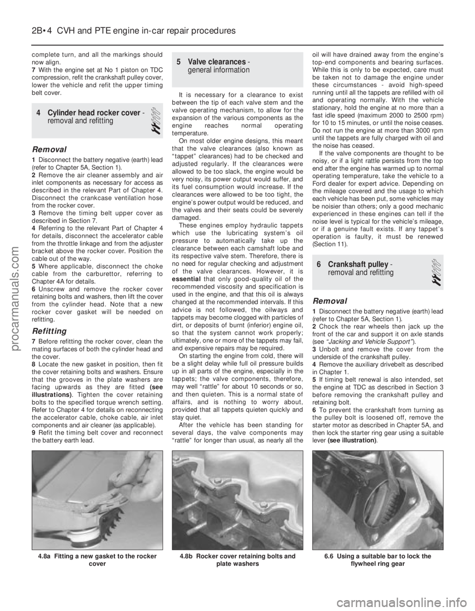
8 Locate the new gasket in position, then fit
the cover retaining bolts and washers. Ensure
that the grooves in the plate washers are
facing upwards as they are fitted (see
illustrations) . Tighten the cover retaining
bolts to the specified torque wrench setting.
Refer to Chapter 4 for details on reconnecting
the accelerator cable, choke cable, air inlet
components and air cleaner (as applicable).
9 Refit the timing belt cover and reconnect
the battery earth lead.
5 Valve clearances -
general information
It is necessary for a clearance to exist
between the tip of each valve stem and the
valve operating mechanism, to allow for the
expansion of the various components as the
engine reaches normal operating
temperature. On most older engine designs, this meant
that the valve clearances (also known as
“tappet” clearances) had to be checked and
adjusted regularly. If the clearances were
allowed to be too slack, the engine would be
very noisy, its power output would suffer, and
its fuel consumption would increase. If the
clearances were allowed to be too tight, the
engine’s power output would be reduced, and
the valves and their seats could be severely
damaged. These engines employ hydraulic tappets
which use the lubricating system’s oil
pressure to automatically take up the
clearance between each camshaft lobe and
its respective valve stem. Therefore, there is
no need for regular checking and adjustment
of the valve clearances. However, it is
essential that only good-quality oil of the
recommended viscosity and specification is
used in the engine, and that this oil is always
changed at the recommended intervals. If this
advice is not followed, the oilways and
tappets may become clogged with particles of
dirt, or deposits of burnt (inferior) engine oil,
so that the system cannot work properly;
ultimately, one or more of the tappets may fail,
and expensive repairs may be required. On starting the engine from cold, there will
be a slight delay while full oil pressure builds
up in all parts of the engine, especially in the
tappets; the valve components, therefore,
may well “rattle” for about 10 seconds or so,
and then quieten. This is a normal state of
affairs, and is nothing to worry about,
provided that all tappets quieten quickly and
stay quiet. After the vehicle has been standing for
several days, the valve components may
“rattle” for longer than usual, as nearly all the oil will have drained away from the engine’s
top-end components and bearing surfaces.
While this is only to be expected, care must
be taken not to damage the engine under
these circumstances - avoid high-speed
running until all the tappets are refilled with oil
and operating normally. With the vehicle
stationary, hold the engine at no more than a
fast idle speed (maximum 2000 to 2500 rpm)
for 10 to 15 minutes, or until the noise ceases.
Do not run the engine at more than 3000 rpm
until the tappets are fully charged with oil and
the noise has ceased.
If the valve components are thought to be
noisy, or if a light rattle persists from the top
end after the engine has warmed up to normal
operating temperature, take the vehicle to a
Ford dealer for expert advice. Depending on
the mileage covered and the usage to which
each vehicle has been put, some vehicles may
be noisier than others; only a good mechanic
experienced in these engines can tell if the
noise level is typical for the vehicle’s mileage,
or if a genuine fault exists. If any tappet’s
operation is faulty, it must be renewed
(Section 11).
6 Crankshaft pulley -
removal and refitting
2
Removal
1 Disconnect the battery negative (earth) lead
(refer to Chapter 5A, Section 1).
2 Chock the rear wheels then jack up the
front of the car and support it on axle stands
(see “Jacking and Vehicle Support” ).
3 Unbolt and remove the cover from the
underside of the crankshaft pulley.
4 Remove the auxiliary drivebelt as described
in Chapter 1.
5 If timing belt renewal is also intended, set
the engine at TDC as described in Section 3
before removing the crankshaft pulley and
retaining bolt.
6 To prevent the crankshaft from turning as
the pulley bolt is loosened off, remove the
starter motor as described in Chapter 5A, and
then lock the starter ring gear using a suitable
lever (see illustration) .
2B•4 CVH and PTE engine in-car repair procedures
6.6 Using a suitable bar to lock the
flywheel ring gear4.8b Rocker cover retaining bolts and plate washers4.8a Fitting a new gasket to the rocker cover
1595Ford Fiesta Remakeprocarmanuals.com
http://vnx.su
Page 51 of 296
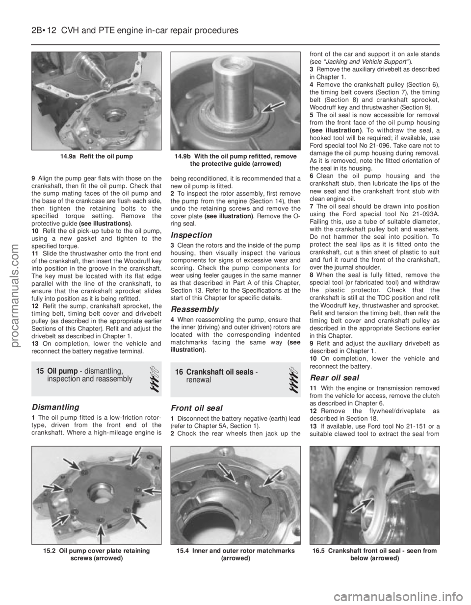
9Align the pump gear flats with those on the
crankshaft, then fit the oil pump. Check that
the sump mating faces of the oil pump and
the base of the crankcase are flush each side,
then tighten the retaining bolts to the
specified torque setting. Remove the
protective guide (see illustrations) .
10 Refit the oil pick-up tube to the oil pump,
using a new gasket and tighten to the
specified torque.
11 Slide the thrustwasher onto the front end
of the crankshaft, then insert the Woodruff key
into position in the groove in the crankshaft.
The key must be located with its flat edge
parallel with the line of the crankshaft, to
ensure that the crankshaft sprocket slides
fully into position as it is being refitted.
12 Refit the sump, crankshaft sprocket, the
timing belt, timing belt cover and drivebelt
pulley (as described in the appropriate earlier
Sections of this Chapter). Refit and adjust the
drivebelt as described in Chapter 1.
13 On completion, lower the vehicle and
reconnect the battery negative terminal.
15 Oil pump - dismantling,
inspection and reassembly
3
Dismantling
1 The oil pump fitted is a low-friction rotor-
type, driven from the front end of the
crankshaft. Where a high-mileage engine is being reconditioned, it is recommended that a
new oil pump is fitted.
2
To inspect the rotor assembly, first remove
the pump from the engine (Section 14), then
undo the retaining screws and remove the
cover plate (see illustration) . Remove the O-
ring seal.
Inspection
3 Clean the rotors and the inside of the pump
housing, then visually inspect the various
components for signs of excessive wear and
scoring. Check the pump components for
wear using feeler gauges in the same manner
as that described in Part A of this Chapter,
Section 13. Refer to the Specifications at the
start of this Chapter for specific details.
Reassembly
4 When reassembling the pump, ensure that
the inner (driving) and outer (driven) rotors are
located with the corresponding indented
matchmarks facing the same way (see
illustration) .
16Crankshaft oil seals -
renewal
4
Front oil seal
1 Disconnect the battery negative (earth) lead
(refer to Chapter 5A, Section 1).
2 Chock the rear wheels then jack up the front of the car and support it on axle stands
(see
“Jacking and Vehicle Support” ).
3 Remove the auxiliary drivebelt as described
in Chapter 1.
4 Remove the crankshaft pulley (Section 6),
the timing belt covers (Section 7), the timing
belt (Section 8) and crankshaft sprocket,
Woodruff key and thrustwasher (Section 9).
5 The oil seal is now accessible for removal
from the front face of the oil pump housing
(see illustration) . To withdraw the seal, a
hooked tool will be required; if available, use
Ford special tool No 21-096. Take care not to
damage the oil pump housing during removal.
As it is removed, note the fitted orientation of
the seal in its housing.
6 Clean the oil pump housing and the
crankshaft stub, then lubricate the lips of the
new seal and the crankshaft front stub with
clean engine oil.
7 The oil seal should be drawn into position
using the Ford special tool No 21-093A.
Failing this, use a tube of suitable diameter,
with the crankshaft pulley bolt and washers.
Do not hammer the seal into position. To
protect the seal lips as it is fitted onto the
crankshaft, cut a thin sheet of plastic to suit
and furl it round the front of the crankshaft,
over the journal shoulder.
8 When the seal is fully fitted, remove the
special tool (or fabricated tool) and withdraw
the plastic protector. Check that the
crankshaft is still at the TDC position and refit
the Woodruff key, thrustwasher and sprocket.
Refit and tension the timing belt, then refit the
timing belt cover and crankshaft pulley as
described in the appropriate Sections earlier
in this Chapter.
9 Refit and adjust the auxiliary drivebelt as
described in Chapter 1.
10 On completion, lower the vehicle and
reconnect the battery.
Rear oil seal
11 With the engine or transmission removed
from the vehicle for access, remove the clutch
as described in Chapter 6.
12 Remove the flywheel/driveplate as
described in Section 18.
13 If available, use Ford tool No 21-151 or a
suitable clawed tool to extract the seal from
2B•12 CVH and PTE engine in-car repair procedures
16.5 Crankshaft front oil seal - seen from
below (arrowed)15.4 Inner and outer rotor matchmarks (arrowed)15.2 Oil pump cover plate retainingscrews (arrowed)
14.9b With the oil pump refitted, removethe protective guide (arrowed)14.9a Refit the oil pump
1595Ford Fiesta Remakeprocarmanuals.com
http://vnx.su
Page 86 of 296
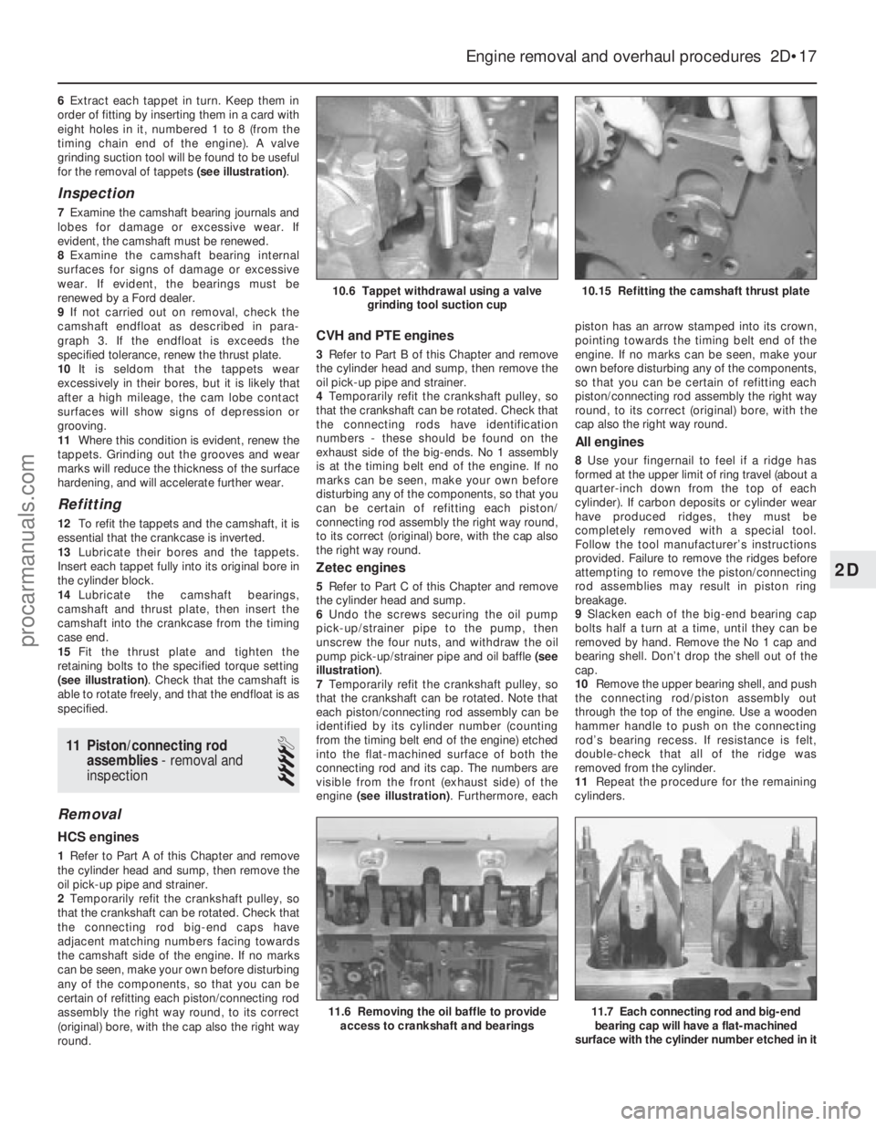
6Extract each tappet in turn. Keep them in
order of fitting by inserting them in a card with
eight holes in it, numbered 1 to 8 (from the
timing chain end of the engine). A valve
grinding suction tool will be found to be useful
for the removal of tappets (see illustration).
Inspection
7Examine the camshaft bearing journals and
lobes for damage or excessive wear. If
evident, the camshaft must be renewed.
8 Examine the camshaft bearing internal
surfaces for signs of damage or excessive
wear. If evident, the bearings must be
renewed by a Ford dealer.
9 If not carried out on removal, check the
camshaft endfloat as described in para-
graph 3. If the endfloat is exceeds the
specified tolerance, renew the thrust plate.
10 It is seldom that the tappets wear
excessively in their bores, but it is likely that
after a high mileage, the cam lobe contact
surfaces will show signs of depression or
grooving.
11 Where this condition is evident, renew the
tappets. Grinding out the grooves and wear
marks will reduce the thickness of the surface
hardening, and will accelerate further wear.
Refitting
12 To refit the tappets and the camshaft, it is
essential that the crankcase is inverted.
13 Lubricate their bores and the tappets.
Insert each tappet fully into its original bore in
the cylinder block.
14 Lubricate the camshaft bearings,
camshaft and thrust plate, then insert the
camshaft into the crankcase from the timing
case end.
15 Fit the thrust plate and tighten the
retaining bolts to the specified torque setting
(see illustration) . Check that the camshaft is
able to rotate freely, and that the endfloat is as
specified.
11 Piston/connecting rod
assemblies - removal and
inspection
4
Removal
HCS engines
1 Refer to Part A of this Chapter and remove
the cylinder head and sump, then remove the
oil pick-up pipe and strainer.
2 Temporarily refit the crankshaft pulley, so
that the crankshaft can be rotated. Check that
the connecting rod big-end caps have
adjacent matching numbers facing towards
the camshaft side of the engine. If no marks
can be seen, make your own before disturbing
any of the components, so that you can be
certain of refitting each piston/connecting rod
assembly the right way round, to its correct
(original) bore, with the cap also the right way
round.
CVH and PTE engines
3 Refer to Part B of this Chapter and remove
the cylinder head and sump, then remove the
oil pick-up pipe and strainer.
4 Temporarily refit the crankshaft pulley, so
that the crankshaft can be rotated. Check that
the connecting rods have identification
numbers - these should be found on the
exhaust side of the big-ends. No 1 assembly
is at the timing belt end of the engine. If no
marks can be seen, make your own before
disturbing any of the components, so that you
can be certain of refitting each piston/
connecting rod assembly the right way round,
to its correct (original) bore, with the cap also
the right way round.
Zetec engines
5 Refer to Part C of this Chapter and remove
the cylinder head and sump.
6 Undo the screws securing the oil pump
pick-up/strainer pipe to the pump, then
unscrew the four nuts, and withdraw the oil
pump pick-up/strainer pipe and oil baffle (see
illustration) .
7 Temporarily refit the crankshaft pulley, so
that the crankshaft can be rotated. Note that
each piston/connecting rod assembly can be
identified by its cylinder number (counting
from the timing belt end of the engine) etched
into the flat-machined surface of both the
connecting rod and its cap. The numbers are
visible from the front (exhaust side) of the
engine (see illustration) . Furthermore, each piston has an arrow stamped into its crown,
pointing towards the timing belt end of the
engine. If no marks can be seen, make your
own before disturbing any of the components,
so that you can be certain of refitting each
piston/connecting rod assembly the right way
round, to its correct (original) bore, with the
cap also the right way round.
All engines
8
Use your fingernail to feel if a ridge has
formed at the upper limit of ring travel (about a
quarter-inch down from the top of each
cylinder). If carbon deposits or cylinder wear
have produced ridges, they must be
completely removed with a special tool.
Follow the tool manufacturer’s instructions
provided. Failure to remove the ridges before
attempting to remove the piston/connecting
rod assemblies may result in piston ring
breakage.
9 Slacken each of the big-end bearing cap
bolts half a turn at a time, until they can be
removed by hand. Remove the No 1 cap and
bearing shell. Don’t drop the shell out of the
cap.
10 Remove the upper bearing shell, and push
the connecting rod/piston assembly out
through the top of the engine. Use a wooden
hammer handle to push on the connecting
rod’s bearing recess. If resistance is felt,
double- check that all of the ridge was
removed from the cylinder.
11 Repeat the procedure for the remaining
cylinders.
Engine removal and overhaul procedures 2D•17
10.15 Refitting the camshaft thrust plate10.6 Tappet withdrawal using a valve grinding tool suction cup
11.7 Each connecting rod and big-endbearing cap will have a flat-machined
surface with the cylinder number etched in it11.6 Removing the oil baffle to provide access to crankshaft and bearings
2D
1595Ford Fiesta Remakeprocarmanuals.com
http://vnx.su
Page 88 of 296
HCS engines
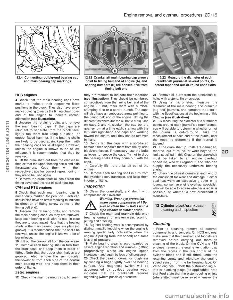
4Check that the main bearing caps have
marks to indicate their respective fitted
positions in the block. They also have arrow
marks pointing towards the timing chain cover
end of the engine to indicate correct
orientation (see illustration) .
5 Unscrew the retaining bolts, and remove
the main bearing caps. If the caps are
reluctant to separate from the block face,
lightly tap them free using a plastic- or
copper-faced hammer. If the bearing shells
are likely to be used again, keep them with
their bearing caps for safekeeping. However,
unless the engine is known to be of low
mileage, it is recommended that they be
renewed.
6 Lift the crankshaft out from the crankcase,
then extract the upper bearing shells and side
thrustwashers. Keep them with their
respective caps for correct repositioning if
they are to be used again.
7 Remove the crankshaft oil seals from the
timing cover and the rear oil seal housing.
CVH and PTE engines
8 Check that each main bearing cap is
numerically marked for position. Each cap
should also have an arrow marking to indicate
its direction of fitting (arrow points to the
timing belt end).
9 Unscrew the retaining bolts, and remove
the main bearing caps. As they are removed,
keep each bearing shell with its cap (in case
they are to used again). Note that the bearing
shells in the main bearing caps are plain (no
groove). It is recommended that the shells be
renewed, unless the engine is known to be of
low mileage.
10 Lift out the crankshaft from the crankcase.
11 Remove each bearing shell in turn from
the crankcase, and keep them in order of
fitting. Note that the upper shell halves are
grooved. Also remove the semi-circular
thrustwasher from each side of the central
main bearing web, and keep them in their
order of fitting.
Zetec engines
12 Check the main bearing caps, to see if they are marked to indicate their locations
(see illustration)
. They should be numbered
consecutively from the timing belt end of the
engine - if not, mark them with number-
stamping dies or a centre-punch. The caps
will also have an embossed arrow pointing to
the timing belt end of the engine. Noting the
different fasteners (for the oil baffle nuts) used
on caps 2 and 4, slacken the cap bolts a
quarter-turn at a time each, starting with the
left- and right-hand end caps and working
toward the centre, until they can be removed
by hand.
13 Gently tap the caps with a soft-faced
hammer, then separate them from the cylinder
block/crankcase. If necessary, use the bolts
as levers to remove the caps. Try not to drop
the bearing shells if they come out with the
caps.
14 Carefully lift the crankshaft out of the
engine.
15 Remove each bearing shell in turn from
the cylinder block/crankcase, and keep them
in order of fitting.
Inspection
16 Clean the crankshaft, and dry it with
compressed air if available.
Warning: Wear eye protection
when using compressed air! Be
sure to clean the oil holes with a
pipe cleaner or similar probe.
17 Check the main and crankpin (big-end)
bearing journals for uneven wear, scoring,
pitting and cracking.
18 Big-end bearing wear is accompanied by
distinct metallic knocking when the engine is
running (particularly noticeable when the
engine is pulling from low speed) and some
loss of oil pressure.
19 Main bearing wear is accompanied by
severe engine vibration and rumble - getting
progressively worse as engine speed
increases - and again by loss of oil pressure.
20 Check the bearing journal for roughness
by running a finger lightly over the bearing
surface. Any roughness (which will be
accompanied by obvious bearing wear)
indicates that the crankshaft requires
regrinding (where possible) or renewal. 21
Remove all burrs from the crankshaft oil
holes with a stone, file or scraper.
22 Using a micrometer, measure the
diameter of the main bearing and crankpin
(big-end) journals, and compare the results
with the Specifications at the beginning of this
Chapter (see illustration) .
23 By measuring the diameter at a number of
points around each journal’s circumference,
you will be able to determine whether or not
the journal is out-of-round. Take the
measurement at each end of the journal, near
the webs, to determine if the journal is
tapered.
24 If the crankshaft journals are damaged,
tapered, out-of-round, or worn beyond the
limits specified in this Chapter, the crankshaft
must be taken to an engine overhaul
specialist, who will regrind it, and who can
supply the necessary undersize bearing
shells.
25 Check the oil seal journals at each end of
the crankshaft for wear and damage. If either
seal has worn an excessive groove in its
journal, consult an engine overhaul specialist,
who will be able to advise whether a repair is
possible, or whether a new crankshaft is
necessary.
13 Cylinder block/crankcase -
cleaning and inspection
2
Cleaning
1 Prior to cleaning, remove all external
components and senders. On HCS engines,
make sure that the camshaft and tappets are
removed before carrying out thorough
cleaning of the block. On the CVH and PTE
engines, remove the engine ventilation cap
from the recess in the rear corner of the
cylinder block and if still fitted, undo the
retaining screw and withdraw the engine
speed sensor from the bellhousing face. On
Zetec engines, unbolt the piston-cooling oil
jets or blanking plugs (as applicable); note
that Ford state that the piston-cooling oil jets
(where fitted) must be renewed whenever the
Engine removal and overhaul procedures 2D•19
12.22 Measure the diameter of each
crankshaft journal at several points, to
detect taper and out-of-round conditions12.12 Crankshaft main bearing cap arrows point to timing belt end of engine (A), and
bearing numbers (B) are consecutive from timing belt end12.4 Connecting rod big-end bearing capand main bearing cap markings
2D
1595Ford Fiesta Remakeprocarmanuals.com
http://vnx.su
Page 161 of 296
1 General information,precautions and battery
disconnection
General information
The engine electrical system consists
mainly of the charging and starting systems.
Because of their engine-related functions,
these components are covered separately
from the body electrical devices such as the
lights, instruments, etc (which are covered in
Chapter 12). Information on the ignition
system is covered in Part B of this Chapter.
The electrical system is of the 12-volt
negative earth type. The battery is of the low maintenance or
“maintenance-free” (sealed for life) type and is
charged by the alternator, which is belt-driven
from the crankshaft pulley. The starter motor is of the pre-engaged
type incorporating an integral solenoid. On
starting, the solenoid moves the drive pinion
into engagement with the flywheel ring gear
before the starter motor is energised. Once
the engine has started, a one-way clutch
prevents the motor armature being driven by
the engine until the pinion disengages from
the flywheel.
Precautions
Further details of the various systems are
given in the relevant Sections of this Chapter.
While some repair procedures are given, the
usual course of action is to renew the
component concerned. The owner whose
interest extends beyond mere component
renewal should obtain a copy of the
“Automobile Electrical & Electronic Systems
Manual” , available from the publishers of this
manual. It is necessary to take extra care when
working on the electrical system to avoid
damage to semi-conductor devices (diodes
and transistors), and to avoid the risk of
personal injury. In addition to the precautions
given in “Safety first!” at the beginning of this
manual, observe the following when working
on the system:
Always remove rings, watches, etc before
working on the electrical system. Even with
the battery disconnected, capacitive
discharge could occur if a component’s live
terminal is earthed through a metal object.
This could cause a shock or nasty burn. Do not reverse the battery connections.
Components such as the alternator, electronic
control units, or any other components having
semi-conductor circuitry could be irreparably
damaged. If the engine is being started using jump
leads and a slave battery, connect the
batteries positive-to-positive and negative-to-
negative (see “Jump starting” ). This also
applies when connecting a battery charger.
Never disconnect the battery terminals, the
alternator, any electrical wiring or any test instruments when the engine is running.
Do not allow the engine to turn the
alternator when the alternator is not
connected. Never “test” for alternator output by
“flashing” the output lead to earth.
Never use an ohmmeter of the type
incorporating a hand-cranked generator for
circuit or continuity testing.
Always ensure that the battery negative lead
is disconnected when working on the
electrical system. Before using electric-arc welding
equipment on the car, disconnect the battery,
alternator and components such as the fuel
injection/ignition electronic control unit to
protect them from the risk of damage.
Battery disconnection
Several systems fitted to the vehicle require
battery power to be available at all times, either
to ensure that their continued operation (such as
the clock) or to maintain control unit memories
(such as that in the engine management
system’s ECU) which would be wiped if the
battery were to be disconnected. Whenever the
battery is to be disconnected therefore, first note
the following, to ensure that there are no
unforeseen consequences of this action:
a) First, on any vehicle with central locking, it is a wise precaution to remove the key
from the ignition, and to keep it with you,
so that it does not get locked in, if the
central locking should engage accidentally
when the battery is reconnected.
b) On cars equipped with an engine
management system, the system’s ECU will
lose the information stored in its memory -
referred to by Ford as the “KAM” (Keep-
Alive Memory) - when the battery is
disconnected. This includes idling and
operating values, and any fault codes
detected - in the case of the fault codes, if
it is thought likely that the system has
developed a fault for which the
corresponding code has been logged, the
vehicle must be taken to a Ford dealer for
the codes to be read, using the special
diagnostic equipment necessary for this.
Whenever the battery is disconnected, the
information relating to idle speed control
and other operating values will have to be
re-programmed into the unit’s memory.
The ECU does this by itself, but until then,
there may be surging, hesitation, erratic idle
and a generally inferior level of
performance. To allow the ECU to relearn
these values, start the engine and run it as
close to idle speed as possible until it
reaches its normal operating temperature,
then run it for approximately two minutes at
1200 rpm. Next, drive the vehicle as far as
necessary - approximately 5 miles of varied
driving conditions is usually sufficient - to
complete the relearning process.
c) If the battery is disconnected while the alarm system is armed or activated, the
alarm will remain in the same state when the battery is reconnected. The same
applies to the engine immobiliser system
(where fitted).
d) If a Ford “Keycode” audio unit is fitted,
and the unit and/or the battery is
disconnected, the unit will not function
again on reconnection until the correct
security code is entered. Details of this
procedure, which varies according to the
unit and model year, are given in the
“Ford Audio Systems Operating Guide”
supplied with the vehicle when new, with
the code itself being given in a “Radio
Passport” and/or a “Keycode Label” at
the same time. Ensure you have the
correct code before you disconnect the
battery. For obvious security reasons, the
procedure is not given in this manual. If
you do not have the code or details of the
correct procedure, but can supply proof
of ownership and a legitimate reason for
wanting this information, the vehicle’s
selling dealer may be able to help.
Devices known as “memory-savers” (or
“code-savers”) can be used to avoid some of
the above problems. Precise details vary
according to the device used. Typically, it is
plugged into the cigarette lighter, and is
connected by its own wires to a spare battery;
the vehicle’s own battery is then disconnected
from the electrical system, leaving the
“memory-saver” to pass sufficient current to
maintain audio unit security codes and ECU
memory values, and also to run permanently-
live circuits such as the clock, all the while
isolating the battery in the event of a short-
circuit occurring while work is carried out.
Warning: Some of these devices
allow a considerable amount of
current to pass, which can mean
that many of the vehicle’s
systems are still operational when the
main battery is disconnected. If a
“memory-saver” is used, ensure that the
circuit concerned is actually “dead” before
carrying out any work on it!
2 Electrical fault finding - general information
Refer to Chapter 12.
3 Battery -testing and charging
1
Standard and low maintenance
battery - testing
1If the vehicle covers a small annual mileage,
it is worthwhile checking the specific gravity
of the electrolyte every three months to
determine the state of charge of the battery.
Use a hydrometer to make the check and
compare the results with the following table.
5A•2 Starting and charging systems
1595Ford Fiesta Remakeprocarmanuals.com
http://vnx.su