1989 FORD FIESTA run flat
[x] Cancel search: run flatPage 12 of 296
4 Auxiliary drivebelt check andrenewal
2
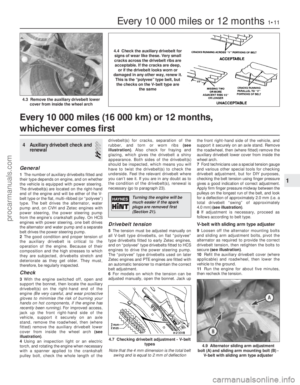
General
1The number of auxiliary drivebelts fitted and
their type depends on engine, and on whether
the vehicle is equipped with power steering.
The drivebelt(s) are located on the right-hand
end of the engine and will be either of the V-
belt type or the flat, multi-ribbed (or “polyvee”)
type. The belt drives the alternator, water
pump and, on CVH and Zetec engines with
power steering, the power steering pump
from the engine’s crankshaft pulley. On HCS
engines with power steering, one belt drives
the alternator and water pump and a separate
belt drives the power steering pump.
2 The good condition and proper tension of
the auxiliary drivebelt is critical to the
operation of the engine. Because of their
composition and the high stresses to which
they are subjected, drivebelts stretch and
deteriorate as they get older. They must,
therefore, be regularly inspected.
Check
3 With the engine switched off, open and
support the bonnet, then locate the auxiliary
drivebelt(s) on the right-hand end of the
engine (Be very careful, and wear protective
gloves to minimise the risk of burning your
hands on hot components, if the engine has
recently been running). For improved access,
jack up the front right-hand side of the
vehicle, support it securely on an axle
stand, remove the roadwheel, then (where
fitted) remove the auxiliary drivebelt lower
cover from inside the wheel arch (see
illustration) .
4 Using an inspection light or an electric
torch, and rotating the engine when necessary
with a spanner applied to the crankshaft
pulley bolt, check the whole length of the drivebelt(s) for cracks, separation of the
rubber, and torn or worn ribs
(see
illustration) . Also check for fraying and
glazing, which gives the drivebelt a shiny
appearance. Both sides of the drivebelt(s)
should be inspected, which means you will
have to twist the drivebelt(s) to check the
underside. Feel the relevant drivebelt where
you can’t see it. If you are in any doubt as to
the condition of the drivebelt(s), renewal is
necessary (go to paragraph 23).
Drivebelt tension
5 The tension must be adjusted manually on
all V-belt type drivebelts, on flat “polyvee”
type drivebelts fitted to early Zetec engines,
and on “polyvee” type drivebelts fitted to HCS
engines to drive the power steering pump.
The “polyvee” type drivebelts used on later
Zetec engines and PTE engines are fitted with
an automatic tensioner to maintain the correct
belt adjustment.
6 For models on which the tension can be
adjusted manually, open the bonnet. Jack up the front right-hand side of the vehicle, and
support it securely on an axle stand. Remove
the roadwheel, then (where fitted) remove the
auxiliary drivebelt lower cover from inside the
wheel arch.
7
Ford technicians use a special tension gauge
and various other special tools for checking
drivebelt adjustment, but for DIY purposes,
checking the belt tension using finger pressure
gives a good indication of correct adjustment.
Apply firm finger pressure midway between the
pulleys on the longest run of the belt, and look
for a deflection of approximately 2.0 mm (i.e. a
total drivebelt “swing” of approximately
4.0 mm) (see illustration) .
8 If adjustment is necessary, proceed as
follows according to belt type.
V-belt with sliding arm type adjuster
9 Loosen off the alternator mounting bolts
and sliding arm adjustment bolts, pivot the
alternator as required to provide the correct
drivebelt tension, then retighten the bolts to
secure (see illustration) .
10 Refit the auxiliary drivebelt cover (where
applicable) and roadwheel, then lower the
vehicle to the ground.
11 Run the engine for about five minutes,
then recheck the tension.
Every 10 000 miles (16 000 km) or 12 months,
whichever comes first
Every 10 000 miles or 12 months1•11
4.9 Alternator sliding arm adjustment
bolt (A) and sliding arm mounting bolt (B) - V-belt with sliding arm type adjuster
4.7 Checking drivebelt adjustment - V-belt types
Note that the 4 mm dimension is the total belt swing and is equal to 2 mm of deflection
4.3 Remove the auxiliary drivebelt lower cover from inside the wheel arch
1
1595Ford Fiesta Remake
4.4 Check the auxiliary drivebelt forsigns of wear like these. Very small
cracks across the drivebelt ribs are acceptable. If the cracks are deep, or if the drivebelt looks worn or
damaged in any other way, renew it. This is the “polyvee” type belt, butthe checks on the V-belt type are the same
Turning the engine will be
much easier if the spark
plugs are removed first
(Section 21).
procarmanuals.com
http://vnx.su
Page 13 of 296
V-belt and flat “polyvee” type
drivebelt with rack-and-pinion type
adjuster
12Loosen off the alternator mounting bolts
and the adjusting arm mounting bolt. Slacken
the pinion central locking bolt, and turn the
pinion nut as required to take up the tension
of the drivebelt. Hold it at the required setting,
and tighten the central bolt securely to lock
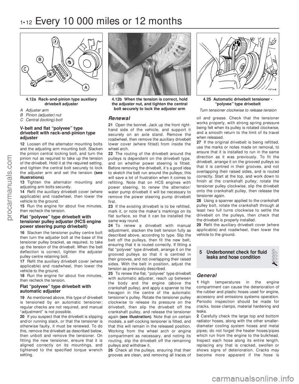
the adjuster arm and set the tension (see
illustrations) .
13 Tighten the alternator mounting and
adjusting arm bolts securely.
14 Refit the auxiliary drivebelt cover (where
applicable) and roadwheel, then lower the
vehicle to the ground.
15 Run the engine for about five minutes,
then recheck the tension.
Flat “polyvee” type drivebelt with
tensioner pulley adjuster (HCS engine
power steering pump drivebelt)
16 Slacken the tensioner pulley centre bolt
then turn the adjuster bolt at the base of the
tensioner pulley bracket, as required, to take
up the tension of the drivebelt. When the belt
deflection is correct, tighten the adjuster
pulley centre retaining bolt.
17 Refit the auxiliary drivebelt cover (where
applicable) and roadwheel, then lower the
vehicle to the ground.
18 Run the engine for about five minutes,
then recheck the tension.
Flat “polyvee” type drivebelt with
automatic adjuster
19 As mentioned above, this type of drivebelt
is tensioned by an automatic tensioner;
regular checks are not required, and manual
“adjustment” is not possible.
20 If you suspect that the drivebelt is slipping
and/or running slack, or that the tensioner is
otherwise faulty, it must be renewed. To do
this, remove the drivebelt as described below,
then unbolt and remove the tensioner. On
fitting the new tensioner, ensure that it is
aligned correctly on its mountings, and
tightened to the specified torque wrench
setting.
Renewal
21 Open the bonnet. Jack up the front right-
hand side of the vehicle, and support it
securely on an axle stand. Remove the
roadwheel, then remove the auxiliary drivebelt
lower cover (where fitted) from inside the
wheel arch.
22 The routing of the drivebelt around the
pulleys is dependent on the drivebelt type,
and on whether power steering is fitted.
Before removing the drivebelt, it’s a good idea
to sketch the belt run around the pulleys; this
will save a lot of frustration when it comes to
refitting. Note that on HCS engines with
power steering, to renew the alternator/
water pump drivebelt it will be necessary to
remove the power steering pump drivebelt
first.
23 If the existing drivebelt is to be refitted,
mark it, or note the maker’s markings on its
flat surface, so that it can be installed the
same way round.
24 To renew a drivebelt with manual
adjustment, slacken the belt tension fully as
described above, according to type. Slip the
belt off the pulleys, then fit the new belt,
ensuring that it is routed correctly. If fitting a
flat “polyvee” type drivebelt, arrange it on the
grooved pulleys so that it is centred in
their grooves, and not overlapping their raised
sides. With the belt in position, adjust the
tension as previously described.
25 To renew the flat, “polyvee” type drivebelt
with automatic adjuster, reach up between
the body and the engine (above the
crankshaft pulley), and apply a spanner to the
hexagon in the centre of the automatic
tensioner’s pulley. Rotate the tensioner pulley
clockwise to release its pressure on the
drivebelt, then slip the drivebelt off the
crankshaft pulley, and release the tensioner
again (see illustration) . Note that on certain
models, a self-cocking tensioner is fitted, and
that this will remain in the released position.
Working from the wheel arch or engine
compartment as necessary, and noting its
routing, slip the drivebelt off the remaining
pulleys and withdraw it.
26 Check all the pulleys, ensuring that their
grooves are clean, and removing all traces of oil and grease. Check that the tensioner
works properly, with strong spring pressure
being felt when its pulley is rotated clockwise,
and a smooth return to the limit of its travel
when released.
27
If the original drivebelt is being refitted,
use the marks or notes made on removal, to
ensure that it is installed to run in the same
direction as it was previously. To fit the
drivebelt, arrange it on the grooved pulleys so
that it is centred in their grooves, and not
overlapping their raised sides, and is routed
correctly. Start at the top, and work down to
finish at the crankshaft pulley; rotate the
tensioner pulley clockwise, slip the drivebelt
onto the crankshaft pulley, then release the
tensioner again.
28 Using a spanner applied to the crankshaft
pulley bolt, rotate the crankshaft through at
least two full turns clockwise to settle the
drivebelt on the pulleys, then check that
the drivebelt is properly installed.
29 Refit the auxiliary drivebelt cover (where
applicable) and roadwheel, then lower the
vehicle to the ground.
5 Underbonnet check for fluid leaks and hose condition
1
General
1High temperatures in the engine
compartment can cause the deterioration of
the rubber and plastic hoses used for engine,
accessory and emissions systems operation.
Periodic inspection should be made for
cracks, loose clamps, material hardening and
leaks.
2 Carefully check the large top and bottom
radiator hoses, along with the other smaller-
diameter cooling system hoses and metal
pipes; do not forget the heater hoses/pipes
which run from the engine to the bulkhead.
Inspect each hose along its entire length,
replacing any that is cracked, swollen or
shows signs of deterioration. Cracks may
become more apparent if the hose is
1•12Every 10 000 miles or 12 months
4.25 Automatic drivebelt tensioner - “polyvee” type drivebelt
Turn tensioner clockwise to release tension4.12b When the tension is correct, hold
the adjuster nut, and tighten the central bolt securely to lock the adjuster arm4.12a Rack-and-pinion type auxiliary drivebelt adjuster
A Adjuster arm
B Pinion (adjuster) nut
C Central (locking) bolt
1595Ford Fiesta Remakeprocarmanuals.com
http://vnx.su
Page 15 of 296
connections - remake the connections or
renew the leads if a fault is found. Use the
same techniques to ensure that all earth
points in the engine compartment provide
good electrical contact through clean, metal-
to-metal joints, and that all are securely
fastened. (In addition to the earth connection
at the engine lifting eye, and that from the
transmission to the body/battery, there are
others in various places, so check carefully).
8Refer to Section 21 for details of spark plug
(HT) lead checks.
7 Valve clearance adjustment
2
Refer to Chapter 2, Part A.
8 Manual transmission oil level check
1
1The manual transmission does not have a
dipstick. To check the oil level, raise the
vehicle and support it securely on axle stands,
making sure that the vehicle is level. On the
lower front side of the transmission housing,
you will see the filler/level plug. Unscrew and
remove it - an Allen key or bit will probably be
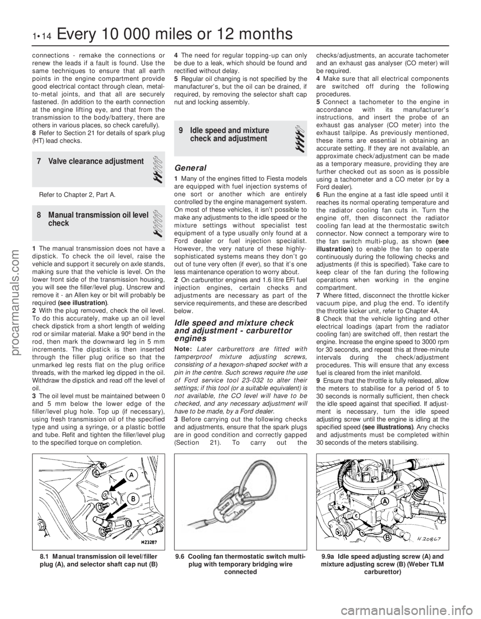
required (see illustration) .
2 With the plug removed, check the oil level.
To do this accurately, make up an oil level
check dipstick from a short length of welding
rod or similar material. Make a 90º bend in the
rod, then mark the downward leg in 5 mm
increments. The dipstick is then inserted
through the filler plug orifice so that the
unmarked leg rests flat on the plug orifice
threads, with the marked leg dipped in the oil.
Withdraw the dipstick and read off the level of
oil.
3 The oil level must be maintained between 0
and 5 mm below the lower edge of the
filler/level plug hole. Top up (if necessary),
using fresh transmission oil of the specified
type and using a syringe, or a plastic bottle
and tube. Refit and tighten the filler/level plug
to the specified torque on completion. 4
The need for regular topping-up can only
be due to a leak, which should be found and
rectified without delay.
5 Regular oil changing is not specified by the
manufacturer’s, but the oil can be drained, if
required, by removing the selector shaft cap
nut and locking assembly.
9 Idle speed and mixture check and adjustment
4
General
1Many of the engines fitted to Fiesta models
are equipped with fuel injection systems of
one sort or another which are entirely
controlled by the engine management system.
On most of these vehicles, it isn’t possible to
make any adjustments to the idle speed or the
mixture settings without specialist test
equipment of a type usually only found at a
Ford dealer or fuel injection specialist.
However, the very nature of these highly-
sophisticated systems means they don’t go
out of tune very often (if ever), so that it’s one
less maintenance operation to worry about.
2 On carburettor engines and 1.6 litre EFi fuel
injection engines, certain checks and
adjustments are necessary as part of the
service requirements, and these are described
below.
Idle speed and mixture check
and adjustment - carburettor
engines
Note: Later carburettors are fitted with
tamperproof mixture adjusting screws,
consisting of a hexagon-shaped socket with a
pin in the centre. Such screws require the use
of Ford service tool 23-032 to alter their
settings; if this tool (or a suitable equivalent) is
not available, the CO level will have to be
checked, and any necessary adjustment will
have to be made, by a Ford dealer.
3 Before carrying out the following checks
and adjustments, ensure that the spark plugs
are in good condition and correctly gapped
(Section 21). To carry out the checks/adjustments, an accurate tachometer
and an exhaust gas analyser (CO meter) will
be required.
4
Make sure that all electrical components
are switched off during the following
procedures.
5 Connect a tachometer to the engine in
accordance with its manufacturer’s
instructions, and insert the probe of an
exhaust gas analyser (CO meter) into the
exhaust tailpipe. As previously mentioned,
these items are essential in obtaining an
accurate setting. If they are not available, an
approximate check/adjustment can be made
as a temporary measure, providing they are
further checked out as soon as is possible
using a tachometer and a CO meter (or by a
Ford dealer).
6 Run the engine at a fast idle speed until it
reaches its normal operating temperature and
the radiator cooling fan cuts in. Turn the
engine off, then disconnect the radiator
cooling fan lead at the thermostatic switch
connector. Now connect a temporary wire to
the fan switch multi-plug, as shown (see
illustration) to enable the fan to operate
continuously during the following checks and
adjustments (if this is specified). Take care to
keep clear of the fan during the following
operations when working in the engine
compartment.
7 Where fitted, disconnect the throttle kicker
vacuum pipe, and plug the end. To identify
the throttle kicker unit, refer to Chapter 4A.
8 Check that the vehicle lighting and other
electrical loadings (apart from the radiator
cooling fan) are switched off, then restart the
engine. Increase the engine speed to 3000 rpm
for 30 seconds, and repeat this at three-minute
intervals during the check/adjustment
procedures. This will ensure that any excess
fuel is cleared from the inlet manifold.
9 Ensure that the throttle is fully released, allow
the meters to stabilise for a period of 5 to
30 seconds is normally sufficient, then check
the idle speed against that specified. If adjust-
ment is necessary, turn the idle speed
adjusting screw until the engine is idling at the
specified speed (see illustrations) . Any checks
and adjustments must be completed within
30 seconds of the meters stabilising.
1•14Every 10 000 miles or 12 months
9.9a Idle speed adjusting screw (A) and
mixture adjusting screw (B) (Weber TLM
carburettor)9.6 Cooling fan thermostatic switch multi-plug with temporary bridging wire
connected8.1 Manual transmission oil level/filler
plug (A), and selector shaft cap nut (B)
1595Ford Fiesta Remakeprocarmanuals.com
http://vnx.su
Page 18 of 296
point at the engine to the end of the tailpipe.
Ideally, this should be done on a hoist, where
unrestricted access is available; if a hoist is
not available, raise and support the vehicle on
axle stands.
2Check the pipes and connections for
evidence of leaks, severe corrosion, or
damage. Make sure that all brackets and
rubber mountings are in good condition, and
tight; if any of the mountings are to be
renewed, ensure that the replacements are of
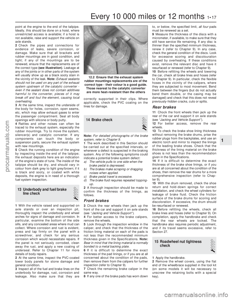
the correct type (see illustration) . Leakage at
any of the joints or in other parts of the system
will usually show up as a black sooty stain in
the vicinity of the leak. Note: Exhaust sealants
should not be used on any part of the exhaust
system upstream of the catalytic converter -
even if the sealant does not contain additives
harmful to the converter, pieces of it may
break off and foul the element, causing local
overheating.
3 At the same time, inspect the underside of
the body for holes, corrosion, open seams,
etc, which may allow exhaust gases to enter
the passenger compartment. Seal all body
openings with silicone or body putty.
4 Rattles and other noises can often be
traced to the exhaust system, especially the
rubber mountings. Try to move the system,
silencer(s) and catalytic converter. If any
components can touch the body or
suspension parts, secure the exhaust system
with new mountings.
5 Check the running condition of the engine
by inspecting inside the end of the tailpipe;
the exhaust deposits here are an indication
of the engine’s state of tune. The inside of the
tailpipe should be dry, and should vary in
colour from dark grey to light grey/brown; if it
is black and sooty, or coated with white
deposits, the engine is in need of a thorough
fuel system inspection.
13 Underbody and fuel/brake line check
1
1With the vehicle raised and supported on
axle stands or over an inspection pit,
thoroughly inspect the underbody and wheel
arches for signs of damage and corrosion. In
particular, examine the bottom of the side
sills, and any concealed areas where mud can
collect. Where corrosion and rust is evident,
press and tap firmly on the panel with a
screwdriver, and check for any serious
corrosion which would necessitate repairs. If
the panel is not seriously corroded, clean
away the rust, and apply a new coating of
underseal. Refer to Chapter 11 for more
details of body repairs.
2 At the same time, inspect the PVC-coated
lower body panels for stone damage and
general condition.
3 Inspect all of the fuel and brake lines on the
underbody for damage, rust, corrosion and
leakage. Also make sure that they are correctly supported in their clips. Where
applicable, check the PVC coating on the
lines for damage.
14 Brake check
2
Note:
For detailed photographs of the brake
system, refer to Chapter 9.
1 The work described in this Section should
be carried out at the specified intervals, or
whenever a defect is suspected in the braking
system. Any of the following symptoms could
indicate a potential brake system defect:
a) The vehicle pulls to one side when the brake pedal is depressed.
b) The brakes make scraping or dragging
noises when applied.
c) Brake pedal travel is excessive.
d) The brake fluid requires repeated topping-
up.
2 A thorough inspection should be made to
confirm the thickness of the linings, as
follows.
Front brakes
3 Chock the rear wheels then jack up the
front of the car and support it on axle stands
(see “Jacking and Vehicle Support” ).
4 For better access to the brake calipers,
remove the wheels.
5 Look through the inspection window in the
caliper, and check that the thickness of the
friction lining material on each of the pads is
not less than the recommended minimum
thickness given in the Specifications. Note:
Bear in mind that the lining material is normally
bonded to a metal backing plate.
6 If it is difficult to determine the exact
thickness of the pad linings, or if you are at all
concerned about the condition of the pads,
then remove them from the calipers for further
inspection (refer to Chapter 9).
7 Check the remaining brake caliper in the
same way.
8 If any one of the brake pads has worn down to, or below, the specified limit,
all fourpads
must be renewed as a set.
9 Measure the thickness of the discs with a
micrometer, if available, to make sure that they
still have service life remaining. If any disc is
thinner than the specified minimum thickness,
renew it (refer to Chapter 9). In any case,
check the general condition of the discs. Look
for excessive scoring and discolouration
caused by overheating. If these conditions
exist, remove the relevant disc and have it
resurfaced or renewed (refer to Chapter 9).
10 Before refitting the wheels and lowering
the car, check all brake lines and hoses (refer
to Chapter 9). In particular, check the flexible
hoses in the vicinity of the calipers, where
they are subjected to most movement. Bend
them between the fingers (but do not actually
bend them double, or the casing may be
damaged) and check that this does not reveal
previously-hidden cracks, cuts or splits.
Rear brakes
11 Chock the front wheels then jack up the
rear of the car and support it on axle stands
(see “Jacking and Vehicle Support” ).
12 For better access, remove the rear
wheels.
13 To check the brake shoe lining thickness
without removing the brake drums, prise the
rubber plugs from the backplates, and use an
electric torch and mirror to inspect the linings
of the leading brake shoes. Check that the
thickness of the lining material on the brake
shoes is not less than the recommendation
given in the Specifications.
14 If it is difficult to determine the exact
thickness of the brake shoe linings, or if you
are at all concerned about the condition of the
shoes, then remove the rear drums for a more
comprehensive inspection (refer to Chap-
ter 9).
15 With the drum removed, check the shoe
return and hold-down springs for correct
installation, and check the wheel cylinders for
leakage of brake fluid. Check the friction
surface of the brake drums for scoring and
discoloration. If excessive, the drum should
be resurfaced or renewed.
16 Before refitting the wheels, check all
brake lines and hoses (refer to Chapter 9). On
completion, apply the handbrake and check
that the rear wheels are locked. The
handbrake also requires periodic adjustment,
and if its travel seems excessive, refer to
Section 27.
15 Roadwheel nut tightness check
1
1Apply the handbrake.
2 Remove the wheel covers, using the flat
end of the wheelbrace supplied in the tool kit
(on some models it will be necessary to
unscrew the retaining bolts with a special
key).
Every 10 000 miles or 12 months1•17
12.2 Ensure that the exhaust system
rubber mountings replacements are of the correct type - their colour is a good guide. Those nearest to the catalytic converterare more heat-resistant than the others
1
1595Ford Fiesta Remakeprocarmanuals.com
http://vnx.su
Page 32 of 296
8Reassemble in the reverse order of
dismantling. Make sure that the “flat” on the
rear end of the rocker shaft is to the same side
as the rocker arm adjusting screws (closest to
the thermostat end of the cylinder head when
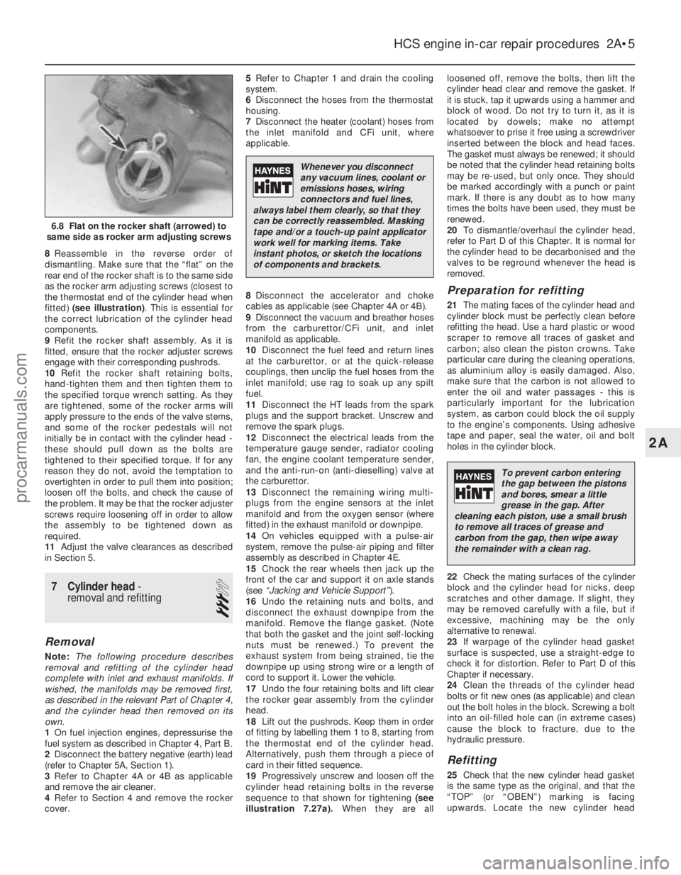
fitted) (see illustration) . This is essential for
the correct lubrication of the cylinder head
components.
9 Refit the rocker shaft assembly. As it is
fitted, ensure that the rocker adjuster screws
engage with their corresponding pushrods.
10 Refit the rocker shaft retaining bolts,
hand-tighten them and then tighten them to
the specified torque wrench setting. As they
are tightened, some of the rocker arms will
apply pressure to the ends of the valve stems,
and some of the rocker pedestals will not
initially be in contact with the cylinder head -
these should pull down as the bolts are
tightened to their specified torque. If for any
reason they do not, avoid the temptation to
overtighten in order to pull them into position;
loosen off the bolts, and check the cause of
the problem. It may be that the rocker adjuster
screws require loosening off in order to allow
the assembly to be tightened down as
required.
11 Adjust the valve clearances as described
in Section 5.
7 Cylinder head -
removal and refitting
3
Removal
Note: The following procedure describes
removal and refitting of the cylinder head
complete with inlet and exhaust manifolds. If
wished, the manifolds may be removed first,
as described in the relevant Part of Chapter 4,
and the cylinder head then removed on its
own.
1 On fuel injection engines, depressurise the
fuel system as described in Chapter 4, Part B.
2 Disconnect the battery negative (earth) lead
(refer to Chapter 5A, Section 1).
3 Refer to Chapter 4A or 4B as applicable
and remove the air cleaner.
4 Refer to Section 4 and remove the rocker
cover. 5
Refer to Chapter 1 and drain the cooling
system.
6 Disconnect the hoses from the thermostat
housing.
7 Disconnect the heater (coolant) hoses from
the inlet manifold and CFi unit, where
applicable.
8 Disconnect the accelerator and choke
cables as applicable (see Chapter 4A or 4B).
9 Disconnect the vacuum and breather hoses
from the carburettor/CFi unit, and inlet
manifold as applicable.
10 Disconnect the fuel feed and return lines
at the carburettor, or at the quick-release
couplings, then unclip the fuel hoses from the
inlet manifold; use rag to soak up any spilt
fuel.
11 Disconnect the HT leads from the spark
plugs and the support bracket. Unscrew and
remove the spark plugs.
12 Disconnect the electrical leads from the
temperature gauge sender, radiator cooling
fan, the engine coolant temperature sender,
and the anti-run-on (anti-dieselling) valve at
the carburettor.
13 Disconnect the remaining wiring multi-
plugs from the engine sensors at the inlet
manifold and from the oxygen sensor (where
fitted) in the exhaust manifold or downpipe.
14 On vehicles equipped with a pulse-air
system, remove the pulse-air piping and filter
assembly as described in Chapter 4E.
15 Chock the rear wheels then jack up the
front of the car and support it on axle stands
(see “Jacking and Vehicle Support” ).
16 Undo the retaining nuts and bolts, and
disconnect the exhaust downpipe from the
manifold. Remove the flange gasket. (Note
that both the gasket and the joint self-locking
nuts must be renewed.) To prevent the
exhaust system from being strained, tie the
downpipe up using strong wire or a length of
cord to support it. Lower the vehicle.
17 Undo the four retaining bolts and lift clear
the rocker gear assembly from the cylinder
head.
18 Lift out the pushrods. Keep them in order
of fitting by labelling them 1 to 8, starting from
the thermostat end of the cylinder head.
Alternatively, push them through a piece of
card in their fitted sequence.
19 Progressively unscrew and loosen off the
cylinder head retaining bolts in the reverse
sequence to that shown for tightening (see
illustration 7.27a). When they are all loosened off, remove the bolts, then lift the
cylinder head clear and remove the gasket. If
it is stuck, tap it upwards using a hammer and
block of wood. Do not try to turn it, as it is
located by dowels; make no attempt
whatsoever to prise it free using a screwdriver
inserted between the block and head faces.
The gasket must always be renewed; it should
be noted that the cylinder head retaining bolts
may be re-used, but only once. They should
be marked accordingly with a punch or paint
mark. If there is any doubt as to how many
times the bolts have been used, they must be
renewed.
20
To dismantle/overhaul the cylinder head,
refer to Part D of this Chapter. It is normal for
the cylinder head to be decarbonised and the
valves to be reground whenever the head is
removed.
Preparation for refitting
21 The mating faces of the cylinder head and
cylinder block must be perfectly clean before
refitting the head. Use a hard plastic or wood
scraper to remove all traces of gasket and
carbon; also clean the piston crowns. Take
particular care during the cleaning operations,
as aluminium alloy is easily damaged. Also,
make sure that the carbon is not allowed to
enter the oil and water passages - this is
particularly important for the lubrication
system, as carbon could block the oil supply
to the engine’s components. Using adhesive
tape and paper, seal the water, oil and bolt
holes in the cylinder block.
22 Check the mating surfaces of the cylinder
block and the cylinder head for nicks, deep
scratches and other damage. If slight, they
may be removed carefully with a file, but if
excessive, machining may be the only
alternative to renewal.
23 If warpage of the cylinder head gasket
surface is suspected, use a straight-edge to
check it for distortion. Refer to Part D of this
Chapter if necessary.
24 Clean the threads of the cylinder head
bolts or fit new ones (as applicable) and clean
out the bolt holes in the block. Screwing a bolt
into an oil-filled hole can (in extreme cases)
cause the block to fracture, due to the
hydraulic pressure.
Refitting
25 Check that the new cylinder head gasket
is the same type as the original, and that the
“TOP” (or “OBEN”) marking is facing
upwards. Locate the new cylinder head
HCS engine in-car repair procedures 2A•5
6.8 Flat on the rocker shaft (arrowed) to
same side as rocker arm adjusting screws
2A
1595Ford Fiesta Remake
Whenever you disconnect
any vacuum lines, coolant or
emissions hoses, wiring
connectors and fuel lines,
always label them clearly, so that they
can be correctly reassembled. Masking
tape and/or a touch-up paint applicator
work well for marking items. Take
instant photos, or sketch the locations
of components and brackets.
To prevent carbon entering
the gap between the pistons
and bores, smear a little
grease in the gap. After
cleaning each piston, use a small brush
to remove all traces of grease and
carbon from the gap, then wipe away
the remainder with a clean rag.
procarmanuals.com
http://vnx.su
Page 52 of 296
its housing. If the seal housing is removed
from the rear face of the engine, the seal can
be removed as described in paragraph 18. As
it is removed, note the direction of fitting, and
take care not to damage the seal housing as
the seal is extracted.
14Clean the seal housing, the crankshaft
rear flange face, and the flywheel/driveplate
mating surfaces.
15 One of two possible methods may be
used to insert the new oil seal, depending on
the tools available.
16 If Ford special service tool No 21-095 is
available, lubricate the seal lips of the seal and
its running face on the crankshaft with clean
engine oil. Position the seal (correctly
orientated) into the special tool, then draw the
seal into the housing using two
flywheel/driveplate securing bolts so that the
seal is against the stop.
17 If the correct Ford service tool is not
available, it will be necessary to remove the oil
seal carrier housing. To do this, first remove
the sump as described in Section 13, then
unscrew the seal housing retaining bolts and
remove the housing from the rear face of the
crankcase.
18 Drive the old seal from the housing by
carefully tapping it from its aperture using a
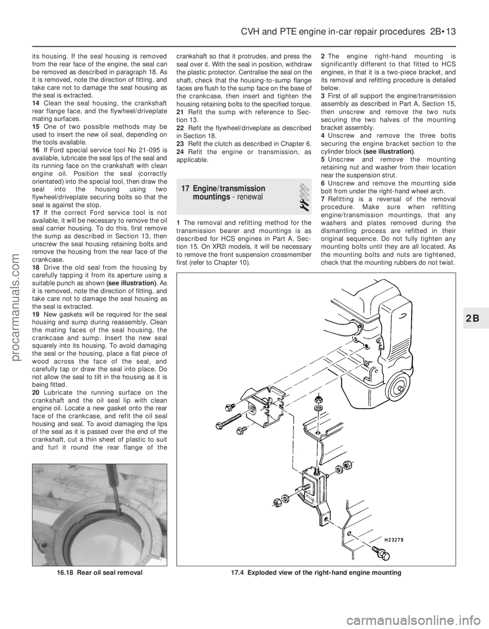
suitable punch as shown (see illustration). As
it is removed, note the direction of fitting, and
take care not to damage the seal housing as
the seal is extracted.
19 New gaskets will be required for the seal
housing and sump during reassembly. Clean
the mating faces of the seal housing, the
crankcase and sump. Insert the new seal
squarely into its housing. To avoid damaging
the seal or the housing, place a flat piece of
wood across the face of the seal, and
carefully tap or draw the seal into place. Do
not allow the seal to tilt in the housing as it is
being fitted.
20 Lubricate the running surface on the
crankshaft and the oil seal lip with clean
engine oil. Locate a new gasket onto the rear
face of the crankcase, and refit the oil seal
housing and seal. To avoid damaging the lips
of the seal as it is passed over the end of the
crankshaft, cut a thin sheet of plastic to suit
and furl it round the rear flange of the crankshaft so that it protrudes, and press the
seal over it. With the seal in position, withdraw
the plastic protector. Centralise the seal on the
shaft, check that the housing-to-sump flange
faces are flush to the sump face on the base of
the crankcase, then insert and tighten the
housing retaining bolts to the specified torque.
21
Refit the sump with reference to Sec-
tion 13.
22 Refit the flywheel/driveplate as described
in Section 18.
23 Refit the clutch as described in Chapter 6.
24 Refit the engine or transmission, as
applicable.
17 Engine/transmission mountings - renewal
2
1The removal and refitting method for the
transmission bearer and mountings is as
described for HCS engines in Part A, Sec-
tion 15. On XR2i models, it will be necessary
to remove the front suspension crossmember
first (refer to Chapter 10). 2
The engine right-hand mounting is
significantly different to that fitted to HCS
engines, in that it is a two-piece bracket, and
its removal and refitting procedure is detailed
below.
3 First of all support the engine/transmission
assembly as described in Part A, Section 15,
then unscrew and remove the two nuts
securing the two halves of the mounting
bracket assembly.
4 Unscrew and remove the three bolts
securing the engine bracket section to the
cylinder block (see illustration) .
5 Unscrew and remove the mounting
retaining nut and washer from their location
near the suspension strut.
6 Unscrew and remove the mounting side
bolt from under the right-hand wheel arch.
7 Refitting is a reversal of the removal
procedure. Make sure when refitting
engine/transmission mountings, that any
washers and plates removed during the
dismantling process are refitted in their
original sequence. Do not fully tighten any
mounting bolts until they are all located. As
the mounting bolts and nuts are tightened,
check that the mounting rubbers do not twist.
CVH and PTE engine in-car repair procedures 2B•13
17.4 Exploded view of the right-hand engine mounting16.18 Rear oil seal removal
2B
1595Ford Fiesta Remakeprocarmanuals.com
http://vnx.su
Page 91 of 296
necessary for reassembly of the engine are at
hand. In addition to all normal tools and
materials, jointing and thread locking
compound will be needed during engine
reassembly. For general-purpose applications,
it is recommended that Loctite 275 setting
sealer or Hylomar PL32M non-setting sealer
be used for joints where required, and
Loctite 270 for stud and bolt thread-locking.
For specific applications on Zetec engines,
Hylosil 102 for the cylinder block/crankcase-
to-sump/oil pump/oil seal carrier joints, and
Loctite 518 for the camshaft right-hand
bearing caps should be used. These are
recommended by, and obtained from, Ford
dealers. In all other cases, provided the
relevant mating surfaces are clean and flat,
new gaskets will be sufficient to ensure joints
are oil-tight. Do notuse any kind of silicone-
based sealant on any part of the fuel system or
inlet manifold, and neveruse exhaust sealants
upstream of the catalytic converter.
2 In order to save time and avoid problems,
engine reassembly can be carried out in the
following order (as applicable).
a) Engine ventilation cap (CVH and PTE engines).
b) Tappets and camshaft (HCS engines).
c) Crankshaft and main bearings.
d) Pistons and connecting rods.
e) Oil pump.
f) Sump.
g) Flywheel/driveplate.
h) Cylinder head.
i) Timing sprockets and chain/belt.
j) Engine external components.
3 Ensure that everything is clean prior to
reassembly. As mentioned previously, dirt and
metal particles can quickly destroy bearings
and result in major engine damage. Use clean
engine oil to lubricate during reassembly.
16 Piston rings - refitting
2
1Before installing new piston rings, check
the end gaps. Lay out each piston set with a
piston/connecting rod assembly, and keep them together as a matched set from now on.
2
Insert the top compression ring into the first
cylinder, and square it up with the cylinder
walls by pushing it in with the top of the
piston. The ring should be near the bottom of
the cylinder, at the lower limit of ring travel.
3 To measure the end gap, slip feeler gauges
between the ends of the ring, until a gauge
equal to the gap width is found. The feeler
gauge should slide between the ring ends
with a slight amount of drag. Compare the
measurement to the value given in the
Specifications in this Chapter; if the gap is
larger or smaller than specified, double-check to make sure you have the correct rings
before proceeding. If you are assessing the
condition of used rings, have the cylinder
bores checked and measured by a Ford
dealer or similar engine reconditioning
specialist, so that you can be sure of exactly
which component is worn, and seek advice as
to the best course of action to take.
4 If the end gap is still too small, it must be
opened up by careful filing of the ring ends
using a fine file. If it is too large, this is not as
serious, unless the specified limit is exceeded,
in which case very careful checking is
required of the dimensions of all components,
as well as of the new parts.
5 Repeat the procedure for each ring that will
be installed in the first cylinder, and for each
ring in the remaining cylinders. Remember to
keep rings, pistons and cylinders matched up.
6 Refit the piston rings as follows. Where the
original rings are being refitted, use the marks
or notes made on removal, to ensure that
each ring is refitted to its original groove and
the same way up. New rings generally have
their top surfaces identified by markings
(often an indication of size, such as “STD”, or
the word “TOP”) - the rings must be fitted with
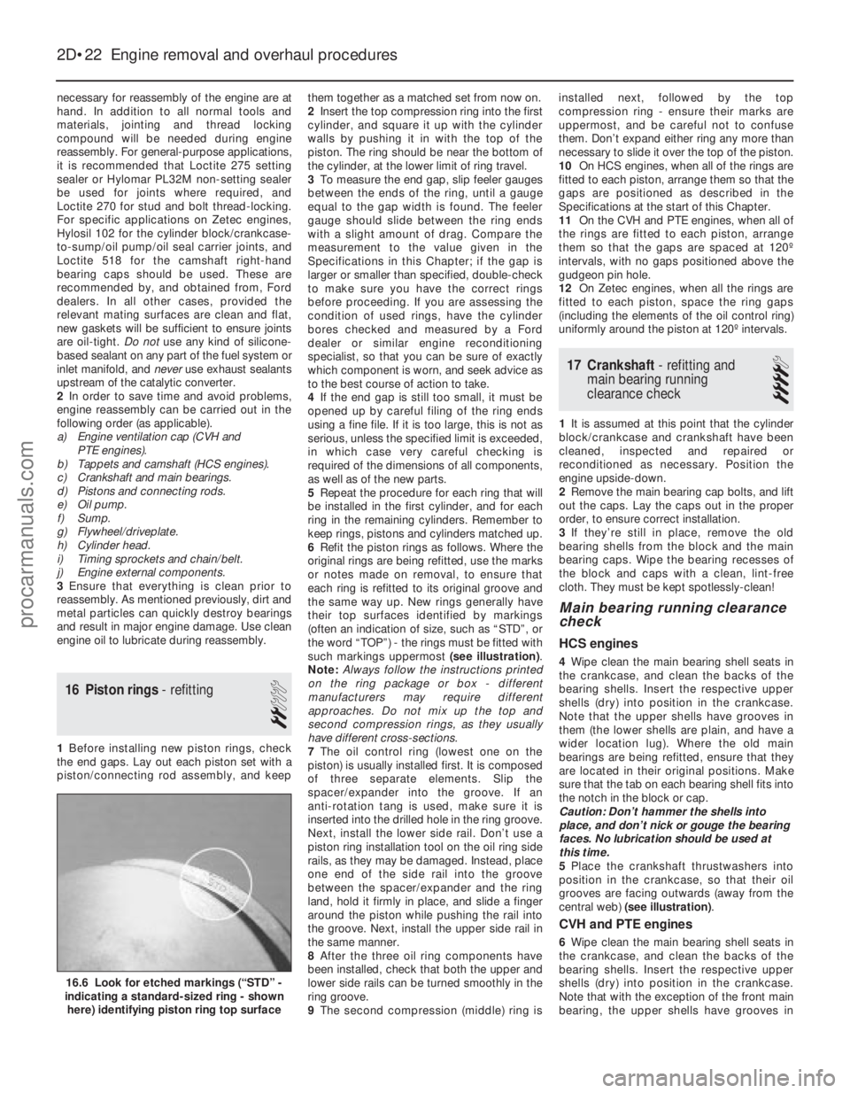
such markings uppermost (see illustration) .
Note: Always follow the instructions printed
on the ring package or box - different
manufacturers may require different
approaches. Do not mix up the top and
second compression rings, as they usually
have different cross-sections.
7 The oil control ring (lowest one on the
piston) is usually installed first. It is composed
of three separate elements. Slip the
spacer/expander into the groove. If an
anti- rotation tang is used, make sure it is
inserted into the drilled hole in the ring groove.
Next, install the lower side rail. Don’t use a
piston ring installation tool on the oil ring side
rails, as they may be damaged. Instead, place
one end of the side rail into the groove
between the spacer/expander and the ring
land, hold it firmly in place, and slide a finger
around the piston while pushing the rail into
the groove. Next, install the upper side rail in
the same manner.
8 After the three oil ring components have
been installed, check that both the upper and
lower side rails can be turned smoothly in the
ring groove.
9 The second compression (middle) ring is installed next, followed by the top
compression ring - ensure their marks are
uppermost, and be careful not to confuse
them. Don’t expand either ring any more than
necessary to slide it over the top of the piston.
10
On HCS engines, when all of the rings are
fitted to each piston, arrange them so that the
gaps are positioned as described in the
Specifications at the start of this Chapter.
11 On the CVH and PTE engines, when all of
the rings are fitted to each piston, arrange
them so that the gaps are spaced at 120º
intervals, with no gaps positioned above the
gudgeon pin hole.
12 On Zetec engines, when all the rings are
fitted to each piston, space the ring gaps
(including the elements of the oil control ring)
uniformly around the piston at 120º intervals.
17 Crankshaft - refitting and
main bearing running
clearance check
4
1 It is assumed at this point that the cylinder
block/crankcase and crankshaft have been
cleaned, inspected and repaired or
reconditioned as necessary. Position the
engine upside-down.
2 Remove the main bearing cap bolts, and lift
out the caps. Lay the caps out in the proper
order, to ensure correct installation.
3 If they’re still in place, remove the old
bearing shells from the block and the main
bearing caps. Wipe the bearing recesses of
the block and caps with a clean, lint-free
cloth. They must be kept spotlessly-clean!
Main bearing running clearance
check
HCS engines
4 Wipe clean the main bearing shell seats in
the crankcase, and clean the backs of the
bearing shells. Insert the respective upper
shells (dry) into position in the crankcase.
Note that the upper shells have grooves in
them (the lower shells are plain, and have a
wider location lug). Where the old main
bearings are being refitted, ensure that they
are located in their original positions. Make
sure that the tab on each bearing shell fits into
the notch in the block or cap.
Caution: Don’t hammer the shells into
place, and don’t nick or gouge the bearing
faces. No lubrication should be used at
this time.
5 Place the crankshaft thrustwashers into
position in the crankcase, so that their oil
grooves are facing outwards (away from the
central web) (see illustration) .
CVH and PTE engines
6Wipe clean the main bearing shell seats in
the crankcase, and clean the backs of the
bearing shells. Insert the respective upper
shells (dry) into position in the crankcase.
Note that with the exception of the front main
bearing, the upper shells have grooves in
2D•22 Engine removal and overhaul procedures
16.6 Look for etched markings (“STD” -
indicating a standard-sized ring - shown
here) identifying piston ring top surface
1595Ford Fiesta Remakeprocarmanuals.com
http://vnx.su
Page 100 of 296
6Unscrew the nut securing the cooling fan
shroud to the radiator, noting the insulating
washer arrangement, then lift the fan shroud
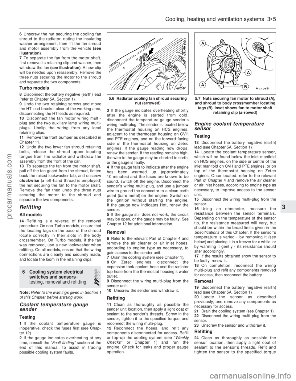
and motor assembly from the vehicle (see
illustration) .
7 To separate the fan from the motor shaft,
first remove its retaining clip and washer, then
withdraw the fan (see illustration) . A new clip
will be needed upon reassembly. Remove the
three nuts securing the motor to the shroud
and separate the two components.
Turbo models
8 Disconnect the battery negative (earth) lead
(refer to Chapter 5A, Section 1).
9 Undo the two retaining screws and move
the HT lead bracket clear of the working area,
disconnecting the HT leads as required.
10 Disconnect the fan motor wiring multi-
plug and the two auxiliary lamp wiring multi-
plugs. Unclip the wiring from any local
retaining clips.
11 Remove the front bumper as described in
Chapter 11.
12 Undo the two lower fan shroud retaining
bolts, release the shroud upper locating
tongue from the radiator and withdraw the
assembly from the front of the car.
13 To separate the fan from the motor shaft,
pull off the fan guard from the shroud, flatten
back the raised lockwasher tab, and unscrew
clockwise (a left-hand thread is employed)
the nut securing the fan to the motor shaft.
Remove the fan then undo the three nuts
securing the motor to the shroud and
separate the two components.
Refitting
All models
14 Refitting is a reversal of the removal
procedure. On non-Turbo models, ensure that
the locating tags on the base of the shroud
locate correctly in their slots in the body
crossmember. On Turbo models, if the fan
was removed, use a new lockwasher when
refitting. On all models, ensure that the wiring
connections are cleanly and securely made,
and locate the loom in the retaining clips.
6 Cooling system electrical switches and sensors -
testing, removal and refitting
2
Note: Refer to the warnings given in Section 1
of this Chapter before starting work.
Coolant temperature gauge
sender
Testing
1 If the coolant temperature gauge is
inoperative, check the fuses first (see Chap-
ter 12).
2 If the gauge indicates overheating at any
time, consult the “Fault finding” section at the
end of this manual, to assist in tracing
possible cooling system faults. 3
If the gauge indicates overheating shortly
after the engine is started from cold,
disconnect the temperature gauge sender’s
wiring multi-plug. The sender is located below
the thermostat housing on HCS engines,
adjacent to the thermostat housing on CVH
and PTE engines, and on the forward-facing
side of the thermostat housing on Zetec
engines. If the gauge reading now drops,
renew the sender. If the reading remains high,
the wire to the gauge may be shorted to earth,
or the gauge is faulty.
4 If the gauge fails to indicate after the engine
has been warmed up (approximately
10 minutes) and the fuses are known to be
sound, switch off the engine. Disconnect the
sender’s wiring multi-plug, and use a jumper
wire to ground the connector to a clean earth
point (bare metal) on the engine. Switch on
the ignition without starting the engine.
If the gauge now indicates Hot, renew the
sender.
5 If the gauge still does not work, the circuit
may be open, or the gauge may be faulty. See
Chapter 12 for additional information.
Removal
6 Refer to the relevant Part of Chapter 4 and
remove the air cleaner or air inlet hoses,
according to engine type as necessary, to
gain access to the sender unit.
7 Drain the cooling system (see Chapter 1).
8 On Zetec engines, disconnect the
expansion tank coolant hose and the radiator
top hose from the thermostat housing’s water
outlet.
9 Disconnect the wiring multi-plug from the
sender unit.
10 Unscrew the sender and withdraw it.
Refitting
11Clean as thoroughly as possible the
sender unit location, then apply a light coat of
sealant to the sender’s threads. Screw in the
sender, tighten it to the specified torque, and
reconnect the wiring multi-plug.
12 Reconnect the hoses, and refit any
components disconnected for access. Refill
or top-up the cooling system (see “Weekly
Checks” or Chapter 1) and run the
engine. Check for leaks and proper gauge
operation.
Engine coolant temperature
sensor
Testing
13 Disconnect the battery negative (earth)
lead (see Chapter 5A, Section 1).
14 Locate the coolant temperature sensor,
which will be found below the inlet manifold
on HCS engines, on the side or centre of the
inlet manifold on CVH and PTE engines, or on
top of the thermostat housing on Zetec
engines. Once located, refer to the relevant
Part of Chapter 4 and remove the air cleaner
or air inlet hoses, according to engine type as
necessary, to improve access to the sensor
unit.
15 Disconnect the wiring multi-plug from the
sensor.
16 Using an ohmmeter, measure the
resistance between the sensor terminals.
Depending on the temperature of the sensor
tip, the resistance measured will vary, but
should be within the broad limits given in the
Specifications of this Chapter. If the sensor’s
temperature is varied - by removing it (see
below) and placing it in a freezer for a while, or
by warming it gently - its resistance should
alter accordingly.
17 If the results obtained show the sensor to
be faulty, renew it.
18 On completion, reconnect the wiring
multi-plug and refit any components removed
for access, then reconnect the battery.
Removal
19 Disconnect the battery negative (earth)
lead (see Chapter 5A, Section 1).
20 Locate the sensor as described
previously, and remove any components as
necessary for access.
21 Drain the cooling system (see Chapter 1).
22 Disconnect the wiring multi-plug from the
sensor.
23 Unscrew the sensor and withdraw it.
Refitting
24Clean as thoroughly as possible the
sensor location, then apply a light coat of
sealant to the sensor’s threads. Refit and
tighten the sensor to the specified torque
Cooling, heating and ventilation systems 3•5
5.7 Nuts securing fan motor to shroud (A),
and shroud to body crossmember locating tags (B). Inset shows fan to motor shaft retaining clip (arrowed)5.6 Radiator cooling fan shroud securing nut (arrowed)
3
1595Ford Fiesta Remakeprocarmanuals.com
http://vnx.su