1989 FORD FIESTA roof rack
[x] Cancel search: roof rackPage 16 of 296
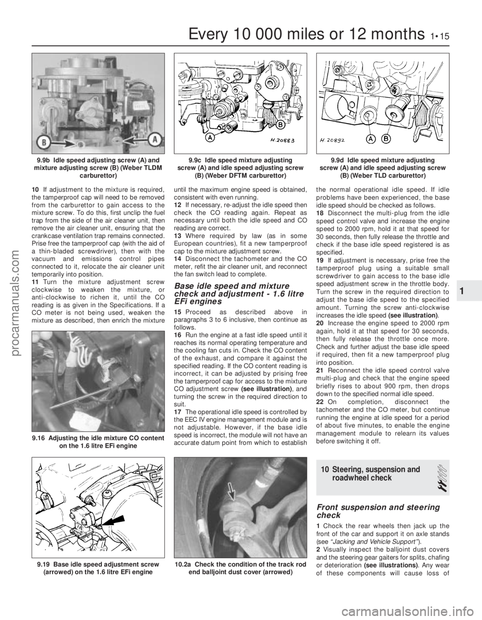
10If adjustment to the mixture is required,
the tamperproof cap will need to be removed
from the carburettor to gain access to the
mixture screw. To do this, first unclip the fuel
trap from the side of the air cleaner unit, then
remove the air cleaner unit, ensuring that the
crankcase ventilation trap remains connected.
Prise free the tamperproof cap (with the aid of
a thin-bladed screwdriver), then with the
vacuum and emissions control pipes
connected to it, relocate the air cleaner unit
temporarily into position.
11 Turn the mixture adjustment screw
clockwise to weaken the mixture, or
anti-clockwise to richen it, until the CO
reading is as given in the Specifications. If a
CO meter is not being used, weaken the
mixture as described, then enrich the mixture until the maximum engine speed is obtained,
consistent with even running.
12
If necessary, re-adjust the idle speed then
check the CO reading again. Repeat as
necessary until both the idle speed and CO
reading are correct.
13 Where required by law (as in some
European countries), fit a new tamperproof
cap to the mixture adjustment screw.
14 Disconnect the tachometer and the CO
meter, refit the air cleaner unit, and reconnect
the fan switch lead to complete.
Base idle speed and mixture
check and adjustment - 1.6 litre
EFi engines
15 Proceed as described above in
paragraphs 3 to 6 inclusive, then continue as
follows.
16 Run the engine at a fast idle speed until it
reaches its normal operating temperature and
the cooling fan cuts in. Check the CO content
of the exhaust, and compare it against the
specified reading. If the CO content reading is
incorrect, it can be adjusted by prising free
the tamperproof cap for access to the mixture
CO adjustment screw (see illustration), and
turning the screw in the required direction to
suit.
17 The operational idle speed is controlled by
the EEC IV engine management module and is
not adjustable. However, if the base idle
speed is incorrect, the module will not have an
accurate datum point from which to establish the normal operational idle speed. If idle
problems have been experienced, the base
idle speed should be checked as follows.
18
Disconnect the multi-plug from the idle
speed control valve and increase the engine
speed to 2000 rpm, hold it at that speed for
30 seconds, then fully release the throttle and
check if the base idle speed registered is as
specified.
19 If adjustment is necessary, prise free the
tamperproof plug using a suitable small
screwdriver to gain access to the base idle
speed adjustment screw in the throttle body.
Turn the screw in the required direction to
adjust the base idle speed to the specified
amount. Turning the screw anti-clockwise
increases the idle speed (see illustration).
20 Increase the engine speed to 2000 rpm
again, hold it at that speed for 30 seconds,
then fully release the throttle once more.
Check and further adjust the base idle speed
if required, then fit a new tamperproof plug
into position.
21 Reconnect the idle speed control valve
multi-plug and check that the engine speed
briefly rises to about 900 rpm, then drops
down to the specified normal idle speed.
22 On completion, disconnect the
tachometer and the CO meter, but continue
running the engine at idle speed for a period
of about five minutes, to enable the engine
management module to relearn its values
before switching it off.
10 Steering, suspension and roadwheel check
2
Front suspension and steering
check
1Chock the rear wheels then jack up the
front of the car and support it on axle stands
(see “Jacking and Vehicle Support” ).
2 Visually inspect the balljoint dust covers
and the steering gear gaiters for splits, chafing
or deterioration (see illustrations) . Any wear
of these components will cause loss of
Every 10 000 miles or 12 months1•15
9.9d Idle speed mixture adjusting
screw (A) and idle speed adjusting screw (B) (Weber TLD carburettor)9.9c Idle speed mixture adjusting
screw (A) and idle speed adjusting screw (B) (Weber DFTM carburettor)9.9b Idle speed adjusting screw (A) and
mixture adjusting screw (B) (Weber TLDM carburettor)
10.2a Check the condition of the track rodend balljoint dust cover (arrowed)9.19 Base idle speed adjustment screw(arrowed) on the 1.6 litre EFi engine
9.16 Adjusting the idle mixture CO content on the 1.6 litre EFi engine
1
1595Ford Fiesta Remakeprocarmanuals.com
http://vnx.su
Page 108 of 296
1 General information andprecautions
General information
The fuel system on all models with
carburettor induction comprises a rear-
mounted fuel tank, a mechanical diaphragm
fuel pump, a carburettor and an air cleaner. The fuel tank is mounted at the rear, under
the floorpan behind the rear seats. The tank
has a “ventilation-to-atmosphere system”
through a combined roll-over/anti-trickle fill
valve assembly, located in the left-hand rear
wheel arch. A filler neck sensing pipe, integral
with the fuel tank filler pipe, will shut off the
petrol pump filler gun when the predetermined
maximum level of fuel is reached in the tank,
so preventing spillage and wastage. A
conventional fuel level sender unit is mounted
in the top face of the fuel tank. One of two fuel pump types will be fitted,
depending on the engine type. On HCS
engines, the fuel pump is operated by a
pivoting rocker arm; one end rests on an
eccentric lobe on the engine camshaft, and
the other end is attached to the fuel pump
diaphragm. The pump fitted to the CVH
engine is operated by a separate pushrod,
one end rests on an eccentric lobe on the
engine camshaft, and the other rests on the
pump actuating rod which operates the
diaphragm. Both types of mechanical pump
incorporate a nylon mesh filter, and are of
sealed type (they cannot be serviced or
overhauled). Four different types of Weber carburettor
are featured in the range, further details being
given in later Sections of this Chapter. The air cleaner incorporates a “waxstat”
controlled air inlet, supplying either hot air
from a shroud mounted around the exhaust
manifold, or cool air from a duct in the front of
the vehicle.
Precautions
Warning: Petrol is extremely
flammable - great care must be
taken when working on any part of the fuel system. Do not smoke or allow
any naked flames or uncovered light bulbs
near the work area. Note that gas powered
domestic appliances with pilot flames,
such as heaters, boilers and tumble
dryers, also present a fire hazard - bear
this in mind if you are working in an area
where such appliances are present.
Always keep a suitable fire extinguisher
close to the work area and familiarise
yourself with its operation before starting
work. Wear eye protection when working
on fuel systems and wash off any fuel spilt
on bare skin immediately with soap and
water. Note that fuel vapour is just as
dangerous as liquid fuel; a vessel that has
just been emptied of liquid fuel will still
contain vapour and can be potentially
explosive. Petrol is a highly dangerous and
volatile liquid, and the precautions
necessary when handling it cannot be
overstressed.
Many of the operations described in this
Chapter involve the disconnection of fuel
lines, which may cause an amount of fuel
spillage. Before commencing work, refer
to the above Warning and the information
in “Safety first” at the beginning of this
manual.
When working with fuel system
components, pay particular attention to
cleanliness - dirt entering the fuel system
may cause blockages which will lead to
poor running.
Certain adjustment points in the fuel system
are protected by tamperproof caps, plugs or
seals. In some territories, it is an offence to
drive a vehicle with broken or missing
tamperproof seals. Before disturbing a
tamperproof seal, first check that no local or
national laws will be broken by doing so, and
fit a new tamperproof seal after adjustment is
complete, where required by law. Do not
break tamperproof seals on any vehicle whilst
it is still under warranty. Carburettors are delicate instruments, and
care must be taken not to disturb any
components unnecessarily. Before attempting
work on a carburettor, ensure that the relevant
spares are available; it should be noted that a complete strip down of a carburettor is
unlikely to cure a fault which is not
immediately obvious, without introducing new
problems. If persistent problems occur, it is
recommended that the services of a Ford
dealer or a carburettor specialist are sought.
Most dealers will be able to provide
carburettor rejetting and servicing facilities.
Where necessary, it may be possible to
purchase a reconditioned carburettor.
2 Air cleaner
-
removal and refitting
1
Note: Air cleaner element renewal and air
cleaner temperature control system checks
are described in Chapter 1.
Removal
1 Disconnect the battery negative (earth) lead
(refer to Chapter 5A, Section 1).
2 On CVH engine models, pull free and
release the accelerator cable from the locating
clip on the side of the air cleaner.
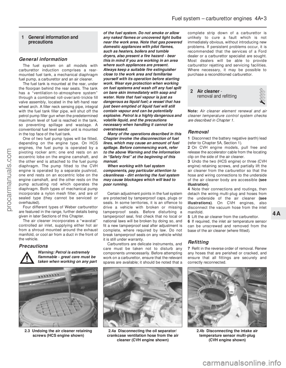
3 Undo the two (HCS engine) or three (CVH
engine) retaining screws, and partially lift the
air cleaner from the carburettor so that the
hose and wiring connections to the underside
of the air cleaner body are accessible (see
illustration) .
4 Note their connections and routings, then
detach the wiring multi-plug and hoses from
the underside of the air cleaner (see
illustrations) . On CVH engines, also
disconnect the vacuum hose from the inlet
manifold.
5 Lift the air cleaner from the carburettor.
6 If required, the inlet air temperature sensor
can be unscrewed and removed from the
base of the air cleaner (where fitted).
Refitting
7 Refit in the reverse order of removal. Renew
any hoses that are perished or cracked, and
ensure that all fittings are securely and
correctly reconnected.
Fuel system – carburettor engines 4A•3
2.4b Disconnecting the intake air temperature sensor multi-plug
(CVH engine shown)2.4a Disconnecting the oil separator/
crankcase ventilation hose from the air
cleaner (CVH engine shown)2.3 Undoing the air cleaner retainingscrews (HCS engine shown)
4A
1595Ford Fiesta Remakeprocarmanuals.com
http://vnx.su
Page 116 of 296
7Detach the vacuum hose between the
throttle kicker and the inlet manifold at source
(but not the vacuum supply to the ignition
module). Connect a new length of vacuum
hose directly between the manifold and the
kicker unit.
8 Restart the engine and check the engine
speed. The throttle kicker should increase the
engine speed above its normal idle. Check the
speed registered against the specified throttle
kicker operating speed.
9 If required, the throttle kicker speed can be
adjusted by prising free the tamperproof plug
and the adjustment screw turned as
necessary (see illustration 21.3) .
10 When the adjustment is complete, stop
the engine, fit a new tamperproof plug,
disconnect the temporary vacuum hose
(between the manifold and the kicker unit) and
reconnect the original hose (between the
carburettor and the kicker unit).
11 Remove the bridging wire, and reconnect
the cooling fan thermostatic switch multi-
plug. Refit and secure the air cleaner, and
disconnect the tachometer and CO meter to
complete.
22 Throttle kicker control solenoid
(Weber TLDM carburettor) -
removal and refitting
2
Removal
1 Disconnect the battery negative (earth) lead
(refer to Chapter 5A, Section 1).
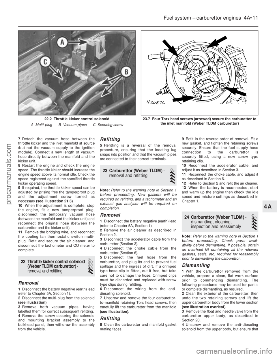
2 Disconnect the multi-plug from the solenoid
(see illustration) .
3 Remove both vacuum pipes, having
labelled them for correct subsequent refitting.
4 Remove the screw securing the solenoid
and mounting bracket assembly to the
bulkhead panel, then withdraw the assembly
from the vehicle.
Refitting
5 Refitting is a reversal of the removal
procedure, ensuring that the locating lug
snaps into position and that the vacuum pipes
are connected to their correct terminals.
23 Carburettor (Weber TLDM) -
removal and refitting
4
Note: Refer to the warning note in Section 1
before proceeding. New gaskets will be
required on refitting, and a tachometer and an
exhaust gas analyser will be required on
completion.
Removal
1 Disconnect the battery negative (earth) lead
(refer to Chapter 5A, Section 1).
2 Remove the air cleaner as described in
Section 2.
3 Disconnect the accelerator cable from the
carburettor (Section 3).
4 Disconnect the choke cable from the
carburettor (Section 6).
5 Disconnect the fuel hose from the
carburettor, and plug its end to prevent fuel
spillage and the ingress of dirt. If a crimped
type hose clip is fitted, cut it free, but take
care not to damage the hose. Crimped clips
must be discarded and replaced with screw
type clips during refitting.
6 Disconnect the wiring from the anti-
dieseling solenoid.
7 Unscrew and remove the four carburettor-
to-manifold retaining Torx head screws, then
carefully lift the carburettor from the manifold
(see illustration) .
Refitting
8Clean the carburettor and manifold gasket
mating faces. 9
Refit in the reverse order of removal. Fit a
new gasket, and tighten the retaining screws
securely. Ensure that the fuel supply hose
connection to the carburettor is
securely fitted, using a new screw type
retaining clip.
10 Reconnect the accelerator cable, and
adjust it as described in Section 3.
11 Reconnect the choke cable, and adjust it
as described in Section 6.
12 Refer to Section 2 and refit the air cleaner.
13 When the battery is reconnected, start
and warm up the engine then check the idle
speed and mixture settings as described in
Chapter 1.
24 Carburettor (Weber TLDM) -
dismantling, cleaning,
inspection and reassembly
4
Note: Refer to the warning note in Section 1
before proceeding. Check parts avail-
ability before dismantling. If possible, obtain
an overhaul kit containing all the relevant
gaskets, seals, etc, required for reassembly
prior to dismantling the carburettor.
Dismantling
1 With the carburettor removed from the
vehicle, prepare a clean, flat work surface
prior to commencing dismantling. The
following procedures may be used for partial
or complete dismantling, as required.
2 Clean the exterior of the carburettor, then
undo the two retaining screws and lift the
upper carburettor body from the lower section
(see illustration overleaf) .
3 Remove the float and needle valve from the
carburettor upper body, as described in
Section 20.
4 Unscrew and remove the anti-dieseling
solenoid from the upper body, but ensure that
Fuel system – carburettor engines 4A•11
23.7 Four Torx head screws (arrowed) secure the carburettor to the inlet manifold (Weber TLDM carburettor)22.2 Throttle kicker control solenoid
A Multi-plug B Vacuum pipes C Securing screw
4A
1595Ford Fiesta Remakeprocarmanuals.com
http://vnx.su
Page 118 of 296
14Prise free and remove the tamperproof
seal, then unscrew and remove the idle
mixture adjustment screw.
15 Undo the retaining screws, and remove
the throttle housing from the carburettor main
body.
Cleaning and inspection
16 Wash the carburettor components,
drillings and passages with clean petrol, then
blow them dry using a low-pressure air line. A
high-pressure air line must not be applied to
the accelerator pump discharge assembly or
the pump supply valve, as they each contain a
rubber Vernay valve, and these can easily be
damaged under high pressure. Never use a
piece of wire for cleaning purposes.
17 Examine all of the carburettor
components for signs of damage or wear,
paying particular attention to the diaphragms,
throttle spindle and plates, needle valve and
mixture screw; the power valve jet is adjacent
to the primary main jet. Renew all
diaphragms, sealing washers and gaskets as
a matter of course.
Reassembly
18 Refit the throttle housing to the
carburettor main body (fitting a new gasket),
and secure with its retaining screws.
19 Refit the idle mixture adjustment screw.
Make an initial adjustment by screwing it fully
in (but do not overtighten or screw it onto its
seat), then unscrew it two full turns.
20 Where fitted, reassemble the throttle
kicker, ensuring that its diaphragm lies flat,
and that the relative position of the operating
link to the kicker cover is correct.
21 Fit the power valve, ensuring that its
diaphragm lies flat and the vacuum
gallery aligns with the diaphragm and
housing.
22 Refit the accelerator pump. Take care not
damage the valve as it is inserted, and check
that the O-ring seal is correctly located on the
end of the valve. Check that the valve is not
trapped by the spring.
23 Refit the accelerator pump discharge jet.
Take care not to damage the valve and/or the
O-ring seal, and ensure that they are correctly
located.
24 Commence reassembly of the upper body
by inserting the emulsion tubes and the air
correction jets into their respective ports (as
noted during removal).
25 Screw the anti-dieseling solenoid into
position. Ensure that the aluminium washer is
fitted, and take care not to overtighten the
valve.
26 Refit the needle valve and the float, and
adjust the float setting as described in Sec-
tion 20.
27 Refit the choke control mechanism, and
secure with its three retaining screws.
28 Locate a new gasket onto the mating
face, then refit the carburettor upper body to
the main body. As they are reassembled, take
care not to snag the float on the carburettor main body. Fit and tighten the retaining
screws to secure.
29
On completion, refit the carburettor as
described in Section 23. Where applicable,
check and adjust the throttle kicker setting
(Section 21) after adjusting the idle speed and
mixture settings.
25 Carburettor (Weber DFTM) -
description
The carburettor operates in essentially the
same manner as TLDM instrument described
in Section 18, but the following features
should be noted. A throttle kicker is fitted to both manual
transmission, and CTX automatic trans-
mission models, the operation of the unit is
described in Section 18. The secondary venturi (barrel) is vacuum-
operated on manual transmission models. On
CTX automatic transmission equipped models
it is operated sequentially. A bleed back solenoid (if fitted) is used to
control the amount of fuel being delivered to
the venturi by the action of the accelerator
pump. Idle speed and mixture adjustment
procedures are described in Chapter 1, but it
is important to note that accurate adjustments
can only be made using the necessary
equipment.
26 Carburettor (Weber DFTM) -
fast-idle speed adjustment
4
Refer to the procedure contained in Sec-
tion 19, but note the following points:
a) When removing the air cleaner, do not disconnect the vacuum supply or
crankcase ventilation hoses; the air
cleaner should be positioned clear of the
carburettor assembly.
b) The fast-idle adjusting screw is located
on the side of the linkage (see
illustration) .
27 Throttle kicker unit (Weber
DFTM carburettor) - removal,
refitting and adjustment
4
Refer to the procedure contained in Sec-
tion 21.
28 Carburettor (Weber DFTM) -
removal and refitting
4
Note: Refer to the warning note in Section 1
before proceeding. New gaskets will be
required on refitting, and a tachometer and an
exhaust gas analyser will be required on
completion.
Removal
1 Disconnect the battery negative (earth) lead
(refer to Chapter 5A, Section 1).
2 Remove the air cleaner as described in
Section 2.
3 Disconnect the choke cable from the
carburettor (Section 6).
4 Carefully prise out the accelerator link
retaining clip, remove both securing bolts,
then detach the cable and bracket assembly.
Position the cable and bracket assembly clear
of the carburettor.
5 Disconnect the fuel feed hose at the
carburettor, and plug its end to avoid spillage
and prevent dirt ingress. If a crimped type
hose clip is fitted, cut this free taking care not
to damage the hose.
6 Disconnect all relevant vacuum pipes from
the carburettor, having labelled them for
subsequent refitting.
7 Disconnect the electrical lead from the anti-
dieseling (fuel cut-off) solenoid, and the bleed
back solenoid (if fitted).
8 Remove the four nuts securing the
carburettor to the inlet manifold, then
withdraw it from the vehicle.
Refitting
9 Clean the carburettor and manifold gasket
mating faces.
10 Refit in the reverse order of removal. Fit a
new gasket, and tighten the retaining screws
securely. Ensure that the fuel supply
hose connection to the carburettor is
securely fitted, using a new screw type
retaining clip.
11 Reconnect the choke cable, and adjust it
as described in Section 6.
12 Refer to Section 2 and refit the air
cleaner.
13 When the battery is reconnected, start
and warm up the engine then check the idle
speed and mixture settings as described in
Chapter 1.
Fuel system – carburettor engines 4A•13
26.1 Manual choke fast-idle adjustment. Inset shows fast-idle adjusting screw (Weber DFTM carburettor)
4A
1595Ford Fiesta Remakeprocarmanuals.com
http://vnx.su
Page 120 of 296
16Prise out the tamperproof seal covering
the fuel mixture screw, then undo and remove
the mixture screw.
Cleaning and inspection
17 Wash the carburettor components,
drillings and passages with clean petrol, then
blow them dry using a low-pressure air line. A
high-pressure air line must not be applied to
the accelerator pump discharge assembly or
the pump supply valve, as they each contain a
rubber Vernay valve, and these can easily be
damaged under high pressure. Never use a
piece of wire for cleaning purposes.
18 Examine all of the carburettor
components for signs of damage or wear,
paying particular attention to the diaphragms,
throttle spindle and plates, needle valve and
mixture screw; the power valve jet is adjacent
to the primary main jet. Renew all
diaphragms, sealing washers and gaskets as
a matter of course.
Reassembly
19 Refit the fuel mixture screw by fully
winding the screw in, then unwinding three
turns to give an approximate setting.
20 Refit the power valve assembly ensuring
that the diaphragm lies flat, and that the
vacuum gallery lines up correctly with the
diaphragm and housing.
21 Reassemble the secondary barrel
diaphragm into its housing, ensuring that
the diaphragm lies flat and that the vacuum
gallery lines up with the diaphragm and
housing. Also, to assist with installation, do
not reconnect its operating rod until the cover
has been secured.
22 Refit the throttle kicker mounting bracket.
23 Refit the anti-dieseling (fuel cut-off)
solenoid, using a new sealing washer.
24 Refit the accelerator pump assembly,
ensuring that the diaphragm lies flat and is not
kinked.
25 Reassemble the throttle kicker, ensuring
that the diaphragm lies flat and that the relative position of the diaphragm operating
link to the throttle kicker cover is correct. Fully
attach the throttle kicker assembly.
26
Refit the main and idle jets, making
reference to the notes taken during
dismantling to ensure correct fitted locations.
27 Reassemble the carburettor upper body
as described in the following paragraphs.
28 Refit the needle valve housing (using a
new washer if applicable).
29 Refit the needle valve and float assembly,
having ensured that the float tag locates
below the spring clip on the needle valve.
Insert the float retaining pin to secure.
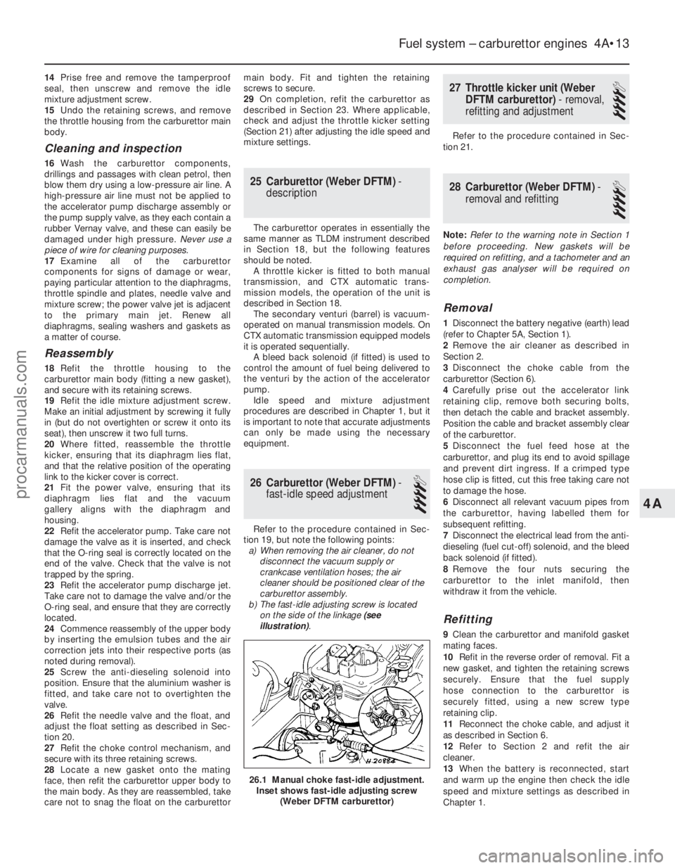
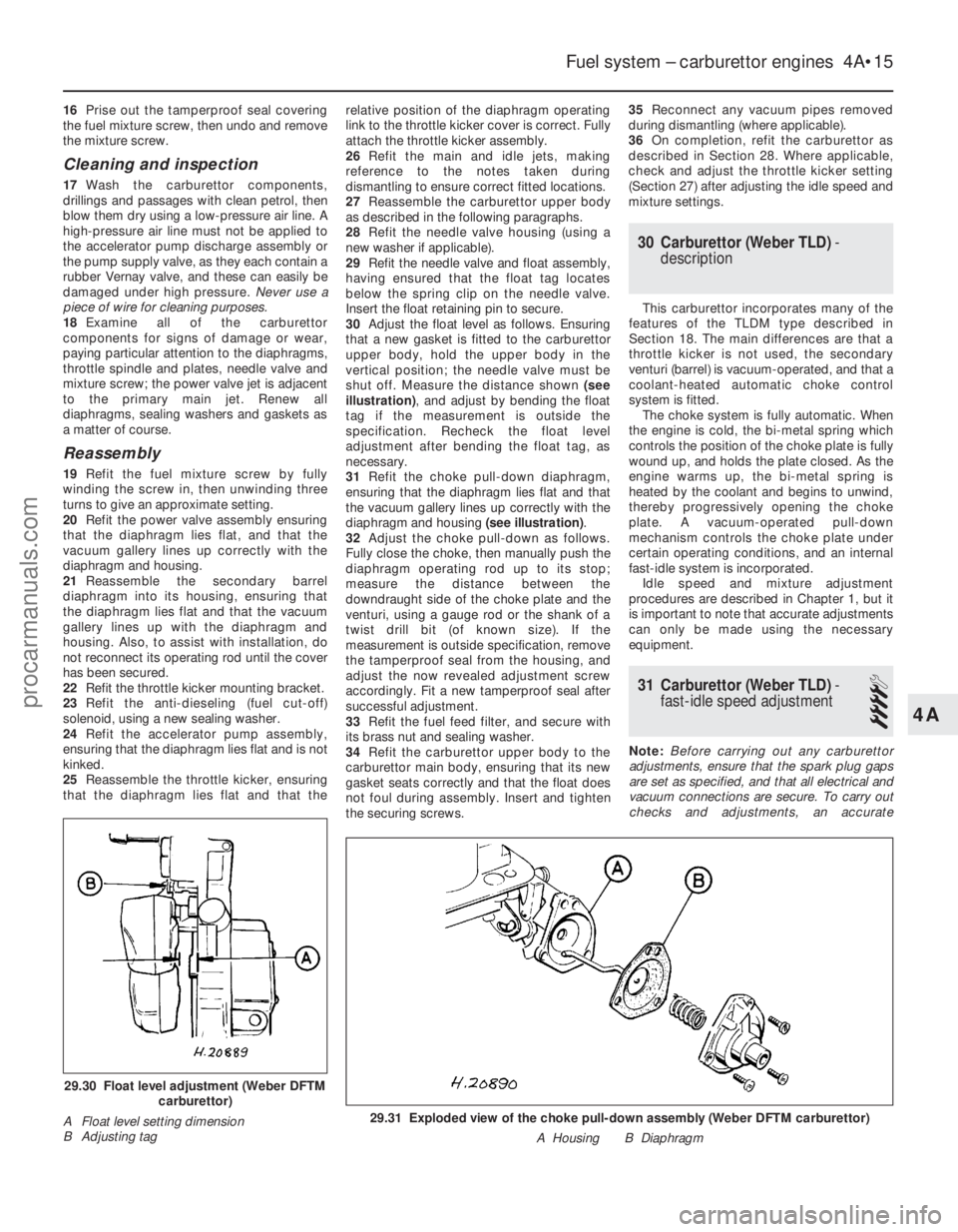
30 Adjust the float level as follows. Ensuring
that a new gasket is fitted to the carburettor
upper body, hold the upper body in the
vertical position; the needle valve must be
shut off. Measure the distance shown (see
illustration) , and adjust by bending the float
tag if the measurement is outside the
specification. Recheck the float level
adjustment after bending the float tag, as
necessary.
31 Refit the choke pull-down diaphragm,
ensuring that the diaphragm lies flat and that
the vacuum gallery lines up correctly with the
diaphragm and housing (see illustration).
32 Adjust the choke pull-down as follows.
Fully close the choke, then manually push the
diaphragm operating rod up to its stop;
measure the distance between the
downdraught side of the choke plate and the
venturi, using a gauge rod or the shank of a
twist drill bit (of known size). If the
measurement is outside specification, remove
the tamperproof seal from the housing, and
adjust the now revealed adjustment screw
accordingly. Fit a new tamperproof seal after
successful adjustment.
33 Refit the fuel feed filter, and secure with
its brass nut and sealing washer.
34 Refit the carburettor upper body to the
carburettor main body, ensuring that its new
gasket seats correctly and that the float does
not foul during assembly. Insert and tighten
the securing screws. 35
Reconnect any vacuum pipes removed
during dismantling (where applicable).
36 On completion, refit the carburettor as
described in Section 28. Where applicable,
check and adjust the throttle kicker setting
(Section 27) after adjusting the idle speed and
mixture settings.
30 Carburettor (Weber TLD) -
description
This carburettor incorporates many of the
features of the TLDM type described in
Section 18. The main differences are that a
throttle kicker is not used, the secondary
venturi (barrel) is vacuum-operated, and that a
coolant-heated automatic choke control
system is fitted. The choke system is fully automatic. When
the engine is cold, the bi-metal spring which
controls the position of the choke plate is fully
wound up, and holds the plate closed. As the
engine warms up, the bi-metal spring is
heated by the coolant and begins to unwind,
thereby progressively opening the choke
plate. A vacuum-operated pull-down
mechanism controls the choke plate under
certain operating conditions, and an internal
fast-idle system is incorporated. Idle speed and mixture adjustment
procedures are described in Chapter 1, but it
is important to note that accurate adjustments
can only be made using the necessary
equipment.
31 Carburettor (Weber TLD) -
fast-idle speed adjustment
4
Note: Before carrying out any carburettor
adjustments, ensure that the spark plug gaps
are set as specified, and that all electrical and
vacuum connections are secure. To carry out
checks and adjustments, an accurate
Fuel system – carburettor engines 4A•15
29.31 Exploded view of the choke pull-down assembly (Weber DFTM carbur\
ettor)
A Housing B Diaphragm
29.30 Float level adjustment (Weber DFTMcarburettor)
A Float level setting dimension
B Adjusting tag
4A
1595Ford Fiesta Remakeprocarmanuals.com
http://vnx.su
Page 216 of 296
4Pull the latch end of the cable into the
engine compartment, noting cable routing and
clips fitted. Remove the cable from its clips.
5 Detach the cable from its release lever on
the steering column, by aligning the cable
core with the slot on the release lever and
withdrawing the end fixing. Detach the cable
from its outer core abutment on the steering
column lock housing.
6 Unclip the cable from its pedal box
location, then detach the bulkhead grommet
and pass the cable through into the engine
compartment. Withdraw the cable from the
vehicle.
7 The release lever on the steering column
may be removed, if required, by unhooking
the spring from its retaining arms, then
disengaging its retaining arms from the
steering column lock housing.
Refitting
8 Refit the release lever, if removed, by
reversing the method of removal.
9 To install the release cable, first pass the
latch end of the cable down the right-hand
side of the steering column, through its
bulkhead location, and out into the engine
compartment.
10 Fit the cable to its clip on the pedal box
assembly, then reconnect the cable to the
release lever and the steering column lock
housing abutment by reversing the method of
removal.
11 Where applicable, refit the choke warning
light switch/pull control assembly, to the lower steering column shroud, by reversing the
method of removal. Refit the shroud.
12
Seat the release cable grommet into the
bulkhead.
13 Route and secure the release cable in the
engine compartment.
14 Reconnect the release cable to the latch,
then refit the latch to the body, setting the
latch at its maximum height position, and
tightening only the bottom retaining screw.
15 Adjust the latch for flush bonnet closure in
accordance with Section 8.
8 Bonnet latch - adjustment
1
1To adjust the bonnet latch, remove the two
upper latch retaining screws, then with the
latch raised to its maximum height position
and secured with the lower retaining screw,
close the bonnet.
2 Slacken the lower latch retaining screw,
through the gap between the leading edge of
the bonnet and the radiator grille slot, then
set the bonnet so it sits flush with its
surrounding panels - it may be necessary to
adjust the height of the bump stops (see
Section 6) if they have been moved in any
way, or if fitting a new bonnet.
3 With the desired bonnet closure obtained,
fully tighten the lower latch retaining screw,
then open the bonnet and refit the two upper
latch retaining screws, tightening to the
specified torque.
9 Body adhesive emblems -
renewal
1
1 Using a length of strong thin diameter cord
(fishing line is ideal), break the adhesive bond
between the emblem and the panel.
2 Thoroughly clean all traces of the old
adhesive from the emblem location, using
methylated spirit, taking all normal safety
precautions. Allow the emblem location to
dry.
3 Gently heat the new emblem until it is warm
to the touch. 4
Peel the protective backing paper from the
emblem then, taking care not to touch the
adhesive, position the emblem on the panel.
Maintain hand pressure evenly for at least
thirty seconds to ensure a good bond.
10 Body trim mouldings -
removal and refitting
1
Roof drip rail moulding (all
models except Courier)
Removal
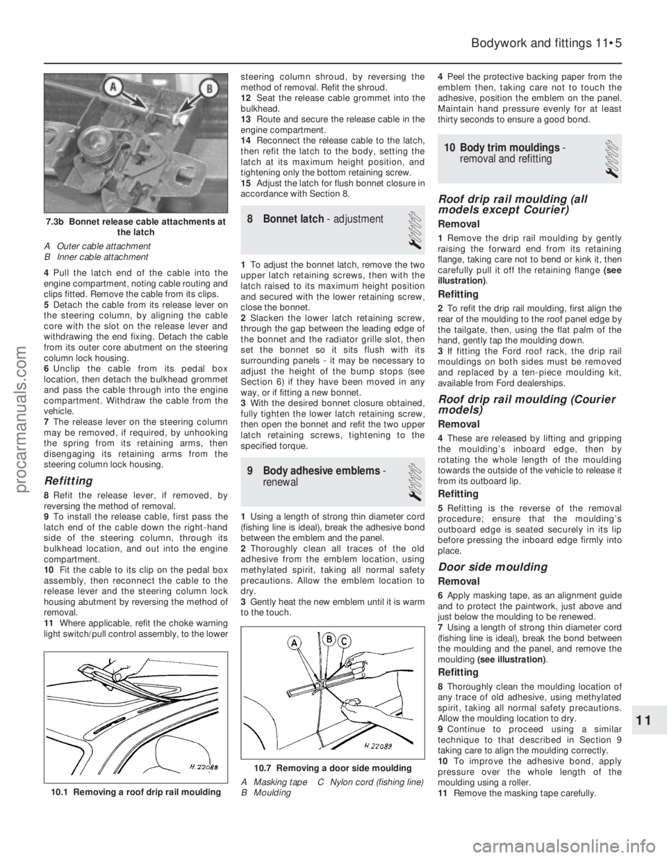
1 Remove the drip rail moulding by gently
raising the forward end from its retaining
flange, taking care not to bend or kink it, then
carefully pull it off the retaining flange (see
illustration) .
Refitting
2To refit the drip rail moulding, first align the
rear of the moulding to the roof panel edge by
the tailgate, then, using the flat palm of the
hand, gently tap the moulding down.
3 If fitting the Ford roof rack, the drip rail
mouldings on both sides must be removed
and replaced by a ten-piece moulding kit,
available from Ford dealerships.
Roof drip rail moulding (Courier
models)
Removal
4 These are released by lifting and gripping
the moulding’s inboard edge, then by
rotating the whole length of the moulding
towards the outside of the vehicle to release it
from its outboard lip.
Refitting
5 Refitting is the reverse of the removal
procedure; ensure that the moulding’s
outboard edge is seated securely in its lip
before pressing the inboard edge firmly into
place.
Door side moulding
Removal
6 Apply masking tape, as an alignment guide
and to protect the paintwork, just above and
just below the moulding to be renewed.
7 Using a length of strong thin diameter cord
(fishing line is ideal), break the bond between
the moulding and the panel, and remove the
moulding (see illustration) .
Refitting
8Thoroughly clean the moulding location of
any trace of old adhesive, using methylated
spirit, taking all normal safety precautions.
Allow the moulding location to dry.
9 Continue to proceed using a similar
technique to that described in Section 9
taking care to align the moulding correctly.
10 To improve the adhesive bond, apply
pressure over the whole length of the
moulding using a roller.
11 Remove the masking tape carefully.
Bodywork and fittings 11•5
7.3b Bonnet release cable attachments at
the latch
A Outer cable attachment
B Inner cable attachment
10.7 Removing a door side moulding
A Masking tape C Nylon cord (fishing line)
B Moulding
10.1 Removing a roof drip rail moulding
11
1595Ford Fiesta Remakeprocarmanuals.com
http://vnx.su
Page 248 of 296
Windscreen washer jets and hoses
10Disconnect the battery negative (earth)
lead (refer to Chapter 5A, Section 1).
11 With the bonnet raised and supported on
its stay, release the fasteners securing its
insulation panel (where fitted). Remove the
insulation panel.
12 Carefully press in the retaining lugs on the
washer jets using a flat-bladed screwdriver,
then raise the washer jets from the exterior
surface of the bonnet and separate them from
their hoses
13 The windscreen washer jet hose may have
been fitted with a one-way (non-return) valve.
If this is the case, the main hose run sections
can be removed from either side of the valve
as required.
14 Chock the rear wheels then jack up the
front of the car and support it on axle stands
(see “Jacking and vehicle support” ).
15 Disconnect the windscreen washer hose
(marked with adhesive tape) from the washer
pump (see illustration 19.2) . Withdraw the
hose from the reservoir guide, and into the
engine compartment.
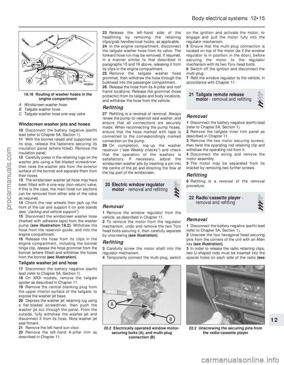
16 Release the hose from its clips in the
engine compartment, including the bonnet
hinge clip, release the hose grommet from the
bonnet (where fitted) and withdraw the hoses
from the bonnet (see illustration) .
Tailgate washer jet and hose
17Disconnect the battery negative (earth)
lead (refer to Chapter 5A, Section 1).
18 On XR2i models, remove the tailgate
spoiler as described in Chapter 11.
19 Remove the central blanking plug from
the upper interior surface of the tailgate, to
expose the washer jet base.
20 Depress the washer jet retaining lug using
a flat-bladed screwdriver, then push the
washer jet out through the panel. From the
outside, fully withdraw the washer jet and
disconnect it from its hose. Note washer jet
seal fitment.
21 Remove the left-hand sun visor.
22 Remove the left-hand A-pillar trim as
described in Chapter 11. 23
Release the left-hand side of the
headlining by removing the retaining
clips/grab handles/coat hooks, as applicable.
24 In the engine compartment, disconnect
the tailgate washer hose from its valve. The
forward hose run may be removed, if required,
in a manner similar to that described in
paragraphs 15 and 16 above, releasing it from
its clips in the engine compartment.
25 Remove the tailgate washer hose
grommet, then withdraw the hose through the
bulkhead into the passenger compartment.
26 Release the hose from its A-pillar and roof
frame locations. Release the grommet (hose
protector) from its tailgate and body locations,
and withdraw the hose from the vehicle.
Refitting
27 Refitting is a reversal of removal. Always
renew the pump-to-reservoir seal washer, and
ensure that all connections are securely
made. When reconnecting the pump hoses,
ensure that the hose marked with tape is
connected to the correspondingly marked
connection on the pump.
28 On completion, top-up the washer
reservoir ( “see Weekly checks” ) and check
that the operation of the washers is
satisfactory. If necessary, adjust the
windscreen washer jets by inserting a pin into
the centre of the jet and directing the flow at
the top part of the windscreen.
20 Electric window regulator motor - removal and refitting
3
Removal
1Remove the window regulator from the
vehicle, as described in Chapter 11.
2 To remove the motor from the regulator
mechanism, undo and remove the two Torx
head bolts securing it, then carefully separate
by unscrewing (see illustration) .
Refitting
3Carefully screw the motor shaft into the
regulator mechanism.
4 Temporarily connect the multi-plug, switch on the ignition and activate the motor, to
engage and pull the motor fully into the
regulator mechanism.
5
Ensure that the multi-plug connection is
located on top of the motor (as if the window
regulator is in position in the door), before
securing the motor to the regulator
mechanism with its two Torx-head bolts.
6 Switch off the ignition and disconnect the
multi-plug.
7 Refit the window regulator to the vehicle, in
accordance with Chapter 11.
21 Tailgate remote release motor - removal and refitting
2
Removal
1Disconnect the battery negative (earth) lead
(refer to Chapter 5A, Section 1).
2 Remove the tailgate inner trim panel as
described in Chapter 11.
3 Remove the two motor securing screws,
then twist the operating rod retaining clip and
withdraw the operating rod from it.
4 Disconnect the wiring and remove the
motor assembly.
5 The motor may be separated from its
bracket by removing two further screws.
Refitting
6 Refitting is a reversal of the removal
procedure.
22 Radio/cassette player -
removal and refitting
3
Removal
1 Disconnect the battery negative (earth) lead
(refer to Chapter 5A, Section 1).
2 Unscrew the four hexagonal head securing
pins from the corners of the unit with an Allen
key (see illustration) .
3 In order to release the radio retaining clips,
two U-shaped rods must be inserted into the
special holes on each side of the radio (see
Body electrical systems 12•15
19.16 Routing of washer hoses in the
engine compartment
A Windscreen washer hose
B Tailgate washer hose
C Tailgate washer hose one-way valve
22.2 Unscrewing the securing pins from the radio/cassette player20.2 Electrically operated window motor-securing bolts (A), and multi-plug
connection (B)
12
1595Ford Fiesta Remakeprocarmanuals.com
http://vnx.su
Page 268 of 296
1595 Ford Fiesta Remake
REF•2Conversion factors
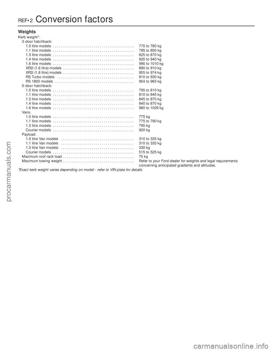
Weights
Kerb weight*:3-door hatchback:1.0 litre models . . . . . . . . . . . . . . . . . . . . . . . . . . . . . . . . . . . .\
. . . . 770 to 780 kg
1.1 litre models . . . . . . . . . . . . . . . . . . . . . . . . . . . . . . . . . . . .\
. . . . 785 to 850 kg
1.3 litre models . . . . . . . . . . . . . . . . . . . . . . . . . . . . . . . . . . . .\
. . . . 825 to 870 kg
1.4 litre models . . . . . . . . . . . . . . . . . . . . . . . . . . . . . . . . . . . .\
. . . . 920 to 940 kg
1.6 litre models . . . . . . . . . . . . . . . . . . . . . . . . . . . . . . . . . . . .\
. . . . 990 to 1010 kg
XR2i (1.6 litre) models . . . . . . . . . . . . . . . . . . . . . . . . . . . . . . . . . . . 890 to 910 kg
XR2i (1.8 litre) models . . . . . . . . . . . . . . . . . . . . . . . . . . . . . . . . . . . 955 to 974 kg
RS Turbo models . . . . . . . . . . . . . . . . . . . . . . . . . . . . . . . . . . . .\
. . 910 to 930 kg
RS 1800 models . . . . . . . . . . . . . . . . . . . . . . . . . . . . . . . . . . . .\
. . . 954 to 965 kg
5-door hatchback: 1.0 litre models . . . . . . . . . . . . . . . . . . . . . . . . . . . . . . . . . . . .\
. . . . 795 to 810 kg
1.1 litre models . . . . . . . . . . . . . . . . . . . . . . . . . . . . . . . . . . . .\
. . . . 810 to 845 kg
1.3 litre models . . . . . . . . . . . . . . . . . . . . . . . . . . . . . . . . . . . .\
. . . . 845 to 870 kg
1.4 litre models . . . . . . . . . . . . . . . . . . . . . . . . . . . . . . . . . . . .\
. . . . 840 to 870 kg
1.6 litre models . . . . . . . . . . . . . . . . . . . . . . . . . . . . . . . . . . . .\
. . . . 980 to 1029 kg
Vans: 1.0 litre models . . . . . . . . . . . . . . . . . . . . . . . . . . . . . . . . . . . .\
. . . . 775 kg
1.1 litre models . . . . . . . . . . . . . . . . . . . . . . . . . . . . . . . . . . . .\
. . . . 775 to 790 kg
1.3 litre models . . . . . . . . . . . . . . . . . . . . . . . . . . . . . . . . . . . .\
. . . . 795 kg
Courier models . . . . . . . . . . . . . . . . . . . . . . . . . . . . . . . . . . . .\
. . . . 920 kg
Payload: 1.0 litre Van models . . . . . . . . . . . . . . . . . . . . . . . . . . . . . . . . . . . .\
310 to 335 kg
1.1 litre Van models . . . . . . . . . . . . . . . . . . . . . . . . . . . . . . . . . . . .\
310 to 335 kg1.3 litre Van models . . . . . . . . . . . . . . . . . . . . . . . . . . . . . . . . . . . .\
330 kgCourier models . . . . . . . . . . . . . . . . . . . . . . . . . . . . . . . . . . . .\
. . . . 515 to 525 kg
Maximum roof rack load . . . . . . . . . . . . . . . . . . . . . . . . . . . . . . . . . . . 75 kg
Maximum towing weight . . . . . . . . . . . . . . . . . . . . . . . . . . . . . . . . . . . Refer to your Ford dealer for weights and legal requirements concerning anticipated gradients and altitudes.
*Exact kerb weight varies depending on model - refer to VIN plate for de\
tails
procarmanuals.com
http://vnx.su