1989 FORD FIESTA ground clearance
[x] Cancel search: ground clearancePage 10 of 296
3 Engine oil and filter renewal
1
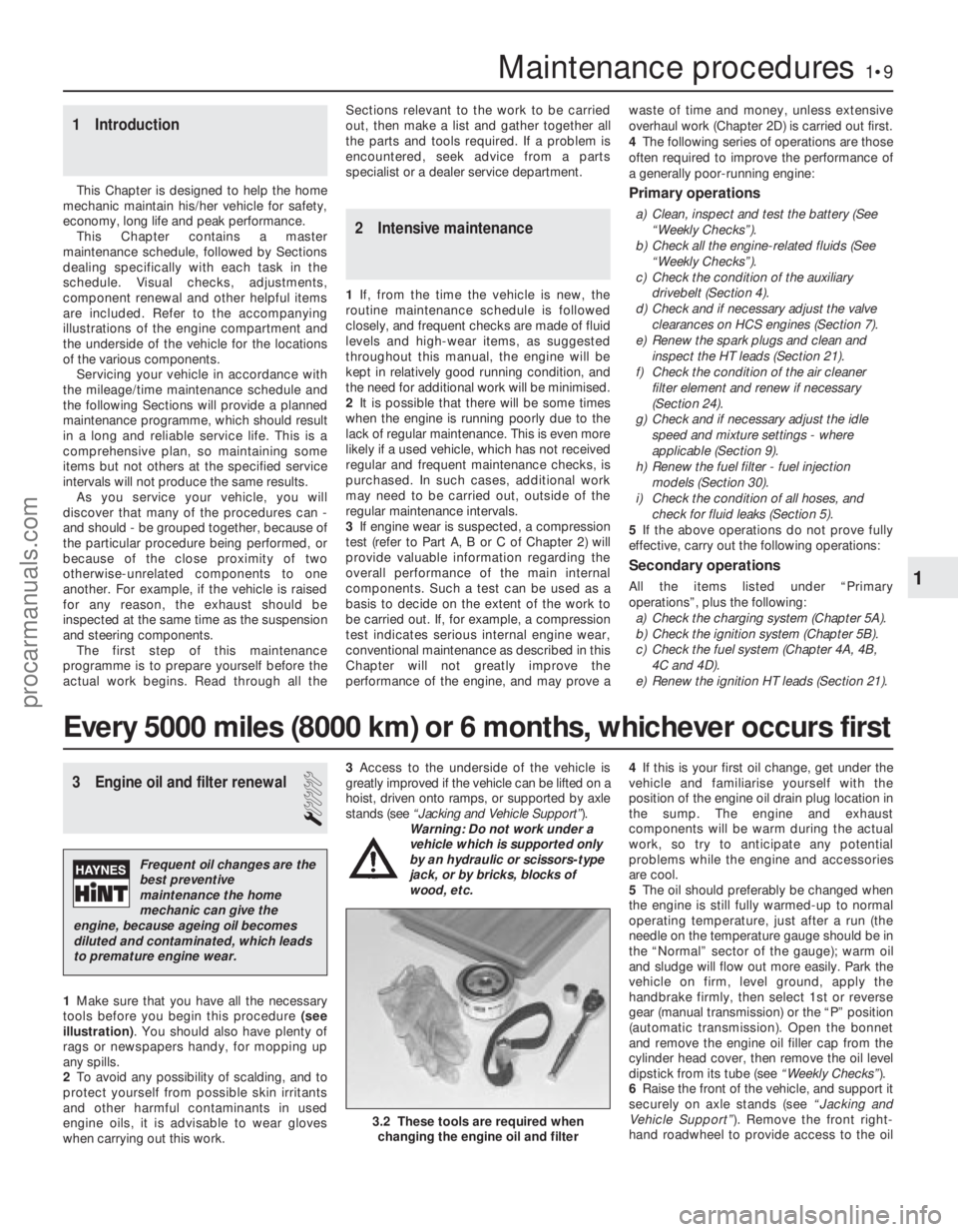
1Make sure that you have all the necessary
tools before you begin this procedure (see
illustration) . You should also have plenty of
rags or newspapers handy, for mopping up
any spills.
2 To avoid any possibility of scalding, and to
protect yourself from possible skin irritants
and other harmful contaminants in used
engine oils, it is advisable to wear gloves
when carrying out this work. 3
Access to the underside of the vehicle is
greatly improved if the vehicle can be lifted on a
hoist, driven onto ramps, or supported by axle
stands (see “Jacking and Vehicle Support” ).
Warning: Do not work under a
vehicle which is supported only
by an hydraulic or scissors-type
jack, or by bricks, blocks of
wood, etc. 4
If this is your first oil change, get under the
vehicle and familiarise yourself with the
position of the engine oil drain plug location in
the sump. The engine and exhaust
components will be warm during the actual
work, so try to anticipate any potential
problems while the engine and accessories
are cool.
5 The oil should preferably be changed when
the engine is still fully warmed-up to normal
operating temperature, just after a run (the
needle on the temperature gauge should be in
the “Normal” sector of the gauge); warm oil
and sludge will flow out more easily. Park the
vehicle on firm, level ground, apply the
handbrake firmly, then select 1st or reverse
gear (manual transmission) or the “P” position
(automatic transmission). Open the bonnet
and remove the engine oil filler cap from the
cylinder head cover, then remove the oil level
dipstick from its tube (see “Weekly Checks”).
6 Raise the front of the vehicle, and support it
securely on axle stands (see “Jacking and
Vehicle Support” ). Remove the front right-
hand roadwheel to provide access to the oil
1 Introduction
This Chapter is designed to help the home
mechanic maintain his/her vehicle for safety,
economy, long life and peak performance.
This Chapter contains a master
maintenance schedule, followed by Sections
dealing specifically with each task in the
schedule. Visual checks, adjustments,
component renewal and other helpful items
are included. Refer to the accompanying
illustrations of the engine compartment and
the underside of the vehicle for the locations
of the various components.
Servicing your vehicle in accordance with
the mileage/time maintenance schedule and
the following Sections will provide a planned
maintenance programme, which should result
in a long and reliable service life. This is a
comprehensive plan, so maintaining some
items but not others at the specified service
intervals will not produce the same results. As you service your vehicle, you will
discover that many of the procedures can -
and should - be grouped together, because of
the particular procedure being performed, or
because of the close proximity of two
otherwise-unrelated components to one
another. For example, if the vehicle is raised
for any reason, the exhaust should be
inspected at the same time as the suspension
and steering components.
The first step of this maintenance
programme is to prepare yourself before the
actual work begins. Read through all the Sections relevant to the work to be carried
out, then make a list and gather together all
the parts and tools required. If a problem is
encountered, seek advice from a parts
specialist or a dealer service department.
2 Intensive maintenance
1
If, from the time the vehicle is new, the
routine maintenance schedule is followed
closely, and frequent checks are made of fluid
levels and high-wear items, as suggested
throughout this manual, the engine will be
kept in relatively good running condition, and
the need for additional work will be minimised.
2 It is possible that there will be some times
when the engine is running poorly due to the
lack of regular maintenance. This is even more
likely if a used vehicle, which has not received
regular and frequent maintenance checks, is
purchased. In such cases, additional work
may need to be carried out, outside of the
regular maintenance intervals.
3 If engine wear is suspected, a compression
test (refer to Part A, B or C of Chapter 2) will
provide valuable information regarding the
overall performance of the main internal
components. Such a test can be used as a
basis to decide on the extent of the work to
be carried out. If, for example, a compression
test indicates serious internal engine wear,
conventional maintenance as described in this
Chapter will not greatly improve the
performance of the engine, and may prove a waste of time and money, unless extensive
overhaul work (Chapter 2D) is carried out first.
4
The following series of operations are those
often required to improve the performance of
a generally poor-running engine:
Primary operations
a) Clean, inspect and test the battery (See
“Weekly Checks”).
b) Check all the engine-related fluids (See
“Weekly Checks”).
c) Check the condition of the auxiliary drivebelt (Section 4).
d) Check and if necessary adjust the valve
clearances on HCS engines (Section 7).
e) Renew the spark plugs and clean and inspect the HT leads (Section 21).
f) Check the condition of the air cleaner filter element and renew if necessary
(Section 24).
g) Check and if necessary adjust the idle speed and mixture settings - where
applicable (Section 9).
h) Renew the fuel filter - fuel injection models (Section 30).
i) Check the condition of all hoses, and check for fluid leaks (Section 5).
5 If the above operations do not prove fully
effective, carry out the following operations:
Secondary operations
All the items listed under “Primary
operations”, plus the following: a) Check the charging system (Chapter 5A).
b) Check the ignition system (Chapter 5B).
c) Check the fuel system (Chapter 4A, 4B,
4C and 4D).
e) Renew the ignition HT leads (Section 21).
Maintenance procedures1•9
3.2 These tools are required when changing the engine oil and filter
1
1595Ford Fiesta Remake
Every 5000 miles (8000 km) or 6 months, whichever occurs first
Frequent oil changes are the
best preventive
maintenance the home
mechanic can give the
engine, because ageing oil becomes
diluted and contaminated, which leads
to premature engine wear.
procarmanuals.com
http://vnx.su
Page 11 of 296
filter; if the additional working clearance is
required, remove also the auxiliary drivebelt
cover.
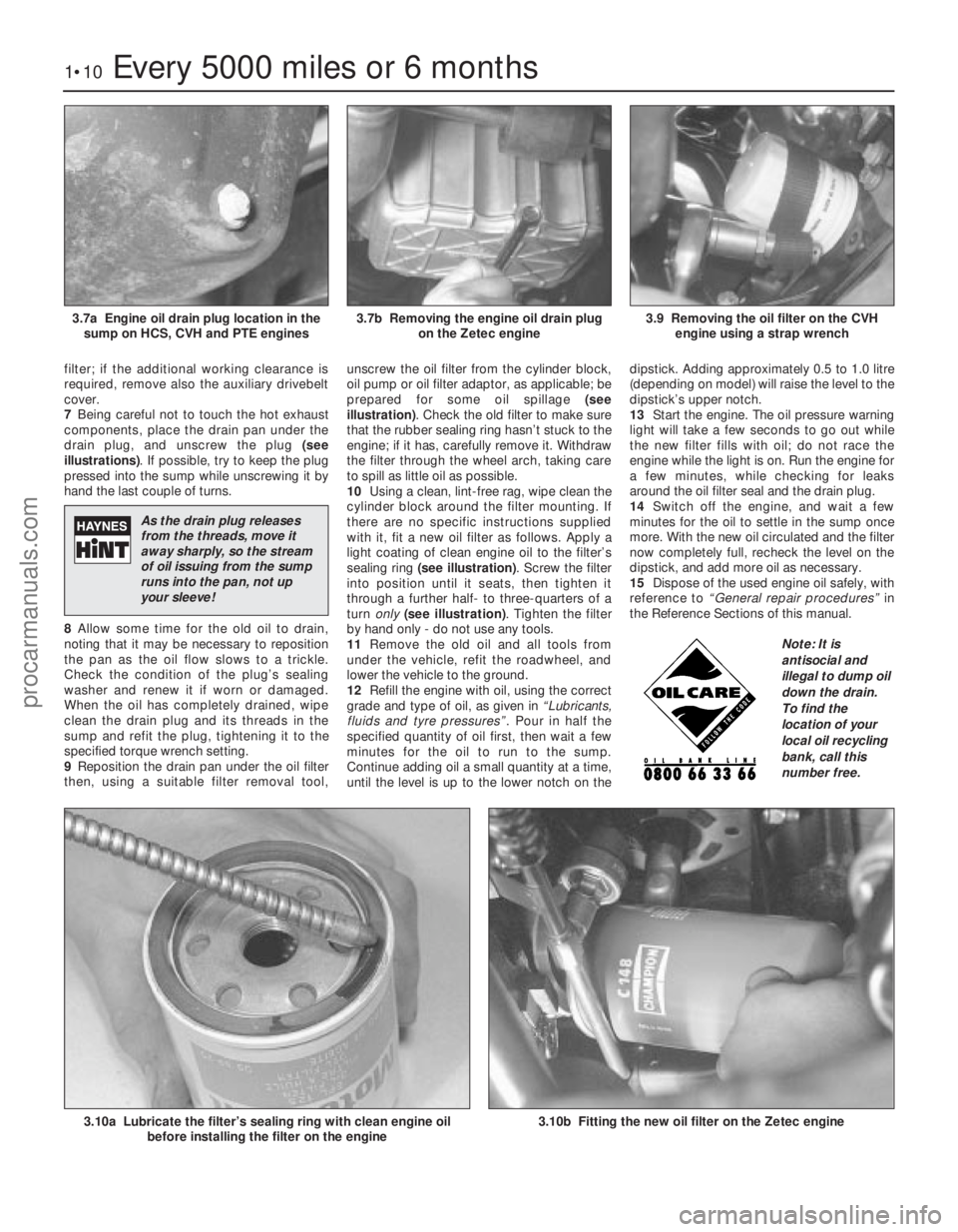
7Being careful not to touch the hot exhaust
components, place the drain pan under the
drain plug, and unscrew the plug (see
illustrations) . If possible, try to keep the plug
pressed into the sump while unscrewing it by
hand the last couple of turns.
8 Allow some time for the old oil to drain,
noting that it may be necessary to reposition
the pan as the oil flow slows to a trickle.
Check the condition of the plug’s sealing
washer and renew it if worn or damaged.
When the oil has completely drained, wipe
clean the drain plug and its threads in the
sump and refit the plug, tightening it to the
specified torque wrench setting.
9 Reposition the drain pan under the oil filter
then, using a suitable filter removal tool, unscrew the oil filter from the cylinder block,
oil pump or oil filter adaptor, as applicable; be
prepared for some oil spillage
(see
illustration) . Check the old filter to make sure
that the rubber sealing ring hasn’t stuck to the
engine; if it has, carefully remove it. Withdraw
the filter through the wheel arch, taking care
to spill as little oil as possible.
10 Using a clean, lint-free rag, wipe clean the
cylinder block around the filter mounting. If
there are no specific instructions supplied
with it, fit a new oil filter as follows. Apply a
light coating of clean engine oil to the filter’s
sealing ring (see illustration) . Screw the filter
into position until it seats, then tighten it
through a further half- to three-quarters of a
turn only (see illustration) . Tighten the filter
by hand only - do not use any tools.
11 Remove the old oil and all tools from
under the vehicle, refit the roadwheel, and
lower the vehicle to the ground.
12 Refill the engine with oil, using the correct
grade and type of oil, as given in “Lubricants,
fluids and tyre pressures” . Pour in half the
specified quantity of oil first, then wait a few
minutes for the oil to run to the sump.
Continue adding oil a small quantity at a time,
until the level is up to the lower notch on the dipstick. Adding approximately 0.5 to 1.0 litre
(depending on model) will raise the level to the
dipstick’s upper notch.
13
Start the engine. The oil pressure warning
light will take a few seconds to go out while
the new filter fills with oil; do not race the
engine while the light is on. Run the engine for
a few minutes, while checking for leaks
around the oil filter seal and the drain plug.
14 Switch off the engine, and wait a few
minutes for the oil to settle in the sump once
more. With the new oil circulated and the filter
now completely full, recheck the level on the
dipstick, and add more oil as necessary.
15 Dispose of the used engine oil safely, with
reference to “General repair procedures” in
the Reference Sections of this manual.
1•10Every 5000 miles or 6 months
3.10b Fitting the new oil filter on the Zetec engine 3.10a Lubricate the filter’s sealing ring with clean engine oil before installing the filter on the engine
3.9 Removing the oil filter on the CVHengine using a strap wrench3.7b Removing the engine oil drain plug on the Zetec engine3.7a Engine oil drain plug location in thesump on HCS, CVH and PTE engines
1595Ford Fiesta Remake
Note: It is
antisocial and
illegal to dump oil
down the drain.
To find the
location of your
local oil recycling
bank, call this
number free.
As the drain plug releases
from the threads, move it
away sharply, so the stream
of oil issuing from the sump
runs into the pan, not up
your sleeve!
procarmanuals.com
http://vnx.su
Page 22 of 296
23 Coolant renewal
1
Note: If the antifreeze used is Ford’s own, the
coolant need not be renewed for the life of the
vehicle. If the vehicle’s history is unknown, if
antifreeze of lesser quality is known to be in
the system, or simply if you prefer to follow
conventional servicing intervals, the coolant
should be changed periodically (typically,
every 3 years) as described here. Refer also to
“Antifreeze - notes on renewal” in this
Section.
Warning: Do not allow
antifreeze to come in contact
with your skin or painted
surfaces of the vehicle. Flush
contaminated areas immediately with
plenty of water. Don’t store new coolant,
or leave old coolant lying around, where
it’s accessible to children or pets - they’re
attracted by its sweet smell. Ingestion of
even a small amount of coolant can be
fatal! Wipe up garage-floor and drip-pan
spills immediately. Keep antifreeze
containers covered, and repair cooling
system leaks as soon as they’re noticed.
Warning: Never remove the expansion
tank filler cap when the engine is running,
or has just been switched off, as the
cooling system will be hot, and the
consequent escaping steam and scalding
coolant could cause serious injury.
Coolant draining
Warning: Wait until the engine is
cold before starting this
procedure.
1 To drain the system, first remove the
expansion tank filler cap (see “Weekly
Checks” ).
2 If additional working clearance is required,
raise the front of the vehicle and support it securely on axle stands (see
“Jacking and
Vehicle Support” ).
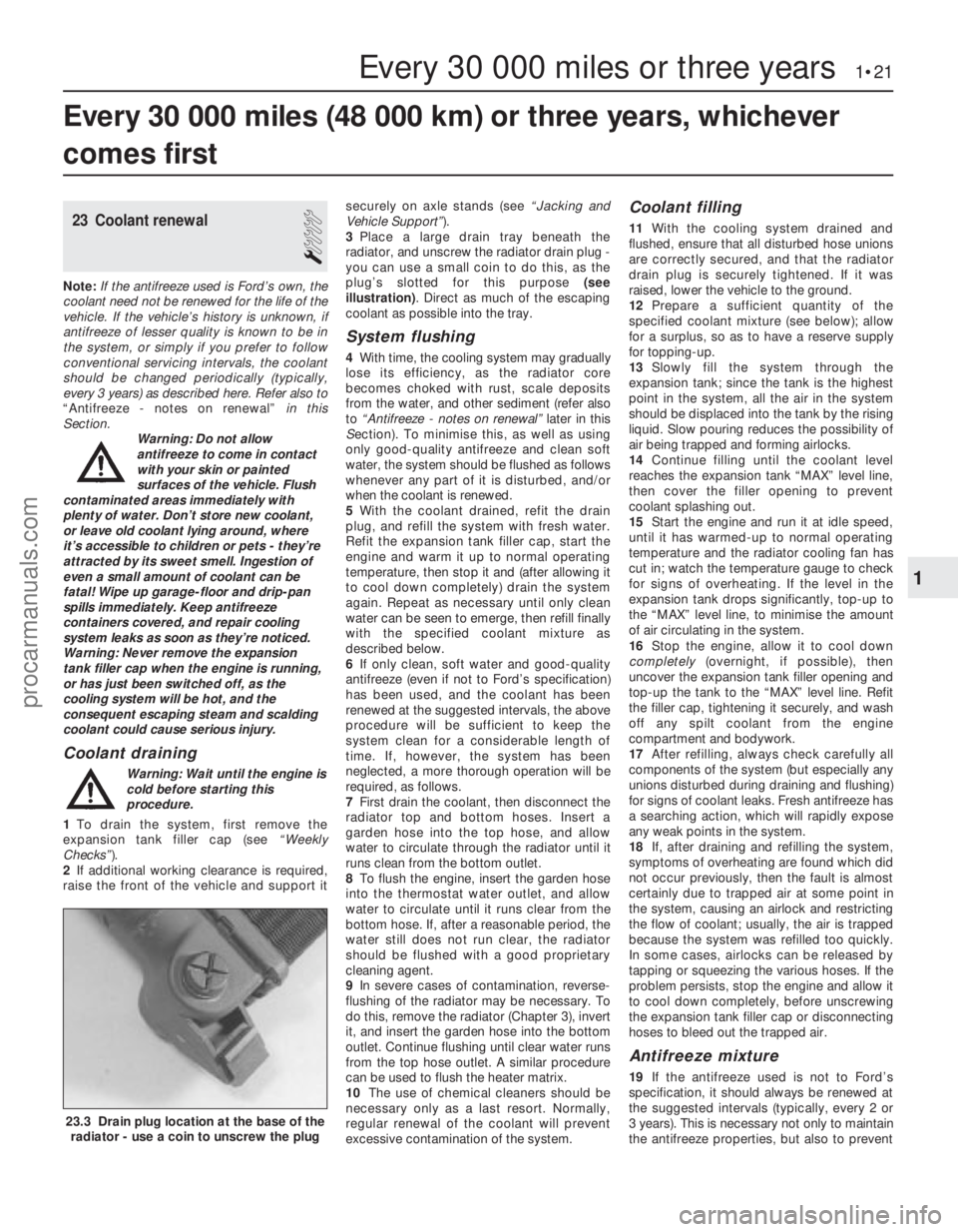
3 Place a large drain tray beneath the
radiator, and unscrew the radiator drain plug -
you can use a small coin to do this, as the
plug’s slotted for this purpose (see
illustration) . Direct as much of the escaping
coolant as possible into the tray.
System flushing
4 With time, the cooling system may gradually
lose its efficiency, as the radiator core
becomes choked with rust, scale deposits
from the water, and other sediment (refer also
to “Antifreeze - notes on renewal” later in this
S ection). To minimise this, as well as using
only good-quality antifreeze and clean soft
water, the system should be flushed as follows
whenever any part of it is disturbed, and/or
when the coolant is renewed.
5 With the coolant drained, refit the drain
plug, and refill the system with fresh water.
Refit the expansion tank filler cap, start the
engine and warm it up to normal operating
temperature, then stop it and (after allowing it
to cool down completely) drain the system
again. Repeat as necessary until only clean
water can be seen to emerge, then refill finally
with the specified coolant mixture as
described below.
6 If only clean, soft water and good-quality
antifreeze (even if not to Ford’s specification)
has been used, and the coolant has been
renewed at the suggested intervals, the above
procedure will be sufficient to keep the
system clean for a considerable length of
time. If, however, the system has been
neglected, a more thorough operation will be
required, as follows.
7 First drain the coolant, then disconnect the
radiator top and bottom hoses. Insert a
garden hose into the top hose, and allow
water to circulate through the radiator until it
runs clean from the bottom outlet.
8 To flush the engine, insert the garden hose
into the thermostat water outlet, and allow
water to circulate until it runs clear from the
bottom hose. If, after a reasonable period, the
water still does not run clear, the radiator
should be flushed with a good proprietary
cleaning agent.
9 In severe cases of contamination, reverse-
flushing of the radiator may be necessary. To
do this, remove the radiator (Chapter 3), invert
it, and insert the garden hose into the bottom
outlet. Continue flushing until clear water runs
from the top hose outlet. A similar procedure
can be used to flush the heater matrix.
10 The use of chemical cleaners should be
necessary only as a last resort. Normally,
regular renewal of the coolant will prevent
excessive contamination of the system.
Coolant filling
11 With the cooling system drained and
flushed, ensure that all disturbed hose unions
are correctly secured, and that the radiator
drain plug is securely tightened. If it was
raised, lower the vehicle to the ground.
12 Prepare a sufficient quantity of the
specified coolant mixture (see below); allow
for a surplus, so as to have a reserve supply
for topping-up.
13 Slowly fill the system through the
expansion tank; since the tank is the highest
point in the system, all the air in the system
should be displaced into the tank by the rising
liquid. Slow pouring reduces the possibility of
air being trapped and forming airlocks.
14 Continue filling until the coolant level
reaches the expansion tank “MAX” level line,
then cover the filler opening to prevent
coolant splashing out.
15 Start the engine and run it at idle speed,
until it has warmed-up to normal operating
temperature and the radiator cooling fan has
cut in; watch the temperature gauge to check
for signs of overheating. If the level in the
expansion tank drops significantly, top-up to
the “MAX” level line, to minimise the amount
of air circulating in the system.
16 Stop the engine, allow it to cool down
completely (overnight, if possible), then
uncover the expansion tank filler opening and
top-up the tank to the “MAX” level line. Refit
the filler cap, tightening it securely, and wash
off any spilt coolant from the engine
compartment and bodywork.
17 After refilling, always check carefully all
components of the system (but especially any
unions disturbed during draining and flushing)
for signs of coolant leaks. Fresh antifreeze has
a searching action, which will rapidly expose
any weak points in the system.
18 If, after draining and refilling the system,
symptoms of overheating are found which did
not occur previously, then the fault is almost
certainly due to trapped air at some point in
the system, causing an airlock and restricting
the flow of coolant; usually, the air is trapped
because the system was refilled too quickly.
In some cases, airlocks can be released by
tapping or squeezing the various hoses. If the
problem persists, stop the engine and allow it
to cool down completely, before unscrewing
the expansion tank filler cap or disconnecting
hoses to bleed out the trapped air.
Antifreeze mixture
19 If the antifreeze used is not to Ford’s
specification, it should always be renewed at
the suggested intervals (typically, every 2 or
3 years). This is necessary not only to maintain
the antifreeze properties, but also to prevent
Every 30 000 miles (48 000 km) or three years, whichever
comes first
Every 30 000 miles or three years 1•21
23.3 Drain plug location at the base of the radiator - use a coin to unscrew the plug
1
1595Ford Fiesta Remakeprocarmanuals.com
http://vnx.su
Page 32 of 296
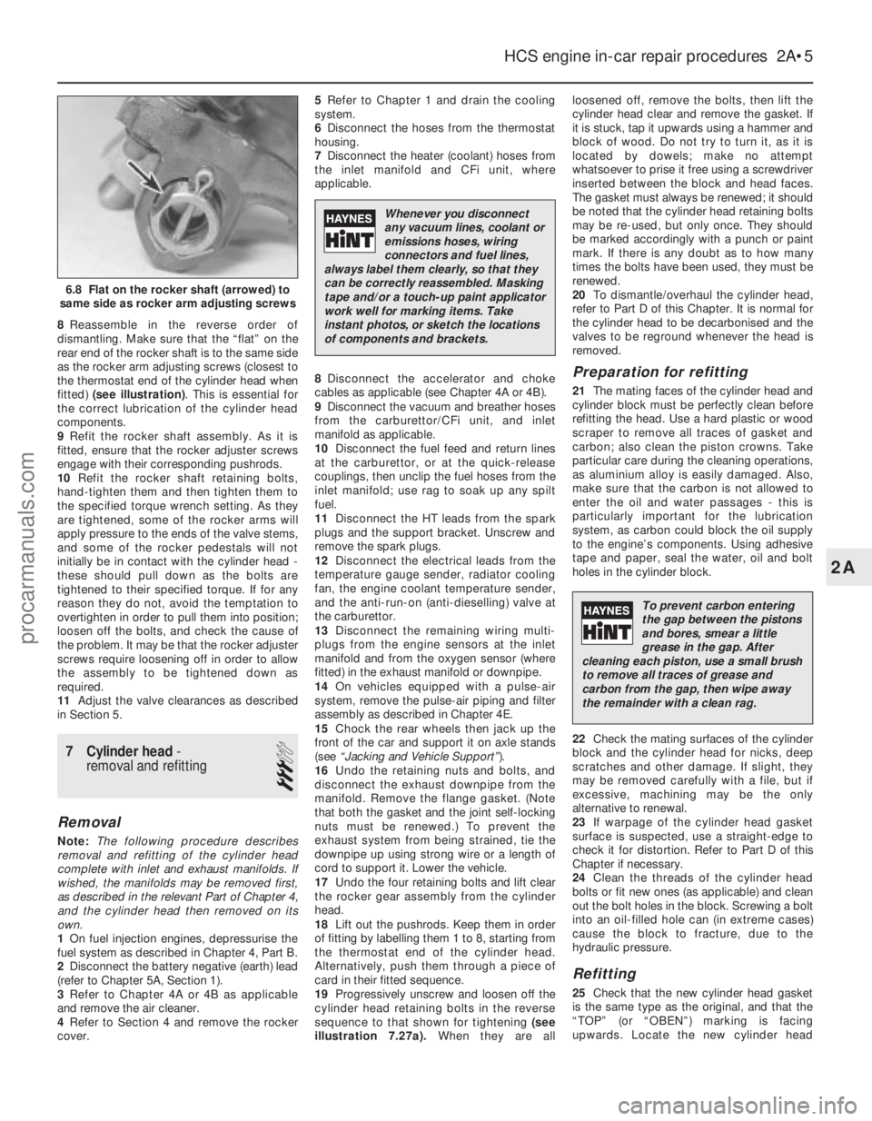
8Reassemble in the reverse order of
dismantling. Make sure that the “flat” on the
rear end of the rocker shaft is to the same side
as the rocker arm adjusting screws (closest to
the thermostat end of the cylinder head when
fitted) (see illustration) . This is essential for
the correct lubrication of the cylinder head
components.
9 Refit the rocker shaft assembly. As it is
fitted, ensure that the rocker adjuster screws
engage with their corresponding pushrods.
10 Refit the rocker shaft retaining bolts,
hand-tighten them and then tighten them to
the specified torque wrench setting. As they
are tightened, some of the rocker arms will
apply pressure to the ends of the valve stems,
and some of the rocker pedestals will not
initially be in contact with the cylinder head -
these should pull down as the bolts are
tightened to their specified torque. If for any
reason they do not, avoid the temptation to
overtighten in order to pull them into position;
loosen off the bolts, and check the cause of
the problem. It may be that the rocker adjuster
screws require loosening off in order to allow
the assembly to be tightened down as
required.
11 Adjust the valve clearances as described
in Section 5.
7 Cylinder head -
removal and refitting
3
Removal
Note: The following procedure describes
removal and refitting of the cylinder head
complete with inlet and exhaust manifolds. If
wished, the manifolds may be removed first,
as described in the relevant Part of Chapter 4,
and the cylinder head then removed on its
own.
1 On fuel injection engines, depressurise the
fuel system as described in Chapter 4, Part B.
2 Disconnect the battery negative (earth) lead
(refer to Chapter 5A, Section 1).
3 Refer to Chapter 4A or 4B as applicable
and remove the air cleaner.
4 Refer to Section 4 and remove the rocker
cover. 5
Refer to Chapter 1 and drain the cooling
system.
6 Disconnect the hoses from the thermostat
housing.
7 Disconnect the heater (coolant) hoses from
the inlet manifold and CFi unit, where
applicable.
8 Disconnect the accelerator and choke
cables as applicable (see Chapter 4A or 4B).
9 Disconnect the vacuum and breather hoses
from the carburettor/CFi unit, and inlet
manifold as applicable.
10 Disconnect the fuel feed and return lines
at the carburettor, or at the quick-release
couplings, then unclip the fuel hoses from the
inlet manifold; use rag to soak up any spilt
fuel.
11 Disconnect the HT leads from the spark
plugs and the support bracket. Unscrew and
remove the spark plugs.
12 Disconnect the electrical leads from the
temperature gauge sender, radiator cooling
fan, the engine coolant temperature sender,
and the anti-run-on (anti-dieselling) valve at
the carburettor.
13 Disconnect the remaining wiring multi-
plugs from the engine sensors at the inlet
manifold and from the oxygen sensor (where
fitted) in the exhaust manifold or downpipe.
14 On vehicles equipped with a pulse-air
system, remove the pulse-air piping and filter
assembly as described in Chapter 4E.
15 Chock the rear wheels then jack up the
front of the car and support it on axle stands
(see “Jacking and Vehicle Support” ).
16 Undo the retaining nuts and bolts, and
disconnect the exhaust downpipe from the
manifold. Remove the flange gasket. (Note
that both the gasket and the joint self-locking
nuts must be renewed.) To prevent the
exhaust system from being strained, tie the
downpipe up using strong wire or a length of
cord to support it. Lower the vehicle.
17 Undo the four retaining bolts and lift clear
the rocker gear assembly from the cylinder
head.
18 Lift out the pushrods. Keep them in order
of fitting by labelling them 1 to 8, starting from
the thermostat end of the cylinder head.
Alternatively, push them through a piece of
card in their fitted sequence.
19 Progressively unscrew and loosen off the
cylinder head retaining bolts in the reverse
sequence to that shown for tightening (see
illustration 7.27a). When they are all loosened off, remove the bolts, then lift the
cylinder head clear and remove the gasket. If
it is stuck, tap it upwards using a hammer and
block of wood. Do not try to turn it, as it is
located by dowels; make no attempt
whatsoever to prise it free using a screwdriver
inserted between the block and head faces.
The gasket must always be renewed; it should
be noted that the cylinder head retaining bolts
may be re-used, but only once. They should
be marked accordingly with a punch or paint
mark. If there is any doubt as to how many
times the bolts have been used, they must be
renewed.
20
To dismantle/overhaul the cylinder head,
refer to Part D of this Chapter. It is normal for
the cylinder head to be decarbonised and the
valves to be reground whenever the head is
removed.
Preparation for refitting
21 The mating faces of the cylinder head and
cylinder block must be perfectly clean before
refitting the head. Use a hard plastic or wood
scraper to remove all traces of gasket and
carbon; also clean the piston crowns. Take
particular care during the cleaning operations,
as aluminium alloy is easily damaged. Also,
make sure that the carbon is not allowed to
enter the oil and water passages - this is
particularly important for the lubrication
system, as carbon could block the oil supply
to the engine’s components. Using adhesive
tape and paper, seal the water, oil and bolt
holes in the cylinder block.
22 Check the mating surfaces of the cylinder
block and the cylinder head for nicks, deep
scratches and other damage. If slight, they
may be removed carefully with a file, but if
excessive, machining may be the only
alternative to renewal.
23 If warpage of the cylinder head gasket
surface is suspected, use a straight-edge to
check it for distortion. Refer to Part D of this
Chapter if necessary.
24 Clean the threads of the cylinder head
bolts or fit new ones (as applicable) and clean
out the bolt holes in the block. Screwing a bolt
into an oil-filled hole can (in extreme cases)
cause the block to fracture, due to the
hydraulic pressure.
Refitting
25 Check that the new cylinder head gasket
is the same type as the original, and that the
“TOP” (or “OBEN”) marking is facing
upwards. Locate the new cylinder head
HCS engine in-car repair procedures 2A•5
6.8 Flat on the rocker shaft (arrowed) to
same side as rocker arm adjusting screws
2A
1595Ford Fiesta Remake
Whenever you disconnect
any vacuum lines, coolant or
emissions hoses, wiring
connectors and fuel lines,
always label them clearly, so that they
can be correctly reassembled. Masking
tape and/or a touch-up paint applicator
work well for marking items. Take
instant photos, or sketch the locations
of components and brackets.
To prevent carbon entering
the gap between the pistons
and bores, smear a little
grease in the gap. After
cleaning each piston, use a small brush
to remove all traces of grease and
carbon from the gap, then wipe away
the remainder with a clean rag.
procarmanuals.com
http://vnx.su
Page 35 of 296
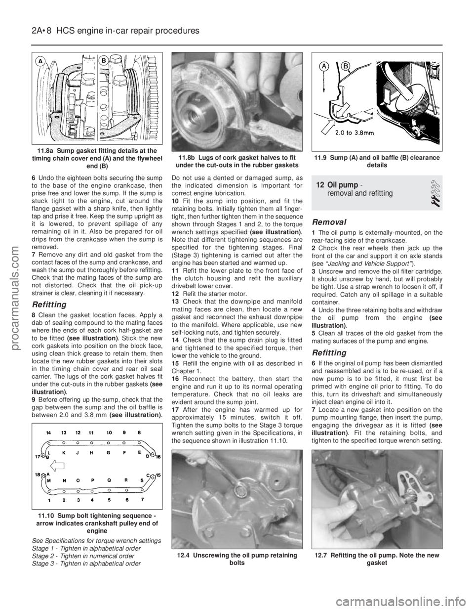
6Undo the eighteen bolts securing the sump
to the base of the engine crankcase, then
prise free and lower the sump. If the sump is
stuck tight to the engine, cut around the
flange gasket with a sharp knife, then lightly
tap and prise it free. Keep the sump upright as
it is lowered, to prevent spillage of any
remaining oil in it. Also be prepared for oil
drips from the crankcase when the sump is
removed.
7 Remove any dirt and old gasket from the
contact faces of the sump and crankcase, and
wash the sump out thoroughly before refitting.
Check that the mating faces of the sump are
not distorted. Check that the oil pick-up
strainer is clear, cleaning it if necessary.
Refitting
8 Clean the gasket location faces. Apply a
dab of sealing compound to the mating faces
where the ends of each cork half-gasket are
to be fitted (see illustration) . Stick the new
cork gaskets into position on the block face,
using clean thick grease to retain them, then
locate the new rubber gaskets into their slots
in the timing chain cover and rear oil seal
carrier. The lugs of the cork gasket halves fit
under the cut-outs in the rubber gaskets (see
illustration) .
9 Before offering up the sump, check that the
gap between the sump and the oil baffle is
between 2.0 and 3.8 mm (see illustration).Do not use a dented or damaged sump, as
the indicated dimension is important for
correct engine lubrication.
10
Fit the sump into position, and fit the
retaining bolts. Initially tighten them all finger-
tight, then further tighten them in the sequence
shown through Stages 1 and 2, to the torque
wrench settings specified (see illustration).
Note that different tightening sequences are
specified for the tightening stages. Final
(Stage 3) tightening is carried out after the
engine has been started and warmed up.
11 Refit the lower plate to the front face of
the clutch housing and refit the auxiliary
drivebelt lower cover.
12 Refit the starter motor.
13 Check that the downpipe and manifold
mating faces are clean, then locate a new
gasket and reconnect the exhaust downpipe
to the manifold. Where applicable, use new
self-locking nuts, and tighten securely.
14 Check that the sump drain plug is fitted
and tightened to the specified torque, then
lower the vehicle to the ground.
15 Refill the engine with oil as described in
Chapter 1.
16 Reconnect the battery, then start the
engine and run it up to its normal operating
temperature. Check that no oil leaks are
evident around the sump joint.
17 After the engine has warmed up for
approximately 15 minutes, switch it off.
Tighten the sump bolts to the Stage 3 torque
wrench setting given in the Specifications, in
the sequence shown in illustration 11.10.
12 Oil pump -
removal and refitting
2
Removal
1 The oil pump is externally-mounted, on the
rear-facing side of the crankcase.
2 Chock the rear wheels then jack up the
front of the car and support it on axle stands
(see “Jacking and Vehicle Support” ).
3 Unscrew and remove the oil filter cartridge.
It should unscrew by hand, but will probably
be tight. Use a strap wrench to loosen it off, if
required. Catch any oil spillage in a suitable
container.
4 Undo the three retaining bolts and withdraw
the oil pump from the engine (see
illustration) .
5 Clean all traces of the old gasket from the
mating surfaces of the pump and engine.
Refitting
6 If the original oil pump has been dismantled
and reassembled and is to be re-used, or if a
new pump is to be fitted, it must first be
primed with engine oil prior to fitting. To do
this, turn its driveshaft and simultaneously
inject clean engine oil into it.
7 Locate a new gasket into position on the
pump mounting flange, then insert the pump,
engaging the drivegear as it is fitted (see
illustration) . Fit the retaining bolts, and
tighten to the specified torque wrench setting.
2A•8 HCS engine in-car repair procedures
12.7 Refitting the oil pump. Note the new gasket12.4 Unscrewing the oil pump retaining bolts
11.10 Sump bolt tightening sequence -
arrow indicates crankshaft pulley end of
engine
See Specifications for torque wrench settings
Stage 1 - Tighten in alphabetical order
Stage 2 - Tighten in numerical order
Stage 3 - Tighten in alphabetical order
11.9 Sump (A) and oil baffle (B) clearance details11.8b Lugs of cork gasket halves to fit
under the cut-outs in the rubber gaskets11.8a Sump gasket fitting details at the
timing chain cover end (A) and the flywheel end (B)
1595Ford Fiesta Remakeprocarmanuals.com
http://vnx.su
Page 36 of 296
8Fit a new oil filter into position on
the oil pump body, as described in Chap-
ter 1.
9 Lower the vehicle to the ground, and top-
up the engine oil as described in “Weekly
Checks”.
13 Oil pump - dismantling,
inspection and reassembly
3
Dismantling
1 To inspect the oil pump components for
excessive wear, undo the retaining bolts and
remove the cover plate from the pump body.
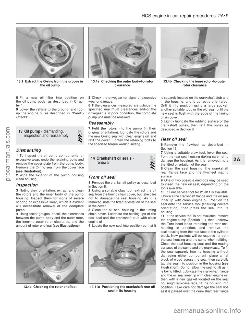
Remove the O-ring seal from the cover face
(see illustration) .
2 Wipe the exterior of the pump housing
clean housing.
Inspection
3 Noting their orientation, extract and clean
the rotors and the inner body of the pump
housing. Inspect them for signs of severe
scoring or excessive wear, which if evident
will necessitate renewal of the complete
pump.
4 Using feeler gauges, check the clearances
between the pump body and the outer rotor,
the inner-to-outer rotor clearance, and the
amount of rotor endfloat (see illustrations).5
Check the drivegear for signs of excessive
wear or damage.
6 If the clearances measured are outside the
specified maximum clearances and/or the
drivegear is in poor condition, the complete
pump unit must be renewed.
Reassembly
7 Refit the rotors into the pump (in their
original orientation), lubricate the rotors and
the new O-ring seal with clean engine oil, and
refit the cover. Tighten the retaining bolts to
the specified torque wrench setting.
14 Crankshaft oil seals -
renewal
3
Front oil seal
1 Remove the crankshaft pulley as described
in Section 8.
2 Using a suitable claw tool, extract the oil
seal from the timing chain cover, but take care
not to damage the seal housing. As it is
removed, note the fitted orientation of the seal
in the cover.
3 Clean the oil seal housing in the timing
chain cover. Lubricate the sealing lips of the
new seal and the crankshaft stub with clean
engine oil.
4 Locate the new seal into position so that it is squarely located on the crankshaft stub and
in the housing, and is correctly orientated.
Drift it into position using a large socket,
another suitable tool, or the old seal, until the
new seal is flush with the edge of the timing
chain cover.
5
Lightly lubricate the rubbing surface of the
crankshaft pulley, then refit the pulley as
described in Section 8.
Rear oil seal
6 Remove the flywheel as described in
Section 16.
7 Using a suitable claw tool, lever the seal
from the rear seal housing (taking care not to
damage the housing). As it is removed, note
the fitted orientation of the seal.
8 Clean the seal housing, the crankshaft
rear flange face and the flywheel mating
surface.
9 One of two possible methods may be used
to insert the new oil seal, depending on the
tools available.
10 If Ford service tool No 21-011 is available,
lubricate the crankshaft flange and the oil seal
inner lip with clean engine oil. Position the
seal onto the service tool (ensuring correct
orientation), then press the seal into its
housing.
11 If the service tool is not available, remove
the engine sump (Section 11), then unscrew
the Torx-head bolts retaining the rear seal
housing in position, and remove the
seal housing from the rear face of the cylinder
block. New gaskets will be required for both
the seal housing and the sump when refitting.
Clean the seal housing seat and the mating
surfaces of the sump and the crankcase. To fit
the seal squarely into its housing without
damaging either component, place a flat
block of wood across the seal, then carefully
tap the seal into position in the housing (see
illustration) . Do not allow the seal to tilt as it
is being fitted. Lubricate the crankshaft flange
and the oil seal inner lip with clean engine oil,
then with a new gasket located on the seal
housing/crankcase face, fit the housing into
position. Take care not damage the seal lips
as it is passed over the crankshaft rear flange
HCS engine in-car repair procedures 2A•9
13.4b Checking the inner rotor-to-outer rotor clearance13.4a Checking the outer body-to-rotor clearance13.1 Extract the O-ring from the groove inthe oil pump
14.11a Positioning the crankshaft rear oilseal in its housing13.4c Checking the rotor endfloat
2A
1595Ford Fiesta Remakeprocarmanuals.com
http://vnx.su
Page 83 of 296
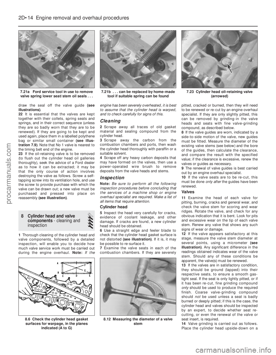
draw the seal off the valve guide (see
illustrations) .
22 It is essential that the valves are kept
together with their collets, spring seats and
springs, and in their correct sequence (unless
they are so badly worn that they are to be
renewed). If they are going to be kept and
used again, place them in a labelled polythene
bag or similar small container (see illus-
tration 7.9) . Note that No 1 valve is nearest to
the timing belt end of the engine.
23 If the oil-retaining valve is to be removed
(to flush out the cylinder head oil galleries
thoroughly), seek the advice of a Ford dealer
as to how it can be extracted; it may be
that the only course of action involves
destroying the valve as follows. Screw a self-
tapping screw into its ventilation hole, and use
the screw to provide purchase with which the
valve can be drawn out; a new valve must be
purchased and pressed into place on
reassembly (see illustration) .
8 Cylinder head and valve
components - cleaning and
inspection
4
1 Thorough cleaning of the cylinder head and
valve components, followed by a detailed
inspection, will enable you to decide how
much valve service work must be carried out
during the engine overhaul. Note:If the engine has been severely overheated, it is best
to assume that the cylinder head is warped,
and to check carefully for signs of this.
Cleaning
2
Scrape away all traces of old gasket
material and sealing compound from the
cylinder head.
3 Scrape away the carbon from the
combustion chambers and ports, then wash
the cylinder head thoroughly with paraffin or a
suitable solvent.
4 Scrape off any heavy carbon deposits that
may have formed on the valves, then use a
power-operated wire brush to remove
deposits from the valve heads and stems.
Inspection
Note: Be sure to perform all the following
inspection procedures before concluding that
the services of a machine shop or engine
overhaul specialist are required. Make a list of
all items that require attention.
Cylinder head
5 Inspect the head very carefully for cracks,
evidence of coolant leakage, and other
damage. If cracks are found, a new cylinder
head should be obtained.
6 Use a straight edge and feeler blade to
check that the cylinder head gasket surface is
not distorted (see illustration) . If it is, it may
be possible to re-surface it.
7 Examine the valve seats in each of the
combustion chambers. If they are severely pitted, cracked or burned, then they will need
to be renewed or re-cut by an engine overhaul
specialist. If they are only slightly pitted, this
can be removed by grinding-in the valve
heads and seats with fine valve-grinding
compound, as described below.
8
If the valve guides are worn, indicated by a
side-to-side motion of the valve, new guides
must be fitted. Measure the diameter of the
existing valve stems (see below) and the bore
of the guides, then calculate the clearance,
and compare the result with the specified
value; if the clearance is excessive, renew the
valves or guides as necessary.
9 The renewal of valve guides is best carried
out by an engine overhaul specialist.
10 If the valve seats are to be re-cut, this
must be done only afterthe guides have been
renewed.
Valves
11 Examine the head of each valve for
pitting, burning, cracks and general wear, and
check the valve stem for scoring and wear
ridges. Rotate the valve, and check for any
obvious indication that it is bent. Look for pits
and excessive wear on the tip of each valve
stem. Renew any valve that shows any such
signs of wear or damage.
12 If the valve appears satisfactory at this
stage, measure the valve stem diameter at
several points, using a micrometer (see
illustration) . Any significant difference in the
readings obtained indicates wear of the valve
stem. Should any of these conditions be
apparent, the valve(s) must be renewed.
13 If the valves are in satisfactory condition,
they should be ground (lapped) into their
respective seats, to ensure a smooth gas-
tight seal. If the seat is only lightly pitted, or if
it has been re-cut, fine grinding compound
only should be used to produce the required
finish. Coarse valve-grinding compound
should notbe used unless a seat is badly
burned or deeply pitted; if this is the case, the
cylinder head and valves should be inspected
by an expert, to decide whether seat re-
cutting, or even the renewal of the valve or
seat insert, is required.
14 Valve grinding is carried out as follows.
Place the cylinder head upside-down on a
2D•14 Engine removal and overhaul procedures
8.12 Measuring the diameter of a valve
stem8.6 Check the cylinder head gasketsurfaces for warpage, in the planes
indicated (A to G)
7.23 Cylinder head oil-retaining valve (arrowed)7.21b . . . can be replaced by home-madetool if suitable spring can be found7.21a Ford service tool in use to removevalve spring lower seat/stem oil seals . . .
1595Ford Fiesta Remakeprocarmanuals.com
http://vnx.su
Page 84 of 296
bench, with a block of wood at each end to
give clearance for the valve stems.
15Smear a trace of (the appropriate grade
of) valve-grinding compound on the seat face,
and press a suction grinding tool onto the
valve head. With a semi-rotary action, grind
the valve head to its seat, lifting the valve
occasionally to redistribute the grinding
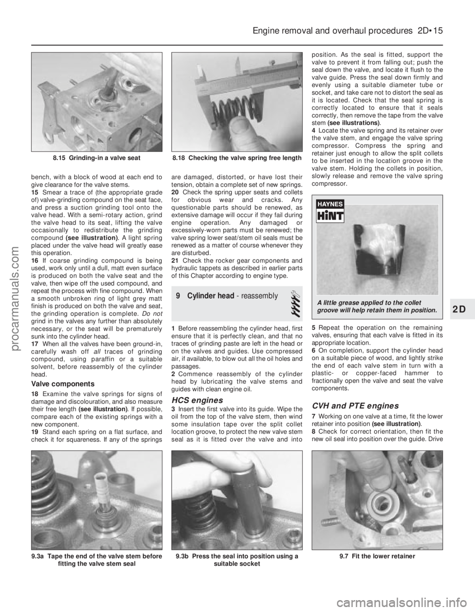
compound (see illustration) . A light spring
placed under the valve head will greatly ease
this operation.
16 If coarse grinding compound is being
used, work only until a dull, matt even surface
is produced on both the valve seat and the
valve, then wipe off the used compound, and
repeat the process with fine compound. When
a smooth unbroken ring of light grey matt
finish is produced on both the valve and seat,
the grinding operation is complete. Do not
grind in the valves any further than absolutely
necessary, or the seat will be prematurely
sunk into the cylinder head.
17 When all the valves have been ground-in,
carefully wash off alltraces of grinding
compound, using paraffin or a suitable
solvent, before reassembly of the cylinder
head.
Valve components
18 Examine the valve springs for signs of
damage and discolouration, and also measure
their free length (see illustration) . If possible,
compare each of the existing springs with a
new component.
19 Stand each spring on a flat surface, and
check it for squareness. If any of the springs are damaged, distorted, or have lost their
tension, obtain a complete set of new springs.
20
Check the spring upper seats and collets
for obvious wear and cracks. Any
questionable parts should be renewed, as
extensive damage will occur if they fail during
engine operation. Any damaged or
excessively-worn parts must be renewed; the
valve spring lower seat/stem oil seals must be
renewed as a matter of course whenever they
are disturbed.
21 Check the rocker gear components and
hydraulic tappets as described in earlier parts
of this Chapter according to engine type.
9 Cylinder head - reassembly
4
1Before reassembling the cylinder head, first
ensure that it is perfectly clean, and that no
traces of grinding paste are left in the head or
on the valves and guides. Use compressed
air, if available, to blow out all the oil holes and
passages.
2 Commence reassembly of the cylinder
head by lubricating the valve stems and
guides with clean engine oil.
HCS engines
3 Insert the first valve into its guide. Wipe the
oil from the top of the valve stem, then wind
some insulation tape over the split collet
location groove, to protect the new valve stem
seal as it is fitted over the valve and into position. As the seal is fitted, support the
valve to prevent it from falling out; push the
seal down the valve, and locate it flush to the
valve guide. Press the seal down firmly and
evenly using a suitable diameter tube or
socket, and take care not to distort the seal as
it is located. Check that the seal spring is
correctly located to ensure that it seals
correctly, then remove the tape from the valve
stem (see illustrations)
.
4 Locate the valve spring and its retainer over
the valve stem, and engage the valve spring
compressor. Compress the spring and
retainer just enough to allow the split collets
to be inserted in the location groove in the
valve stem. Holding the collets in position,
slowly release and remove the valve spring
compressor.
5 Repeat the operation on the remaining
valves, ensuring that each valve is fitted in its
appropriate location.
6 On completion, support the cylinder head
on a suitable piece of wood, and lightly strike
the end of each valve stem in turn with a
plastic- or copper-faced hammer to
fractionally open the valve and seat the valve
components.CVH and PTE engines
7 Working on one valve at a time, fit the lower
retainer into position (see illustration).
8 Check for correct orientation, then fit the
new oil seal into position over the guide. Drive
Engine removal and overhaul procedures 2D•15
9.3a Tape the end of the valve stem before fitting the valve stem seal
8.18 Checking the valve spring free length8.15 Grinding-in a valve seat
9.7 Fit the lower retainer9.3b Press the seal into position using a suitable socket
2D
1595Ford Fiesta Remake
A little grease applied to the collet
groove will help retain them in position.
procarmanuals.com
http://vnx.su