1989 FORD FIESTA washer fluid
[x] Cancel search: washer fluidPage 6 of 296
Maintenance – component location1•5
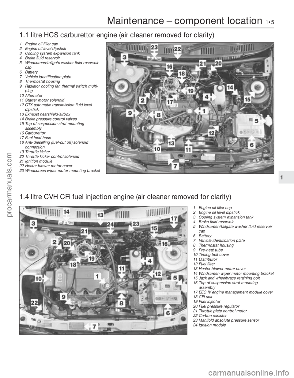
1 Engine oil filler cap
2 Engine oil level dipstick
3 Cooling system expansion tank
4 Brake fluid reservoir
5 Windscreen/tailgate washer fluid reservoircap
6 Battery
7 Vehicle identification plate
8 Thermostat housing
9 Pre-heat tube
10 Timing belt cover
11 Distributor
12 Fuel filter
13 Heater blower motor cover
14 Windscreen wiper motor mounting bracket
15 Jack and wheelbrace retaining bolt
16 Top of suspension strut mounting
assembly
17 EEC IV engine management module cover
18 CFi unit
19 Fuel injector
20 Fuel pressure regulator
21 Throttle plate control motor
22 Carbon canister
23 Manifold absolute pressure sensor
24 Ignition module
1.1 litre HCS carburettor engine (air cleaner removed for clarity)
1
1595Ford Fiesta Remake
1.4 litre CVH CFi fuel injection engine (air cleaner removed for clarity)
1 Engine oil filler cap
2 Engine oil level dipstick
3 Cooling system expansion tank
4 Brake fluid reservoir
5 Windscreen/tailgate washer fluid reservoir
cap
6 Battery
7 Vehicle identification plate
8 Thermostat housing
9 Radiator cooling fan thermal switch multi- plug
10 Alternator
11 Starter motor solenoid
12 CTX automatic transmission fluid level
dipstick
13 Exhaust heatshield/airbox
14 Brake pressure control valves
15 Top of suspension strut mounting
assembly
16 Carburettor
17 Fuel feed hose
18 Anti-dieselling (fuel-cut off) solenoid
connection
19 Throttle kicker
20 Throttle kicker control solenoid
21 Ignition module
22 Heater blower motor cover
23 Windscreen wiper motor mounting bracket
procarmanuals.com
http://vnx.su
Page 7 of 296
1•6Maintenance – component location
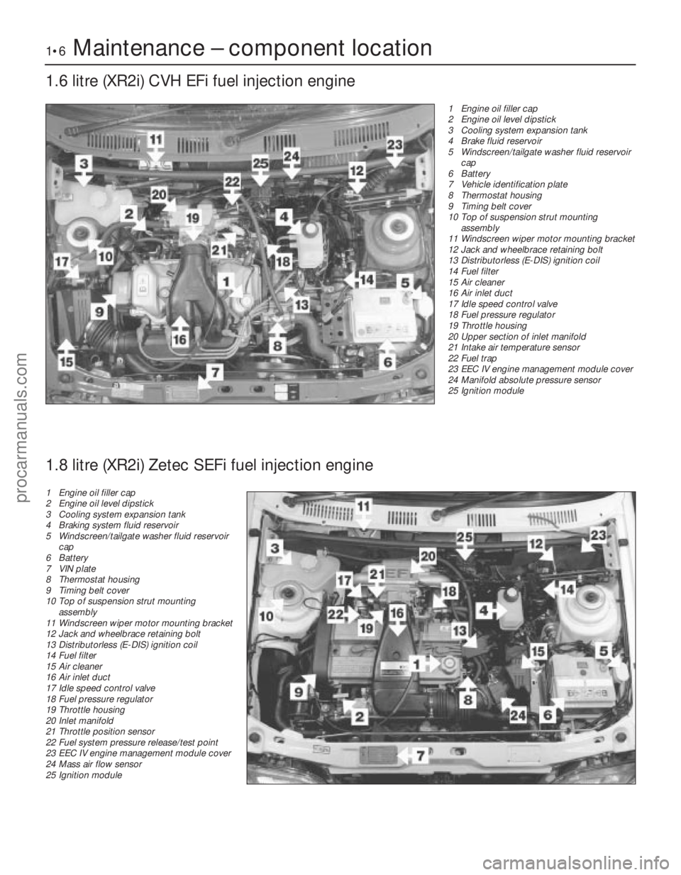
1.6 litre (XR2i) CVH EFi fuel injection engine
1595Ford Fiesta Remake1 Engine oil filler cap
2 Engine oil level dipstick
3 Cooling system expansion tank
4 Brake fluid reservoir
5 Windscreen/tailgate washer fluid reservoir
cap
6 Battery
7 Vehicle identification plate
8 Thermostat housing
9 Timing belt cover
10 Top of suspension strut mounting
assembly
11 Windscreen wiper motor mounting bracket
12 Jack and wheelbrace retaining bolt
13 Distributorless (E-DIS) ignition coil
14 Fuel filter
15 Air cleaner
16 Air inlet duct
17 Idle speed control valve
18 Fuel pressure regulator
19 Throttle housing
20 Upper section of inlet manifold
21 Intake air temperature sensor
22 Fuel trap
23 EEC IV engine management module cover
24 Manifold absolute pressure sensor
25 Ignition module
1.8 litre (XR2i) Zetec SEFi fuel injection engine
1 Engine oil filler cap
2 Engine oil level dipstick
3 Cooling system expansion tank
4 Braking system fluid reservoir
5 Windscreen/tailgate washer fluid reservoir
cap
6 Battery
7 VIN plate
8 Thermostat housing
9 Timing belt cover
10 Top of suspension strut mounting
assembly
11 Windscreen wiper motor mounting bracket
12 Jack and wheelbrace retaining bolt
13 Distributorless (E-DIS) ignition coil
14 Fuel filter
15 Air cleaner
16 Air inlet duct
17 Idle speed control valve
18 Fuel pressure regulator
19 Throttle housing
20 Inlet manifold
21 Throttle position sensor
22 Fuel system pressure release/test point
23 EEC IV engine management module cover
24 Mass air flow sensor
25 Ignition module
procarmanuals.com
http://vnx.su
Page 11 of 296
filter; if the additional working clearance is
required, remove also the auxiliary drivebelt
cover.
7Being careful not to touch the hot exhaust
components, place the drain pan under the
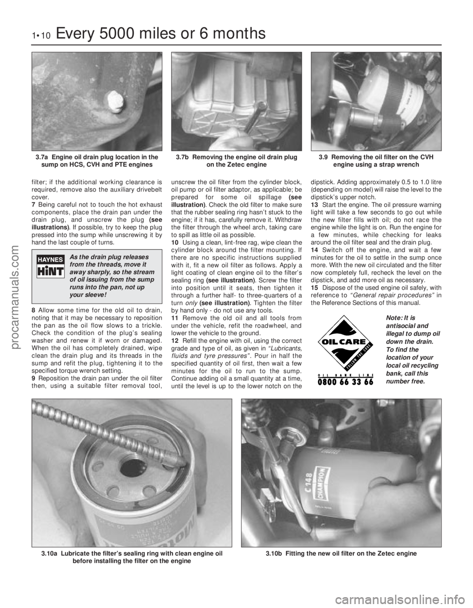
drain plug, and unscrew the plug (see
illustrations) . If possible, try to keep the plug
pressed into the sump while unscrewing it by
hand the last couple of turns.
8 Allow some time for the old oil to drain,
noting that it may be necessary to reposition
the pan as the oil flow slows to a trickle.
Check the condition of the plug’s sealing
washer and renew it if worn or damaged.
When the oil has completely drained, wipe
clean the drain plug and its threads in the
sump and refit the plug, tightening it to the
specified torque wrench setting.
9 Reposition the drain pan under the oil filter
then, using a suitable filter removal tool, unscrew the oil filter from the cylinder block,
oil pump or oil filter adaptor, as applicable; be
prepared for some oil spillage
(see
illustration) . Check the old filter to make sure
that the rubber sealing ring hasn’t stuck to the
engine; if it has, carefully remove it. Withdraw
the filter through the wheel arch, taking care
to spill as little oil as possible.
10 Using a clean, lint-free rag, wipe clean the
cylinder block around the filter mounting. If
there are no specific instructions supplied
with it, fit a new oil filter as follows. Apply a
light coating of clean engine oil to the filter’s
sealing ring (see illustration) . Screw the filter
into position until it seats, then tighten it
through a further half- to three-quarters of a
turn only (see illustration) . Tighten the filter
by hand only - do not use any tools.
11 Remove the old oil and all tools from
under the vehicle, refit the roadwheel, and
lower the vehicle to the ground.
12 Refill the engine with oil, using the correct
grade and type of oil, as given in “Lubricants,
fluids and tyre pressures” . Pour in half the
specified quantity of oil first, then wait a few
minutes for the oil to run to the sump.
Continue adding oil a small quantity at a time,
until the level is up to the lower notch on the dipstick. Adding approximately 0.5 to 1.0 litre
(depending on model) will raise the level to the
dipstick’s upper notch.
13
Start the engine. The oil pressure warning
light will take a few seconds to go out while
the new filter fills with oil; do not race the
engine while the light is on. Run the engine for
a few minutes, while checking for leaks
around the oil filter seal and the drain plug.
14 Switch off the engine, and wait a few
minutes for the oil to settle in the sump once
more. With the new oil circulated and the filter
now completely full, recheck the level on the
dipstick, and add more oil as necessary.
15 Dispose of the used engine oil safely, with
reference to “General repair procedures” in
the Reference Sections of this manual.
1•10Every 5000 miles or 6 months
3.10b Fitting the new oil filter on the Zetec engine 3.10a Lubricate the filter’s sealing ring with clean engine oil before installing the filter on the engine
3.9 Removing the oil filter on the CVHengine using a strap wrench3.7b Removing the engine oil drain plug on the Zetec engine3.7a Engine oil drain plug location in thesump on HCS, CVH and PTE engines
1595Ford Fiesta Remake
Note: It is
antisocial and
illegal to dump oil
down the drain.
To find the
location of your
local oil recycling
bank, call this
number free.
As the drain plug releases
from the threads, move it
away sharply, so the stream
of oil issuing from the sump
runs into the pan, not up
your sleeve!
procarmanuals.com
http://vnx.su
Page 14 of 296
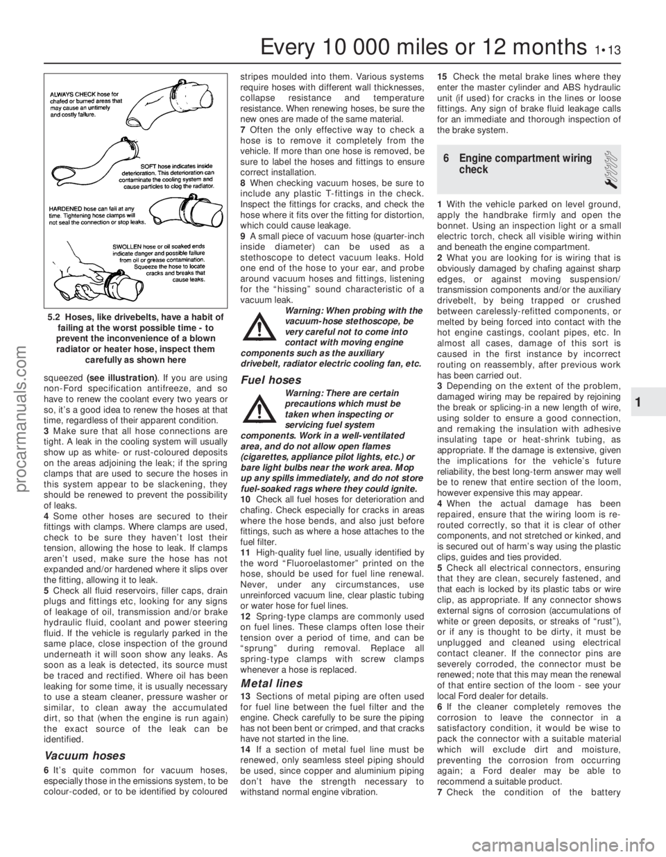
squeezed (see illustration) . If you are using
non-Ford specification antifreeze, and so
have to renew the coolant every two years or
so, it’s a good idea to renew the hoses at that
time, regardless of their apparent condition.
3 Make sure that all hose connections are
tight. A leak in the cooling system will usually
show up as white- or rust-coloured deposits
on the areas adjoining the leak; if the spring
clamps that are used to secure the hoses in
this system appear to be slackening, they
should be renewed to prevent the possibility
of leaks.
4 Some other hoses are secured to their
fittings with clamps. Where clamps are used,
check to be sure they haven’t lost their
tension, allowing the hose to leak. If clamps
aren’t used, make sure the hose has not
expanded and/or hardened where it slips over
the fitting, allowing it to leak.
5 Check all fluid reservoirs, filler caps, drain
plugs and fittings etc, looking for any signs
of leakage of oil, transmission and/or brake
hydraulic fluid, coolant and power steering
fluid. If the vehicle is regularly parked in the
same place, close inspection of the ground
underneath it will soon show any leaks. As
soon as a leak is detected, its source must
be traced and rectified. Where oil has been
leaking for some time, it is usually necessary
to use a steam cleaner, pressure washer or
similar, to clean away the accumulated
dirt, so that (when the engine is run again)
the exact source of the leak can be
identified.
Vacuum hoses
6 It’s quite common for vacuum hoses,
especially those in the emissions system, to be
colour-coded, or to be identified by coloured stripes moulded into them. Various systems
require hoses with different wall thicknesses,
collapse resistance and temperature
resistance. When renewing hoses, be sure the
new ones are made of the same material.
7
Often the only effective way to check a
hose is to remove it completely from the
vehicle. If more than one hose is removed, be
sure to label the hoses and fittings to ensure
correct installation.
8 When checking vacuum hoses, be sure to
include any plastic T-fittings in the check.
Inspect the fittings for cracks, and check the
hose where it fits over the fitting for distortion,
which could cause leakage.
9 A small piece of vacuum hose (quarter-inch
inside diameter) can be used as a
stethoscope to detect vacuum leaks. Hold
one end of the hose to your ear, and probe
around vacuum hoses and fittings, listening
for the “hissing” sound characteristic of a
vacuum leak. Warning: When probing with the
vacuum-hose stethoscope, be
very careful not to come into
contact with moving engine
components such as the auxiliary
drivebelt, radiator electric cooling fan, etc.
Fuel hoses
Warning: There are certain
precautions which must be
taken when inspecting or
servicing fuel system
components. Work in a well-ventilated
area, and do not allow open flames
(cigarettes, appliance pilot lights, etc.) or
bare light bulbs near the work area. Mop
up any spills immediately, and do not store
fuel-soaked rags where they could ignite.
10 Check all fuel hoses for deterioration and
chafing. Check especially for cracks in areas
where the hose bends, and also just before
fittings, such as where a hose attaches to the
fuel filter.
11 High-quality fuel line, usually identified by
the word “Fluoroelastomer” printed on the
hose, should be used for fuel line renewal.
Never, under any circumstances, use
unreinforced vacuum line, clear plastic tubing
or water hose for fuel lines.
12 Spring- type clamps are commonly used
on fuel lines. These clamps often lose their
tension over a period of time, and can be
“sprung” during removal. Replace all
spring- type clamps with screw clamps
whenever a hose is replaced.
Metal lines
13 Sections of metal piping are often used
for fuel line between the fuel filter and the
engine. Check carefully to be sure the piping
has not been bent or crimped, and that cracks
have not started in the line.
14 If a section of metal fuel line must be
renewed, only seamless steel piping should
be used, since copper and aluminium piping
don’t have the strength necessary to
withstand normal engine vibration. 15
Check the metal brake lines where they
enter the master cylinder and ABS hydraulic
unit (if used) for cracks in the lines or loose
fittings. Any sign of brake fluid leakage calls
for an immediate and thorough inspection of
the brake system.
6 Engine compartment wiring check
1
1With the vehicle parked on level ground,
apply the handbrake firmly and open the
bonnet. Using an inspection light or a small
electric torch, check all visible wiring within
and beneath the engine compartment.
2 What you are looking for is wiring that is
obviously damaged by chafing against sharp
edges, or against moving suspension/
transmission components and/or the auxiliary
drivebelt, by being trapped or crushed
between carelessly-refitted components, or
melted by being forced into contact with the
hot engine castings, coolant pipes, etc. In
almost all cases, damage of this sort is
caused in the first instance by incorrect
routing on reassembly, after previous work
has been carried out.
3 Depending on the extent of the problem,
damaged wiring may be repaired by rejoining
the break or splicing-in a new length of wire,
using solder to ensure a good connection,
and remaking the insulation with adhesive
insulating tape or heat-shrink tubing, as
appropriate. If the damage is extensive, given
the implications for the vehicle’s future
reliability, the best long-term answer may well
be to renew that entire section of the loom,
however expensive this may appear.
4 When the actual damage has been
repaired, ensure that the wiring loom is re-
routed correctly, so that it is clear of other
components, and not stretched or kinked, and
is secured out of harm’s way using the plastic
clips, guides and ties provided.
5 Check all electrical connectors, ensuring
that they are clean, securely fastened, and
that each is locked by its plastic tabs or wire
clip, as appropriate. If any connector shows
external signs of corrosion (accumulations of
white or green deposits, or streaks of “rust”),
or if any is thought to be dirty, it must be
unplugged and cleaned using electrical
contact cleaner. If the connector pins are
severely corroded, the connector must be
renewed; note that this may mean the renewal
of that entire section of the loom - see your
local Ford dealer for details.
6 If the cleaner completely removes the
corrosion to leave the connector in a
satisfactory condition, it would be wise to
pack the connector with a suitable material
which will exclude dirt and moisture,
preventing the corrosion from occurring
again; a Ford dealer may be able to
recommend a suitable product.
7 Check the condition of the battery
Every 10 000 miles or 12 months1•13
5.2 Hoses, like drivebelts, have a habit of
failing at the worst possible time - to
prevent the inconvenience of a blown radiator or heater hose, inspect them
carefully as shown here
1
1595Ford Fiesta Remakeprocarmanuals.com
http://vnx.su
Page 44 of 296
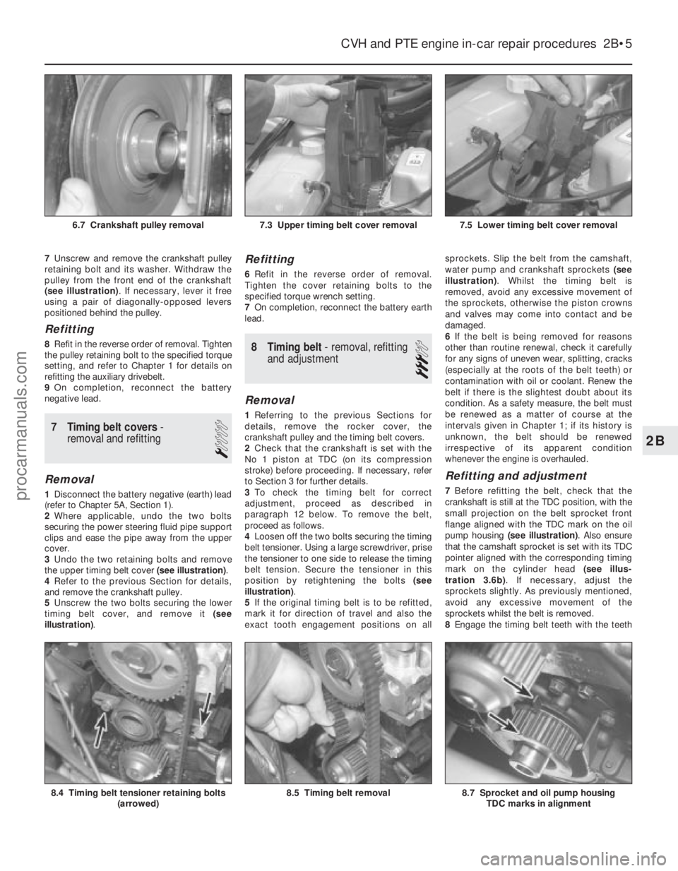
7Unscrew and remove the crankshaft pulley
retaining bolt and its washer. Withdraw the
pulley from the front end of the crankshaft
(see illustration) . If necessary, lever it free
using a pair of diagonally-opposed levers
positioned behind the pulley.
Refitting
8 Refit in the reverse order of removal. Tighten
the pulley retaining bolt to the specified torque
setting, and refer to Chapter 1 for details on
refitting the auxiliary drivebelt.
9 On completion, reconnect the battery
negative lead.
7 Timing belt covers -
removal and refitting
1
Removal
1 Disconnect the battery negative (earth) lead
(refer to Chapter 5A, Section 1).
2 Where applicable, undo the two bolts
securing the power steering fluid pipe support
clips and ease the pipe away from the upper
cover.
3 Undo the two retaining bolts and remove
the upper timing belt cover (see illustration).
4 Refer to the previous Section for details,
and remove the crankshaft pulley.
5 Unscrew the two bolts securing the lower
timing belt cover, and remove it (see
illustration) .
Refitting
6Refit in the reverse order of removal.
Tighten the cover retaining bolts to the
specified torque wrench setting.
7 On completion, reconnect the battery earth
lead.
8 Timing belt - removal, refitting
and adjustment
3
Removal
1 Referring to the previous Sections for
details, remove the rocker cover, the
crankshaft pulley and the timing belt covers.
2 Check that the crankshaft is set with the
No 1 piston at TDC (on its compression
stroke) before proceeding. If necessary, refer
to Section 3 for further details.
3 To check the timing belt for correct
adjustment, proceed as described in
paragraph 12 below. To remove the belt,
proceed as follows.
4 Loosen off the two bolts securing the timing
belt tensioner. Using a large screwdriver, prise
the tensioner to one side to release the timing
belt tension. Secure the tensioner in this
position by retightening the bolts (see
illustration) .
5 If the original timing belt is to be refitted,
mark it for direction of travel and also the
exact tooth engagement positions on all sprockets. Slip the belt from the camshaft,
water pump and crankshaft sprockets
(see
illustration) . Whilst the timing belt is
removed, avoid any excessive movement of
the sprockets, otherwise the piston crowns
and valves may come into contact and be
damaged.
6 If the belt is being removed for reasons
other than routine renewal, check it carefully
for any signs of uneven wear, splitting, cracks
(especially at the roots of the belt teeth) or
contamination with oil or coolant. Renew the
belt if there is the slightest doubt about its
condition. As a safety measure, the belt must
be renewed as a matter of course at the
intervals given in Chapter 1; if its history is
unknown, the belt should be renewed
irrespective of its apparent condition
whenever the engine is overhauled.
Refitting and adjustment
7 Before refitting the belt, check that the
crankshaft is still at the TDC position, with the
small projection on the belt sprocket front
flange aligned with the TDC mark on the oil
pump housing (see illustration) . Also ensure
that the camshaft sprocket is set with its TDC
pointer aligned with the corresponding timing
mark on the cylinder head (see illus-
tration 3.6b) . If necessary, adjust the
sprockets slightly. As previously mentioned,
avoid any excessive movement of the
sprockets whilst the belt is removed.
8 Engage the timing belt teeth with the teeth
CVH and PTE engine in-car repair procedures 2B•5
7.5 Lower timing belt cover removal7.3 Upper timing belt cover removal6.7 Crankshaft pulley removal
8.7 Sprocket and oil pump housing
TDC marks in alignment8.5 Timing belt removal8.4 Timing belt tensioner retaining bolts (arrowed)
2B
1595Ford Fiesta Remakeprocarmanuals.com
http://vnx.su
Page 57 of 296
clamp brackets and disconnect the pipe joint
union over the top of the cylinder head cover.
Place absorbent rags beneath the union as it
is disconnected to soak up escaping fluid and
plug the open unions to prevent dirt entry and
further fluid loss. Move the pipe(s) clear just
sufficiently to allow removal of the cylinder
head cover.
5Remove the timing belt upper cover (see
Section 7).
6 Disconnect the crankcase breather hose
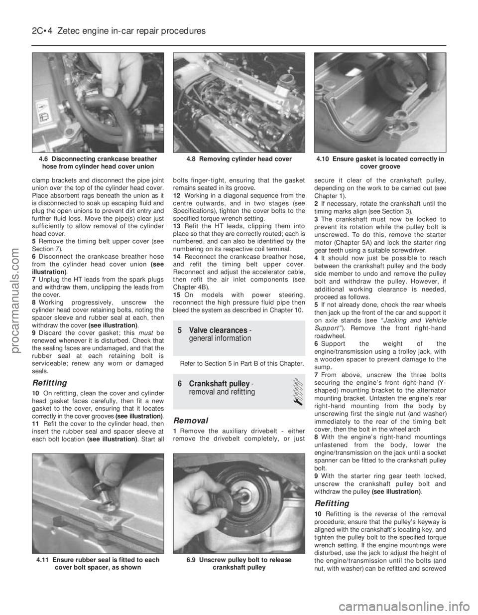
from the cylinder head cover union (see
illustration) .
7 Unplug the HT leads from the spark plugs
and withdraw them, unclipping the leads from
the cover.
8 Working progressively, unscrew the
cylinder head cover retaining bolts, noting the
spacer sleeve and rubber seal at each, then
withdraw the cover (see illustration).
9 Discard the cover gasket; this mustbe
renewed whenever it is disturbed. Check that
the sealing faces are undamaged, and that the
rubber seal at each retaining bolt is
serviceable; renew any worn or damaged
seals.
Refitting
10 On refitting, clean the cover and cylinder
head gasket faces carefully, then fit a new
gasket to the cover, ensuring that it locates
correctly in the cover grooves (see illustration).
11 Refit the cover to the cylinder head, then
insert the rubber seal and spacer sleeve at
each bolt location (see illustration). Start allbolts finger-tight, ensuring that the gasket
remains seated in its groove.
12
Working in a diagonal sequence from the
centre outwards, and in two stages (see
Specifications), tighten the cover bolts to the
specified torque wrench setting.
13 Refit the HT leads, clipping them into
place so that they are correctly routed; each is
numbered, and can also be identified by the
numbering on its respective coil terminal.
14 Reconnect the crankcase breather hose,
and refit the timing belt upper cover.
Reconnect and adjust the accelerator cable,
then refit the air inlet components (see
Chapter 4B).
15 On models with power steering,
reconnect the high pressure fluid pipe then
bleed the system as described in Chapter 10.
5 Valve clearances -
general information
Refer to Section 5 in Part B of this Chapter.
6 Crankshaft pulley -
removal and refitting
1
Removal
1 Remove the auxiliary drivebelt - either
remove the drivebelt completely, or just secure it clear of the crankshaft pulley,
depending on the work to be carried out (see
Chapter 1).
2
If necessary, rotate the crankshaft until the
timing marks align (see Section 3).
3 The crankshaft must now be locked to
prevent its rotation while the pulley bolt is
unscrewed. To do this, remove the starter
motor (Chapter 5A) and lock the starter ring
gear teeth using a suitable screwdriver.
4 It should now just be possible to reach
between the crankshaft pulley and the body
side member to undo and remove the pulley
bolt and withdraw the pulley. However, if
additional working clearance is needed,
proceed as follows.
5 If not already done, chock the rear wheels
then jack up the front of the car and support it
on axle stands (see “Jacking and Vehicle
Support” ). Remove the front right-hand
roadwheel.
6 Support the weight of the
engine/transmission using a trolley jack, with
a wooden spacer to prevent damage to the
sump.
7 From above, unscrew the three bolts
securing the engine’s front right-hand (Y-
shaped) mounting bracket to the alternator
mounting bracket. Unfasten the engine’s rear
right-hand mounting from the body by
unscrewing first the single nut (and washer)
immediately to the rear of the timing belt
cover, then the bolt in the wheel arch
8 With the engine’s right-hand mountings
unfastened from the body, lower the
engine/transmission on the jack until a socket
spanner can be fitted to the crankshaft pulley
bolt.
9 With the starter ring gear teeth locked,
unscrew the crankshaft pulley bolt and
withdraw the pulley (see illustration).
Refitting
10Refitting is the reverse of the removal
procedure; ensure that the pulley’s keyway is
aligned with the crankshaft’s locating key, and
tighten the pulley bolt to the specified torque
wrench setting. If the engine mountings were
disturbed, use the jack to adjust the height of
the engine/transmission until the bolts (and
nut, with washer) can be refitted and screwed
2C•4 Zetec engine in-car repair procedures
6.9 Unscrew pulley bolt to release
crankshaft pulley4.11 Ensure rubber seal is fitted to eachcover bolt spacer, as shown
4.10 Ensure gasket is located correctly in cover groove4.8 Removing cylinder head cover
1595Ford Fiesta Remake
4.6 Disconnecting crankcase breather
hose from cylinder head cover unionprocarmanuals.com
http://vnx.su
Page 79 of 296
25Unscrew the retaining bolt, and detach
the shift rod stabiliser from the transmission.
As it is detached, note the washer located
between the stabiliser and the transmission.
Tie the stabiliser and the shift rod up out of
the way.
Automatic transmission models
26 Unclip and detach the wiring connector
from the starter inhibitor switch (on the
transmission housing).
27 Referring to the relevant Part of Chapter 4
for details, unhook the accelerator (cam plate)
cable from the carburettor or fuel injection unit
(as applicable) at the transmission end of
the cable. Undo the retaining bolt and
detach the cable sheath bracket from the
transmission. Detach the cam plate cable
from the link.
28 Undo the two nuts from the selector cable
bracket which connects it to the lever on the
selector shaft. Disconnect the yoke from the
lever on the selector shaft and the cable from
the lever.
29 Unscrew the union nuts, and disconnect
the oil cooler feed and return pipes from the
transmission. Allow for a certain amount of
spillage, and plug the connections to prevent
the ingress of dirt.
All models
30 Unscrew the retaining nut and withdraw
the Torx-type clamp bolt securing the lower
suspension arm to the spindle carrier on each
side.
31 Refer to Chapter 10 for details, and
detach the right-hand and left-hand track rod
end balljoints from the spindle carriers.
32 On vehicles fitted with the anti-lock
braking system, refer to Chapter 9 and release
the right-hand modulator from its mounting
bracket without disconnecting the rigid brake
pipes or return hose. Tie the modulator
securely to the bulkhead. Additionally, undo
the three bolts securing the modulator
bracket.
33 Insert a suitable lever between the right-
hand driveshaft inner joint and the
transmission housing, and prise free the
driveshaft from the transmission; be prepared
for oil spillage from the transmission case
through the vacated driveshaft aperture. As it
is being prised free, simultaneously pull the
roadwheel outwards on that side, to enable
the driveshaft inboard end to separate
from the transmission. Once it is free,
suspend and support the driveshaft from the
steering gear, to prevent unnecessary strain
being placed on the driveshaft joints.
34 Insert a suitable plastic plug (or if
available, an old driveshaft joint), into the
transmission driveshaft aperture, to
immobilise the gears of the differential unit.
35 Proceed as described above in
paragraphs 33 and 34, and disconnect the
left-hand driveshaft from the transmission.
36 Connect a suitable lift hoist and sling to
the engine, connecting to the lifting eyes. When securely connected, take the weight of
the engine/transmission unit so that the
tension is relieved from the mountings.
37
Undo the retaining bolts and nuts and
detach the right-hand engine mounting from
the vehicle body.
38 Undo the four bolts securing the
transmission bearer to the underside of the
vehicle body. The transmission bearer is
removed with the engine/transmission
assembly.
39 Unscrew the three retaining bolts, and
remove the auxiliary drivebelt cover from
under the crankshaft pulley.
40 The engine/transmission unit should now
be ready for removal from the vehicle. Check
that all of the associated connections and
fittings are disconnected from the engine and
transmission, and positioned out of the way.
41 Enlist the aid of an assistant to help
steady and guide the power unit down
through the engine compartment as it is
removed. If available, position a suitable
engine trolley or crawler board under the
engine/transmission so that when lowered,
the power unit can be withdrawn from the
front end of the vehicle, and then moved to
the area where it is to be cleaned and
dismantled. On automatic transmission
models, particular care must be taken not to
damage the transmission fluid pan (sump)
during the removal and subsequent refitting
processes.
42 Carefully lower the engine and
transmission unit, ensuring that no fittings
become snagged. Detach the hoist and
remove the power unit from under the vehicle.
43 Referring to the relevant Part of Chapter 7,
separate the transmission from the engine.
44 While the engine/transmission is removed,
check the mountings; renew them if they are
worn or damaged. Similarly, check the
condition of all coolant and vacuum hoses
and pipes (see Chapter 1). Components that
are normally hidden can now be checked
properly, and should be renewed if there is
any doubt at all about their condition. Where
the vehicle is fitted with manual transmission,
take the opportunity to inspect the clutch
components (see Chapter 6). It is regarded by
many as good working practice to renew the
clutch assembly as a matter of course,
whenever major engine overhaul work is
carried out. Check also the condition of all
components (such as the transmission oil
seals) disturbed on removal, and renew any
that are damaged or worn.
Refitting
45 Refitting is a reversal of removal, however
note the following additional points:
a) Refer to the applicable Chapters and Sections as for removal.
b) Fit new spring clips to the grooves in the
inboard end of the right- and left-hand
driveshaft joints. Lubricate the splines
with transmission oil prior to fitting. c) Renew the exhaust flange gasket when
reconnecting the exhaust. Ensure that all
wires are routed clear of the exhaust
system and, on catalytic converter
models, ensure that the heat shields are
securely and correctly fitted.
d) Ensure that all earth lead connections are
clean and securely made.
e) Tighten all nuts and bolts to the specified torque.
f) Fit a new oil filter, and refill the engine and transmission with oil, with reference to
Chapter 1.
g) Refill the cooling system with reference to Chapter 1.
h) Refit the alternator and starter motor with reference to Chapter 5A.
i) Where applicable, refit the power steering pump with reference to Chapter 10.
46 When engine and transmission refitting is
complete, refer to the procedures described
in Section 19 before restarting the engine.
5 Engine/transmission -
removal and refitting
(Zetec engines)
3
Warning: Petrol is extremely
flammable, so take extra
precautions when disconnecting
any part of the fuel system.
Don’t smoke, or allow naked flames or
bare light bulbs, in or near the work area,
and don’t work in a garage where a
natural-gas appliance (such as a clothes
dryer or water heater) is installed. If you
spill petrol on your skin, rinse it off
immediately. Have a fire extinguisher rated
for petrol fires handy, and know how to
use it.
Note: Read through the entire Section, as well
as reading the advice in Section 2, before
beginning this procedure. The engine and
transmission are removed as a unit, lowered to
the ground and removed from underneath,
then separated outside the vehicle.
Removal
1 Park the vehicle on firm, level ground, apply
the handbrake firmly, and slacken the nuts
securing both front roadwheels.
2 Depressurise the fuel system as described
in Chapter 4D.
3 Disconnect the battery negative (earth) lead
(refer to Chapter 5A, Section 1).
4 Place protective covers on the wings, then
remove the bonnet (see Chapter 11).
5 Drain the cooling system and the engine oil
(see Chapter 1).
6 Remove the air inlet components and the
complete air cleaner assembly as described in
Chapter 4D.
7 Equalise the pressure in the fuel tank by
removing the filler cap, then release the fuel
feed and return quick-release couplings, and
pull the hoses off the fuel pipes. Plug or cap
all open fittings.
2D•10 Engine removal and overhaul procedures
1595Ford Fiesta Remakeprocarmanuals.com
http://vnx.su
Page 81 of 296
25On automatic transmission models, clean
around the unions, then disconnect the fluid
pipes from the transmission. Plug the
openings in the transmission and the pipe
unions after removal.
26 Refer to Chapter 10 and remove the front
suspension crossmember.
27 Unscrew the nuts to disconnect the
exhaust system front downpipe from the
manifold. Undo the nuts securing the catalytic
converter to the rear part of the exhaust
system, and remove the converter and
downpipe assembly.
28 On vehicles fitted with the anti-lock braking
system, refer to Chapter 9 and release the
right-hand modulator from its mounting
bracket without disconnecting the rigid brake
pipes or return hose. Tie the modulator
securely to the bulkhead. Additionally, undo
the three bolts securing the modulator bracket.
29 Disconnect both anti-roll bar links from
their respective suspension struts, and both
track rod end ball joints from their spindle
carriers (see Chapter 10).
30 Unscrew the retaining nut and withdraw
the Torx-type clamp bolt securing the lower
suspension arm to the spindle carrier on each
side.
31 Insert a suitable lever between the right-
hand driveshaft inner joint and the
transmission housing, and prise free the
driveshaft from the transmission; be prepared
for oil spillage from the transmission case
through the vacated driveshaft aperture. As it
is being prised free, simultaneously pull the
roadwheel outwards on that side to enable the
driveshaft inboard end to separate from the
transmission. Once it is free, suspend and
support the driveshaft from the steering gear,
to prevent unnecessary strain being placed on
the driveshaft joints.
32 Insert a suitable plastic plug (or if
available, an old driveshaft joint), into the
transmission driveshaft aperture, to
immobilise the gears of the differential unit.
33 Proceed as described above in
paragraphs 31 and 32, and disconnect the
left-hand driveshaft from the transmission.
34 Remove the oil filter, referring to Chapter 1
if necessary.
35 Connect a suitable lift hoist and sling to
the engine, connecting to the lift eyes. When
securely connected, take the weight of the
engine/transmission unit so that the tension is
relieved from the mountings.
36 Unbolt the engine rear right-hand
mounting from the body (one bolt in the wheel
arch, one nut in the engine compartment),
then unbolt the engine front right-hand
mounting from the alternator mounting
bracket. Unbolt the transmission bearer from
the underbody.
37 The engine/transmission unit should now
be hanging on the hoist only, with all
components which connect it to the rest of
the vehicle disconnected or removed, and
secured well clear of the unit. Make a final
check that this is the case. 38
Lower the engine/transmission to the
ground, and withdraw it from under the
vehicle.
39 Referring to the relevant Part of Chapter 7,
separate the transmission from the engine.
40 While the engine/transmission is removed,
check the mountings; renew them if they are
worn or damaged. Similarly, check the
condition of all coolant and vacuum hoses
and pipes (see Chapter 1); components that
are normally hidden can now be checked
properly, and should be renewed if there is
any doubt at all about their condition. Where
the vehicle is fitted with manual transmission,
take the opportunity to overhaul the clutch
components (see Chapter 6). It is regarded by
many as good working practice to renew the
clutch assembly as a matter of course,
whenever major engine overhaul work is
carried out. Check also the condition of all
components (such as the transmission oil
seals) disturbed on removal, and renew any
that are damaged or worn.
Refitting
41 Refitting is a reversal of removal, however
note the following additional points:
a) Refer to the applicable Chapters and Sections as for removal.
b) Fit new spring clips to the grooves in the
inboard end of the right- and left-hand
driveshaft joints. Lubricate the splines
with transmission oil prior to fitting.
c) Renew the exhaust flange gaskets when reconnecting the exhaust. Ensure that all
wires are routed clear of the exhaust
system, and that the heat shields are
securely and correctly fitted.
d) Ensure that all earth lead connections are
clean and securely made.
e) Tighten all nuts and bolts to the specified
torque.
f) Fit a new oil filter, and refill the engine and transmission with oil, with reference to
Chapter 1.
g) Refill the cooling system with reference to
Chapter 1.
h) Bleed the power steering system with reference to Chapter 10.
42 When engine and transmission refitting is
complete, refer to the procedures described
in Section 19 before restarting the engine.
6 Engine overhaul - preliminary information
It is much easier to dismantle and work on
the engine if it is mounted on a portable
engine stand. These stands can often be hired
from a tool hire shop. Before the engine is
mounted on a stand, the flywheel/driveplate
should be removed so that the stand bolts
can be tightened into the end of the cylinder
block/crankcase. If a stand is not available, it is possible to
dismantle the engine with it suitably supported on a sturdy, workbench or on the
floor. Be careful not to tip or drop the engine
when working without a stand.
If you intend to obtain a reconditioned
engine, all ancillaries must be removed first, to
be transferred to the replacement engine (just
as they will if you are doing a complete engine
overhaul yourself). These components include
the following:
a) Alternator/power steering pump and
mounting brackets.
b) DIS/E-DIS ignition coil unit (and mounting
bracket), distributor, HT leads and spark
plugs.
c) The thermostat and housing cover.
d) Carburettor/fuel injection system
components.
e) Inlet and exhaust manifolds.
f) Oil filter.
g) Fuel pump.
h) Engine mountings.
i) Flywheel/driveplate.
j) Water pump.
Note: When removing the external
components from the engine, pay close
attention to details that may be helpful or
important during refitting. Note the fitted
positions of gaskets, seals, washers, bolts and
other small items. If you are obtaining a “short” engine
(cylinder block/crankcase, crankshaft, pistons
and connecting rods all assembled), then the
cylinder head, timing chain/belt (together with
tensioner, tensioner and idler pulleys and
covers) sump and oil pump will have to be
removed also. If a complete overhaul is planned, the
engine can be dismantled in the order given
below, referring to Part A, B or C of this
Chapter unless otherwise stated.
a) Inlet and exhaust manifolds.
b) Timing chain/belt, tensioner and
sprockets.
c) Cylinder head.
d) Flywheel/driveplate.
e) Sump.
f) Oil pump.
g) Pistons (with connecting rods).
h) Crankshaft.
i) Camshaft and tappets (HCS engines).
7 Cylinder head - dismantling
4
Note:New and reconditioned cylinder heads
are available from the manufacturers, and from
engine overhaul specialists. Due to the fact
that some specialist tools are required for the
dismantling and inspection procedures, and
new components may not be readily available,
it may be more practical and economical for
the home mechanic to purchase a
reconditioned head, rather than to dismantle,
inspect and recondition the original head.
1 Remove the cylinder head as described in
Part A, B or C of this Chapter (as applicable).
2D•12 Engine removal and overhaul procedures
1595Ford Fiesta Remakeprocarmanuals.com
http://vnx.su