1989 FORD FIESTA wiper fluid
[x] Cancel search: wiper fluidPage 6 of 296
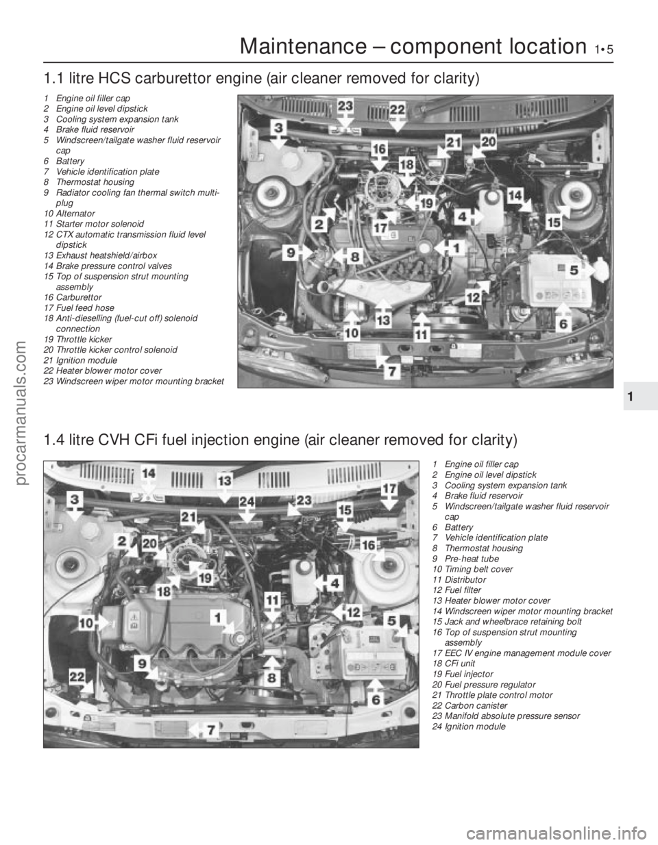
Maintenance – component location1•5
1 Engine oil filler cap
2 Engine oil level dipstick
3 Cooling system expansion tank
4 Brake fluid reservoir
5 Windscreen/tailgate washer fluid reservoircap
6 Battery
7 Vehicle identification plate
8 Thermostat housing
9 Pre-heat tube
10 Timing belt cover
11 Distributor
12 Fuel filter
13 Heater blower motor cover
14 Windscreen wiper motor mounting bracket
15 Jack and wheelbrace retaining bolt
16 Top of suspension strut mounting
assembly
17 EEC IV engine management module cover
18 CFi unit
19 Fuel injector
20 Fuel pressure regulator
21 Throttle plate control motor
22 Carbon canister
23 Manifold absolute pressure sensor
24 Ignition module
1.1 litre HCS carburettor engine (air cleaner removed for clarity)
1
1595Ford Fiesta Remake
1.4 litre CVH CFi fuel injection engine (air cleaner removed for clarity)
1 Engine oil filler cap
2 Engine oil level dipstick
3 Cooling system expansion tank
4 Brake fluid reservoir
5 Windscreen/tailgate washer fluid reservoir
cap
6 Battery
7 Vehicle identification plate
8 Thermostat housing
9 Radiator cooling fan thermal switch multi- plug
10 Alternator
11 Starter motor solenoid
12 CTX automatic transmission fluid level
dipstick
13 Exhaust heatshield/airbox
14 Brake pressure control valves
15 Top of suspension strut mounting
assembly
16 Carburettor
17 Fuel feed hose
18 Anti-dieselling (fuel-cut off) solenoid
connection
19 Throttle kicker
20 Throttle kicker control solenoid
21 Ignition module
22 Heater blower motor cover
23 Windscreen wiper motor mounting bracket
procarmanuals.com
http://vnx.su
Page 7 of 296
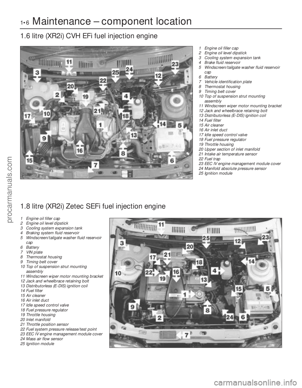
1•6Maintenance – component location
1.6 litre (XR2i) CVH EFi fuel injection engine
1595Ford Fiesta Remake1 Engine oil filler cap
2 Engine oil level dipstick
3 Cooling system expansion tank
4 Brake fluid reservoir
5 Windscreen/tailgate washer fluid reservoir
cap
6 Battery
7 Vehicle identification plate
8 Thermostat housing
9 Timing belt cover
10 Top of suspension strut mounting
assembly
11 Windscreen wiper motor mounting bracket
12 Jack and wheelbrace retaining bolt
13 Distributorless (E-DIS) ignition coil
14 Fuel filter
15 Air cleaner
16 Air inlet duct
17 Idle speed control valve
18 Fuel pressure regulator
19 Throttle housing
20 Upper section of inlet manifold
21 Intake air temperature sensor
22 Fuel trap
23 EEC IV engine management module cover
24 Manifold absolute pressure sensor
25 Ignition module
1.8 litre (XR2i) Zetec SEFi fuel injection engine
1 Engine oil filler cap
2 Engine oil level dipstick
3 Cooling system expansion tank
4 Braking system fluid reservoir
5 Windscreen/tailgate washer fluid reservoir
cap
6 Battery
7 VIN plate
8 Thermostat housing
9 Timing belt cover
10 Top of suspension strut mounting
assembly
11 Windscreen wiper motor mounting bracket
12 Jack and wheelbrace retaining bolt
13 Distributorless (E-DIS) ignition coil
14 Fuel filter
15 Air cleaner
16 Air inlet duct
17 Idle speed control valve
18 Fuel pressure regulator
19 Throttle housing
20 Inlet manifold
21 Throttle position sensor
22 Fuel system pressure release/test point
23 EEC IV engine management module cover
24 Mass air flow sensor
25 Ignition module
procarmanuals.com
http://vnx.su
Page 234 of 296
12
1595Ford Fiesta Remake
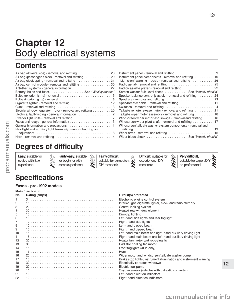
Fuses - pre-1992 models
Main fuse board:
No Rating (amps) Circuit(s) protected
1 3 . . . . . . . . . . . . . . . . . . . . . . . . . . . . . . . . . . . .\
. . . . . . . . . . . . . Electronic engine control system
2 15 . . . . . . . . . . . . . . . . . . . . . . . . . . . . . . . . . . . .\
. . . . . . . . . . . . Interior light, cigarette lighter, clock and radio memory
3 20 . . . . . . . . . . . . . . . . . . . . . . . . . . . . . . . . . . . .\
. . . . . . . . . . . . Central locking system
4 30 . . . . . . . . . . . . . . . . . . . . . . . . . . . . . . . . . . . .\
. . . . . . . . . . . . Heated rear window element
5 10 . . . . . . . . . . . . . . . . . . . . . . . . . . . . . . . . . . . .\
. . . . . . . . . . . . Dim-dip lighting
6 10 . . . . . . . . . . . . . . . . . . . . . . . . . . . . . . . . . . . .\
. . . . . . . . . . . . Left-hand side lights and rear fog light
7 10 . . . . . . . . . . . . . . . . . . . . . . . . . . . . . . . . . . . .\
. . . . . . . . . . . . Right-hand side lights
8 10 . . . . . . . . . . . . . . . . . . . . . . . . . . . . . . . . . . . .\
. . . . . . . . . . . . Left-hand dipped beam
9 10 . . . . . . . . . . . . . . . . . . . . . . . . . . . . . . . . . . . .\
. . . . . . . . . . . . Right-hand dipped beam
10 15 . . . . . . . . . . . . . . . . . . . . . . . . . . . . . . . . . . . .\
. . . . . . . . . . . . Left-hand main beam and right-hand auxiliary driving light
11 15 . . . . . . . . . . . . . . . . . . . . . . . . . . . . . . . . . . . .\
. . . . . . . . . . . . Right-hand main beam and left-hand auxiliary driving light
12 20 . . . . . . . . . . . . . . . . . . . . . . . . . . . . . . . . . . . .\
. . . . . . . . . . . . Heater fan motor and reversing light
13 30 . . . . . . . . . . . . . . . . . . . . . . . . . . . . . . . . . . . .\
. . . . . . . . . . . . Radiator cooling fan motor
14 15 . . . . . . . . . . . . . . . . . . . . . . . . . . . . . . . . . . . .\
. . . . . . . . . . . . Front foglights (XR2i only)
15 15 . . . . . . . . . . . . . . . . . . . . . . . . . . . . . . . . . . . .\
. . . . . . . . . . . . Horn
16 20 . . . . . . . . . . . . . . . . . . . . . . . . . . . . . . . . . . . .\
. . . . . . . . . . . . Wiper motor and windscreen/tailgate washer pump
17 10 . . . . . . . . . . . . . . . . . . . . . . . . . . . . . . . . . . . .\
. . . . . . . . . . . . Brake stop lights, instrument illumination and instrument warning
18 30 . . . . . . . . . . . . . . . . . . . . . . . . . . . . . . . . . . . .\
. . . . . . . . . . . . Electrically operated windows
19 20 . . . . . . . . . . . . . . . . . . . . . . . . . . . . . . . . . . . .\
. . . . . . . . . . . . Electric fuel pump
20 10 . . . . . . . . . . . . . . . . . . . . . . . . . . . . . . . . . . . .\
. . . . . . . . . . . . Oxygen sensor (vehicles with catalytic converter)
21 10 . . . . . . . . . . . . . . . . . . . . . . . . . . . . . . . . . . . .\
. . . . . . . . . . . . Left-hand direction indicators
22 10 . . . . . . . . . . . . . . . . . . . . . . . . . . . . . . . . . . . .\
. . . . . . . . . . . . Right-hand direction indicators
Chapter 12
Body electrical systems
Air bag (driver’s side) - removal and refitting . . . . . . . . . . . . . . . . . . 28
Air bag (passenger’s side) - removal and refitting . . . . . . . . \
. . . . . . . 29
Air bag clock spring - removal and refitting . . . . . . . . . . . . . . . . . . . 31
Air bag control module - removal and refitting . . . . . . . . . . . . . . . . . 30
Anti-theft systems - general information . . . . . . . . . . . . . . . . . . . . . . 27
Battery, bulbs and fuses . . . . . . . . . . . . . . . . . . . .See
“Weekly checks”
Bulbs (exterior lights) - renewal . . . . . . . . . . . . . . . . . . . . . . . . . . . . . 5
Bulbs (interior lights) - renewal . . . . . . . . . . . . . . . . . . . . . . . . . . . . . 6
Cigarette lighter - removal and refitting . . . . . . . . . . . . . . . . . . . . . . 12
Clock - removal and refitting . . . . . . . . . . . . . . . . . . . . . . . . . . . . . . . 13
Electric window regulator motor - removal and refitting . . . . . . . . . . 20
Electrical fault-finding - general information . . . . . . . . . . . . . . . . . . . 2
Exterior light units - removal and refitting . . . . . . . . . . . . . . . . . . . . . 7
Fuses and relays - general information . . . . . . . . . . . . . . . . . . . . . . . 3
General information and precautions . . . . . . . . . . . . . . . . . . . . . . . . 1
Headlight and auxiliary light beam alignment - checking and
adjustment . . . . . . . . . . . . . . . . . . . . . . . . . . . . . . . . . . . .\
. . . . . . . 8
Horn - removal and refitting . . . . . . . . . . . . . . . . . . . . . . . . . . . . . . . 14 Instrument panel - removal and refitting . . . . . . . . . . . . . . . . . . . . . . 9
Instrument panel components - removal and refitting . . . . . . . . . . . 10
“Lights-on” warning module - removal and refitting . . . . . . . . . . . . . 26
Radio aerial - removal and refitting . . . . . . . . . . . . . . . . . . . . . . . . . . 25
Radio/cassette player - removal and refitting . . . . . . . . . . . . . . . . . . 22
Screen washer fluid level check . . . . . . . . . . . . . .See
“Weekly checks”
Speaker balance control joystick - removal and refitting . . . . . . . . . 24
Speakers - removal and refitting . . . . . . . . . . . . . . . . . . . . . . . . . . . . 23
Speedometer cable - removal and refitting . . . . . . . . . . . . . . . . . . . . 11
Switches - removal and refitting . . . . . . . . . . . . . . . . . . . . . . . . . . . . 4
Tailgate remote release motor - removal and refitting . . . . . . . . . . . 21
Tailgate wiper motor assembly - removal and refitting . . . . . . . . . . . 18
Windscreen wiper motor and linkage - removal and refitting . . . . . . 16
Windscreen wiper pivot shaft - removal and refitting . . . . . . . . . . . . 17
Windscreen/tailgate washer system components - removal and refitting . . . . . . . . . . . . . . . . . . . . . . . . . . . . . . . . . . . .\
. . . . . . . . . . 19
Wiper arms - removal and refitting . . . . . . . . . . . . . . . . . . . . . . . . . . 15
Wiper blade check . . . . . . . . . . . . . . . . . . . . . . . .See “Weekly checks”
12•1
Specifications Contents
Easy,suitable for
novice with little
experience Fairly easy,
suitable
for beginner with
some experience Fairly difficult,
suitable for competent
DIY mechanic
Difficult,
suitable for
experienced DIY
mechanic Very difficult,
suitable for expert DIY
or professional
Degrees of difficulty
54321
procarmanuals.com
http://vnx.su
Page 247 of 296
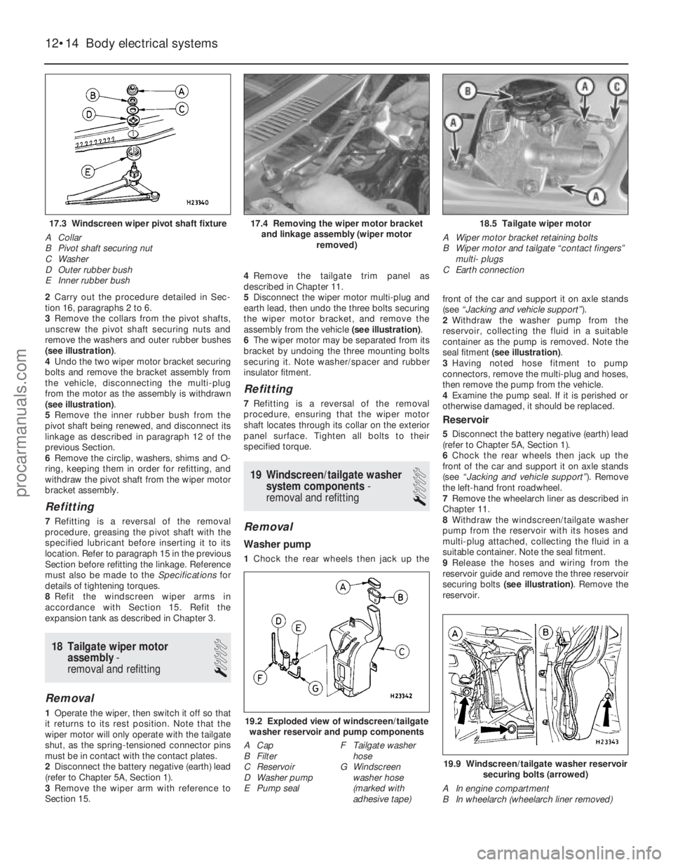
2Carry out the procedure detailed in Sec-
tion 16, paragraphs 2 to 6.
3 Remove the collars from the pivot shafts,
unscrew the pivot shaft securing nuts and
remove the washers and outer rubber bushes
(see illustration) .
4 Undo the two wiper motor bracket securing
bolts and remove the bracket assembly from
the vehicle, disconnecting the multi-plug
from the motor as the assembly is withdrawn
(see illustration) .
5 Remove the inner rubber bush from the
pivot shaft being renewed, and disconnect its
linkage as described in paragraph 12 of the
previous Section.
6 Remove the circlip, washers, shims and O-
ring, keeping them in order for refitting, and
withdraw the pivot shaft from the wiper motor
bracket assembly.
Refitting
7 Refitting is a reversal of the removal
procedure, greasing the pivot shaft with the
specified lubricant before inserting it to its
location. Refer to paragraph 15 in the previous
Section before refitting the linkage. Reference
must also be made to the Specificationsfor
details of tightening torques.
8 Refit the windscreen wiper arms in
accordance with Section 15. Refit the
expansion tank as described in Chapter 3.
18 Tailgate wiper motor assembly -
removal and refitting
1
Removal
1 Operate the wiper, then switch it off so that
it returns to its rest position. Note that the
wiper motor will only operate with the tailgate
shut, as the spring-tensioned connector pins
must be in contact with the contact plates.
2 Disconnect the battery negative (earth) lead
(refer to Chapter 5A, Section 1).
3 Remove the wiper arm with reference to
Section 15. 4
Remove the tailgate trim panel as
described in Chapter 11.
5 Disconnect the wiper motor multi-plug and
earth lead, then undo the three bolts securing
the wiper motor bracket, and remove the
assembly from the vehicle (see illustration).
6 The wiper motor may be separated from its
bracket by undoing the three mounting bolts
securing it. Note washer/spacer and rubber
insulator fitment.
Refitting
7 Refitting is a reversal of the removal
procedure, ensuring that the wiper motor
shaft locates through its collar on the exterior
panel surface. Tighten all bolts to their
specified torque.
19 Windscreen/tailgate washer system components -
removal and refitting
1
Removal
Washer pump
1 Chock the rear wheels then jack up the front of the car and support it on axle stands
(see
“Jacking and vehicle support” ).
2 Withdraw the washer pump from the
reservoir, collecting the fluid in a suitable
container as the pump is removed. Note the
seal fitment (see illustration) .
3 Having noted hose fitment to pump
connectors, remove the multi-plug and hoses,
then remove the pump from the vehicle.
4 Examine the pump seal. If it is perished or
otherwise damaged, it should be replaced.
Reservoir
5 Disconnect the battery negative (earth) lead
(refer to Chapter 5A, Section 1).
6 Chock the rear wheels then jack up the
front of the car and support it on axle stands
(see “Jacking and vehicle support” ). Remove
the left-hand front roadwheel.
7 Remove the wheelarch liner as described in
Chapter 11.
8 Withdraw the windscreen/tailgate washer
pump from the reservoir with its hoses and
multi-plug attached, collecting the fluid in a
suitable container. Note the seal fitment.
9 Release the hoses and wiring from the
reservoir guide and remove the three reservoir
securing bolts (see illustration) . Remove the
reservoir.
12•14 Body electrical systems
19.9 Windscreen/tailgate washer reservoir
securing bolts (arrowed)
A In engine compartment
B In wheelarch (wheelarch liner removed)
19.2 Exploded view of windscreen/tailgate washer reservoir and pump components
A Cap
B Filter
C Reservoir
D Washer pump
E Pump seal F Tailgate washer
hose
G Windscreen
washer hose
(marked with
adhesive tape)
18.5 Tailgate wiper motor
A Wiper motor bracket retaining bolts
B Wiper motor and tailgate “contact fingers” multi- plugs
C Earth connection17.4 Removing the wiper motor bracket and linkage assembly (wiper motor removed)17.3 Windscreen wiper pivot shaft fixture
A Collar
B Pivot shaft securing nut
C Washer
D Outer rubber bush
E Inner rubber bush
1595Ford Fiesta Remakeprocarmanuals.com
http://vnx.su
Page 277 of 296
1595 Ford Fiesta Remake
MOT test checksREF•11
REF
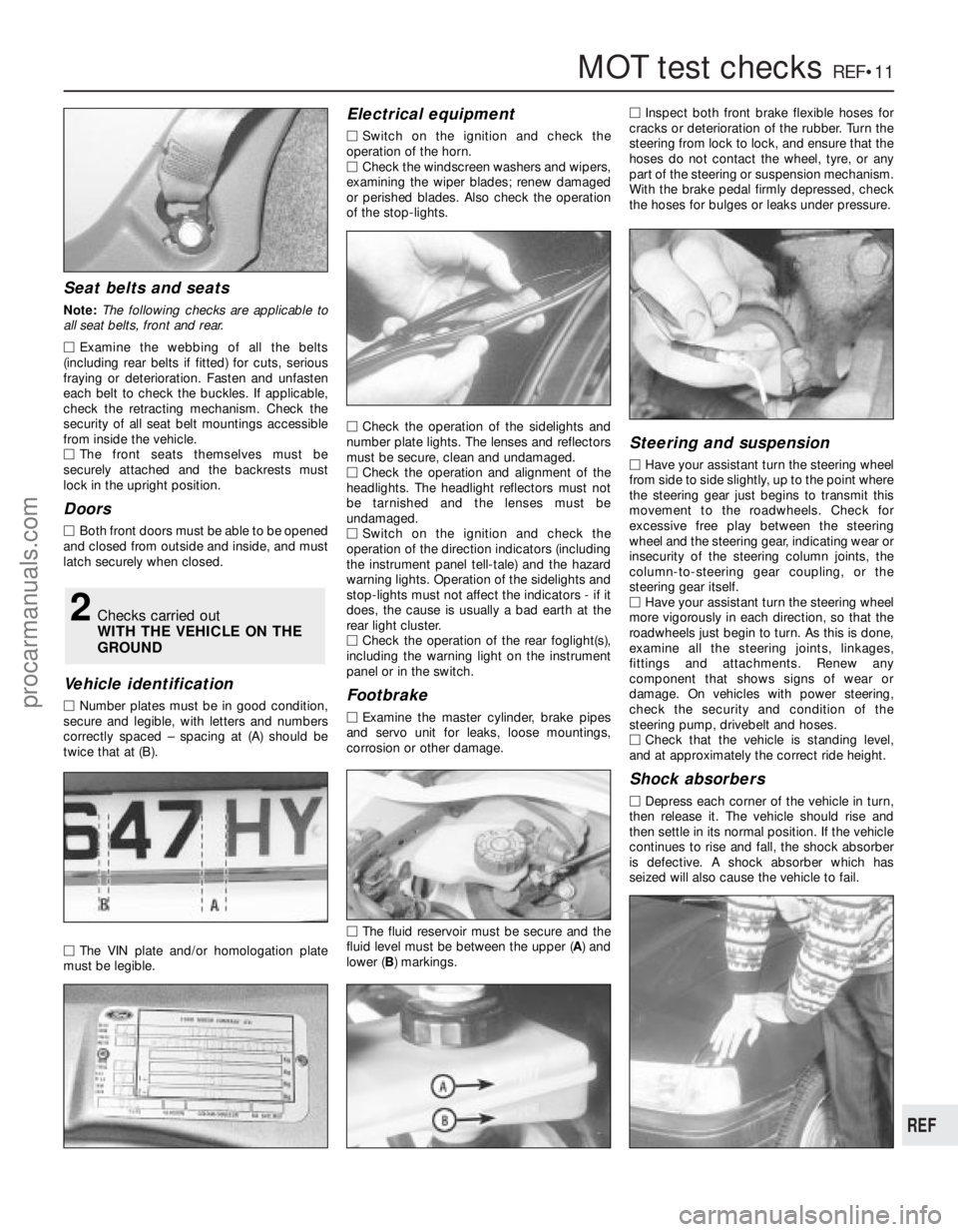
Seat belts and seats
Note: The following checks are applicable to
all seat belts, front and rear.
M Examine the webbing of all the belts
(including rear belts if fitted) for cuts, serious
fraying or deterioration. Fasten and unfasten
each belt to check the buckles. If applicable,
check the retracting mechanism. Check the
security of all seat belt mountings accessible
fr om inside the vehicle.
M The front seats themselves must be
secur ely attached and the backrests must
lock in the upright position.
Doors
M Both front doors must be able to be opened
and closed from outside and inside, and must
latch securely when closed.
V ehicle identification
M Number plates must be in good condition,
secur e and legible, with letters and numbers
corr ectly spaced – spacing at (A) should be
twice that at (B).
M The VIN plate and/or homologation plate
must be legible.
Electrical equipment
M Switch on the ignition and check the
operation of the horn.
M Check the windscreen washers and wipers,
examining the wiper blades; renew damaged
or perished blades. Also check the operation
of the stop-lights.
M Check the operation of the sidelights and
number plate lights. The lenses and reflectors
must be secure, clean and undamaged.
M Check the operation and alignment of the
headlights. The headlight reflectors must not
be tarnished and the lenses must be
undamaged.
M Switch on the ignition and check the
operation of the direction indicators (including
the instrument panel tell-tale) and the hazard
war ning lights. Operation of the sidelights and
stop-lights must not affect the indicators - if it
does, the cause is usually a bad earth at the
r ear light cluster.
M Check the operation of the rear foglight(s),
including the warning light on the instrument
panel or in the switch.
Footbrake
M Examine the master cylinder, brake pipes
and servo unit for leaks, loose mountings,
corr osion or other damage.
M The fluid reservoir must be secure and the
fluid level must be between the upper ( A) and
lower ( B) markings. M
Inspect both front brake flexible hoses for
cracks or deterioration of the rubber . Turn the
steering from lock to lock, and ensure that the
hoses do not contact the wheel, tyre, or any
part of the steering or suspension mechanism.
With the brake pedal firmly depressed, check
the hoses for bulges or leaks under pressure.
Steering and suspension
M Have your assistant turn the steering wheel
fr om side to side slightly, up to the point where
the steering gear just begins to transmit this
movement to the roadwheels. Check for
excessive free play between the steering
wheel and the steering gear, indicating wear or
insecurity of the steering column joints, the
column-to-steering gear coupling, or the
steering gear itself.
M Have your assistant turn the steering wheel
mor e vigorously in each direction, so that the
r oadwheels just begin to turn. As this is done,
examine all the steering joints, linkages,
fittings and attachments. Renew any
component that shows signs of wear or
damage. On vehicles with power steering,
check the security and condition of the
steering pump, drivebelt and hoses.
M Check that the vehicle is standing level,
and at approximately the correct ride height.
Shock absorbers
M Depr ess each corner of the vehicle in turn,
then release it. The vehicle should rise and
then settle in its normal position. If the vehicle
continues to rise and fall, the shock absorber
is defective. A shock absorber which has
seized will also cause the vehicle to fail.
2Checks carried out
WITH THE VEHICLE ON THE
GROUND
procarmanuals.com
http://vnx.su
Page 280 of 296
The vehicle owner who does his or her own
maintenance according to the recommended
service schedules should not have to use this
section of the manual very often. Modern
component reliability is such that, provided
those items subject to wear or deterioration
are inspected or renewed at the specified
intervals, sudden failure is comparatively rare.
Faults do not usually just happen as a result of
sudden failure, but develop over a period of
time. Major mechanical failures in particular are usually preceded by characteristic
symptoms over hundreds or even thousands
of miles. Those components which do
occasionally fail without warning are often
small and easily carried in the vehicle.
With any fault-finding, the first step is to
decide where to begin investigations.
Sometimes this is obvious, but on other
occasions, a little detective work will be
necessary. The owner who makes half a
dozen haphazard adjustments or replacements may be successful in curing a
fault (or its symptoms), but will be none the
wiser if the fault recurs, and ultimately may
have spent more time and money than was
necessary. A calm and logical approach will
be found to be more satisfactory in the long
run. Always take into account any warning
signs or abnormalities that may have been
noticed in the period preceding the fault -
power loss, high or low gauge readings,
unusual smells, etc - and remember that
Engine
m
m
Engine backfires
m
m Engine difficult to start when cold
m
m Engine difficult to start when hot
m
m Engine fails to rotate when attempting to start
m
m Engine hesitates on acceleration
m
m Engine idles erratically
m
m Engine lacks power
m
m Engine misfires at idle speed
m
m Engine misfires throughout the driving speed range
m
m Engine noises
m
m Engine rotates, but will not start
m
m Engine runs-on after switching off
m
m Engine stalls
m
m Engine starts, but stops immediately
m
m Oil pressure warning light illuminated with engine running
m
m Starter motor noisy or excessively-rough in engagement
Cooling system
m
mCorrosion
m
m External coolant leakage
m
m Internal coolant leakage
m
m Overcooling
m
m Overheating
Fuel and exhaust systems
m
mExcessive fuel consumption
m
m Excessive noise or fumes from exhaust system
m
m Fuel leakage and/or fuel odour
Clutch
m
mClutch fails to disengage (unable to select gears)
m
m Clutch slips (engine speed increases, with no increase in vehicle
speed)
m m Judder as clutch is engaged
m
m Noise when depressing or releasing clutch pedal
m
m Pedal travels to floor - no pressure or very little resistance
Manual transmission
m
mJumps out of gear
m
m Lubricant leaks
m
m Noisy in neutral with engine running
m
m Noisy in one particular gear
m
m Vibration
Automatic transmission
m
mEngine will not start in any gear, or starts in gears other than Park
or Neutral
m m Fluid leakage
m
m General gear selection problems
m
m Transmission fluid brown, or has burned smell
m
m Transmission slips, shifts roughly, is noisy, or has no drive in
forward or reverse gears
m m Transmission will not downshift (kickdown) with accelerator fully
depressed
Driveshafts
m mClicking or knocking noise on turns (at slow speed on full-lock)
m
m Vibration when accelerating or decelerating
Braking system
m
mBrake pedal feels spongy when depressed
m
m Brakes binding
m
m Excessive brake pedal effort required to stop vehicle
m
m Excessive brake pedal travel
m
m Judder felt through brake pedal or steering wheel when braking
m
m Noise (grinding or high-pitched squeal) when brakes applied
m
m Rear wheels locking under normal braking
m
m Vehicle pulls to one side under braking
Suspension and steering systems
m
mExcessive pitching and/or rolling around corners, or during
braking
m m Excessive play in steering
m
m Excessively-stiff steering
m
m Lack of power assistance
m
m Tyre wear excessive
m
m Vehicle pulls to one side
m
m Wandering or general instability
m
m Wheel wobble and vibration
Electrical system
m
mBattery will not hold a charge for more than a few days
m
m Electric windows inoperative, or unsatisfactory in operation
m
m Horn inoperative, or unsatisfactory in operation
m
m Ignition warning light fails to come on
m
m Ignition warning light remains illuminated with engine running
m
m Instrument readings inaccurate or erratic
m
m Lights inoperative
m
m Windscreen/tailgate washers inoperative, or unsatisfactory in
operation
m m Windscreen/tailgate wipers inoperative, or unsatisfactory in
operation
REF•14Fault finding
1595 Ford Fiesta Remake
Introduction
procarmanuals.com
http://vnx.su
Page 286 of 296
1595 Ford Fiesta Remake
REF•20Fault finding
Electrical system
Note:For problems associated with the starting system, refer to the
faults listed under “Engine” earlier in this Section.
Battery will not hold a charge for more than a few
days
m m Battery defective internally (Chapter 5A).
m
m Battery terminal connections loose or corroded (Chapter 5A).
m
m Auxiliary drivebelt worn or incorrectly-adjusted (Chapter 1).
m
m Alternator not charging at correct output (Chapter 5A).
m
m Alternator or voltage regulator faulty (Chapter 5A).
m
m Short-circuit causing continual battery drain (Chapters 5A and 12).
Ignition (no-charge) warning light remains
illuminated with engine running
m mAuxiliary drivebelt broken, worn, or incorrectly-adjusted (Chap-
ter 1).
m m Alternator brushes worn, sticking, or dirty (Chapter 5A).
m
m Alternator brush springs weak or broken (Chapter 5A).
m
m Internal fault in alternator or voltage regulator (Chapter 5A).
m
m Broken, disconnected, or loose wiring in charging circuit (Chap-
ter 5A).
Ignition (no-charge) warning light fails to come on
m mWarning light bulb blown (Chapter 12).
m
m Broken, disconnected, or loose wiring in warning light circuit
(Chapters 5A and 12).
m m Alternator faulty (Chapter 5A).
Lights inoperative
m
mBulb blown (Chapter 12).
m
m Corrosion of bulb or bulbholder contacts (Chapter 12).
m
m Blown fuse (Chapter 12).
m
m Faulty relay (Chapter 12).
m
m Broken, loose, or disconnected wiring (Chapter 12).
m
m Faulty switch (Chapter 12).
Instrument readings inaccurate or erratic
Instrument readings increase with engine speed
m
mFaulty voltage regulator (Chapter 12).
Fuel or temperature gauges give no reading
m
mFaulty gauge sender unit (Chapters 3 or 4A, 4B, 4C, or 4D).
m
m Wiring open-circuit (Chapter 12).
m
m Faulty gauge (Chapter 12).
Fuel or temperature gauges give continuous maximum
reading
m mFaulty gauge sender unit (Chapters 3 or 4A, 4B, 4C, or 4D).
m
m Wiring short-circuit (Chapter 12).
m
m Faulty gauge (Chapter 12).
Horn inoperative, or unsatisfactory in operation
Horn fails to operate
m
mBlown fuse (Chapter 12).
m
m Cable or cable connections loose, broken or disconnected
(Chapter 12).
m m Faulty horn (Chapter 12).
Horn emits intermittent or unsatisfactory sound
m
mCable connections loose (Chapter 12).
m
m Horn mountings loose (Chapter 12).
m
m Faulty horn (Chapter 12).
Horn operates all the time
m
mHorn push either earthed or stuck down (Chapter 12).
m
m Horn cable to horn push earthed (Chapter 12).
Windscreen/tailgate wipers inoperative or
unsatisfactory in operation
Wipers fail to operate, or operate very slowly
m mWiper blades stuck to screen, or linkage seized or binding
(Chapter 12).
m m Blown fuse (Chapter 12).
m
m Cable or cable connections loose, broken or disconnected
(Chapter 12).
m m Faulty relay (Chapter 12).
m
m Faulty wiper motor (Chapter 12).
Wiper blades sweep over too large or too small an area of
the glass
m mWiper arms incorrectly-positioned on spindles (Chapter 1).
m
m Excessive wear of wiper linkage (Chapter 1).
m
m Wiper motor or linkage mountings loose or insecure (Chapter 12).
Wiper blades fail to clean the glass effectively
m
mWiper blade rubbers worn or perished ( “Weekly Checks”).
m
m Wiper arm tension springs broken, or arm pivots seized (Chap-
ter 1).
m m Insufficient windscreen washer additive to adequately remove
road film ( “Weekly Checks” ).
Windscreen/tailgate washers inoperative, or
unsatisfactory in operation
One or more washer jets inoperative
m mBlocked washer jet ( “Weekly Checks”or Chapter 1).
m
m Disconnected, kinked or restricted fluid hose (Chapter 1).
m
m Insufficient fluid in washer reservoir ( “Weekly Checks”).
Washer pump fails to operate
m
mBroken or disconnected wiring or connections (Chapter 12).
m
m Blown fuse (Chapter 12).
m
m Faulty washer switch (Chapter 12).
m
m Faulty washer pump (Chapter 12).
Washer pump runs for some time before fluid is emitted
from jets
m mFaulty one-way valve in fluid supply hose (Chapter 12).
Electric windows inoperative, or unsatisfactory in
operation
Window glass will only move in one direction
m mFaulty switch (Chapter 12).
Window glass slow to move
m
mIncorrectly-adjusted door glass guide channels (Chapter 11).
m
m Regulator seized or damaged, or in need of lubrication (Chapter
11).
m m Door internal components or trim fouling regulator (Chapter 11).
m
m Faulty motor (Chapter 12).
Window glass fails to move
m
mIncorrectly-adjusted door glass guide channels (Chapter 11).
m
m Blown fuse (Chapter 12).
m
m Faulty relay (Chapter 12).
m
m Broken or disconnected wiring or connections (Chapter 12).
m
m Faulty motor (Chapter 12).
procarmanuals.com
http://vnx.su