1989 FORD FIESTA alarm
[x] Cancel search: alarmPage 94 of 296
Plastigauge to the scale printed on the
Plastigauge envelope, to obtain the running
clearance (see illustration 17.15) . Compare it
to the Specifications, to make sure the
clearance is correct.
14 If the clearance is not as specified, seek
the advice of a Ford dealer or similar engine
reconditioning specialist - if the crankshaft
journals are in good condition it may be
possible simply to renew the shells to achieve
the correct clearance. If this is not possible,
the crankshaft must be reground by a
specialist, who can also supply the necessary
undersized shells. First though, make sure
that no dirt or oil was trapped between the
bearing shells and the connecting rod or cap
when the clearance was measured. Also,
recheck the crankpin diameter. If the
Plastigauge was wider at one end than the
other, the crankpin journal may be tapered.
15 Carefully scrape all traces of the
Plastigauge material off the journal and the
bearing surface. Be very careful not to scratch
the bearing - use your fingernail or the edge of a credit card.
Final piston/connecting rod
refitting
16 Make sure the bearing surfaces are
perfectly clean, then apply a uniform layer of
clean molybdenum disulphide-based grease,
engine assembly lubricant, or clean engine oil,
to both of them. You’ll have to push the piston
into the cylinder to expose the bearing surface
of the shell in the connecting rod.
17 Slide the connecting rod back into place
on the crankpin (big-end) journal, refit the big-
end bearing cap, and then tighten the bolts as
described above.
18 Repeat the entire procedure for the
remaining piston/connecting rod assemblies.
19 The important points to remember are:
a) Keep the backs of the bearing shells and the recesses of the connecting rods and
caps perfectly clean when assembling
them.
b) Make sure you have the correct
piston/rod assembly for each cylinder -
use the etched cylinder numbers to
identify the front-facing side of both the
rod and its cap.
c) The arrow on the piston crown must face the timing belt/chain end of the engine.
d) Lubricate the cylinder bores with clean
engine oil.
e) Lubricate the bearing surfaces when refitting the big-end bearing caps after the
running clearance has been checked. 20
After all the piston/connecting rod
assemblies have been properly installed,
rotate the crankshaft a number of times by
hand, to check for any obvious binding.
21 On HCS engines, if the oil pick-up pipe
and strainer was removed, this is a good time
to refit it. First clean the joint area, then coat
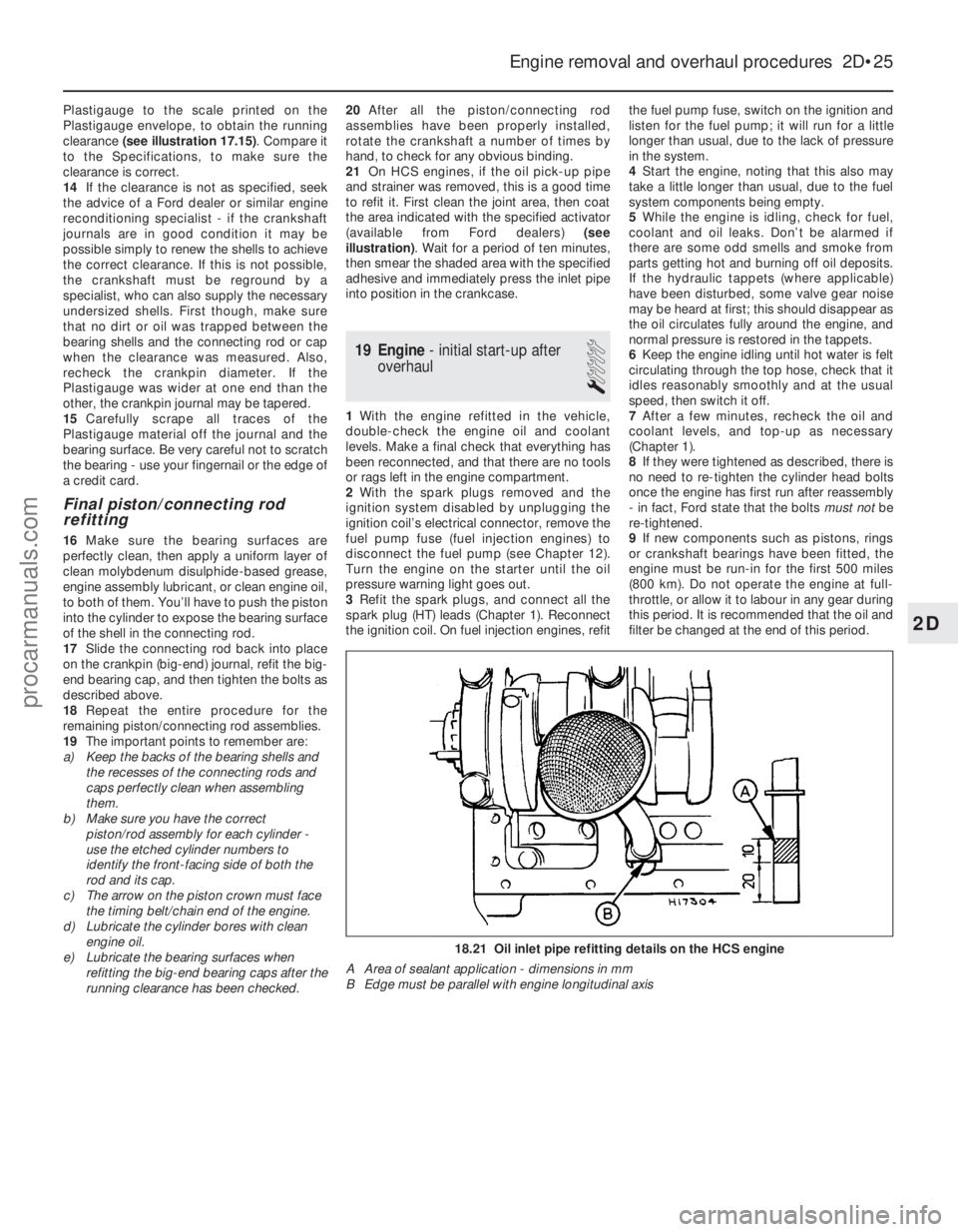
the area indicated with the specified activator
(available from Ford dealers) (see
illustration) . Wait for a period of ten minutes,
then smear the shaded area with the specified
adhesive and immediately press the inlet pipe
into position in the crankcase.
19 Engine - initial start-up after
overhaul
1
1 With the engine refitted in the vehicle,
double-check the engine oil and coolant
levels. Make a final check that everything has
been reconnected, and that there are no tools
or rags left in the engine compartment.
2 With the spark plugs removed and the
ignition system disabled by unplugging the
ignition coil’s electrical connector, remove the
fuel pump fuse (fuel injection engines) to
disconnect the fuel pump (see Chapter 12).
Turn the engine on the starter until the oil
pressure warning light goes out.
3 Refit the spark plugs, and connect all the
spark plug (HT) leads (Chapter 1). Reconnect
the ignition coil. On fuel injection engines, refit the fuel pump fuse, switch on the ignition and
listen for the fuel pump; it will run for a little
longer than usual, due to the lack of pressure
in the system.
4
Start the engine, noting that this also may
take a little longer than usual, due to the fuel
system components being empty.
5 While the engine is idling, check for fuel,
coolant and oil leaks. Don’t be alarmed if
there are some odd smells and smoke from
parts getting hot and burning off oil deposits.
If the hydraulic tappets (where applicable)
have been disturbed, some valve gear noise
may be heard at first; this should disappear as
the oil circulates fully around the engine, and
normal pressure is restored in the tappets.
6 Keep the engine idling until hot water is felt
circulating through the top hose, check that it
idles reasonably smoothly and at the usual
speed, then switch it off.
7 After a few minutes, recheck the oil and
coolant levels, and top-up as necessary
(Chapter 1).
8 If they were tightened as described, there is
no need to re-tighten the cylinder head bolts
once the engine has first run after reassembly
- in fact, Ford state that the bolts must notbe
re-tightened.
9 If new components such as pistons, rings
or crankshaft bearings have been fitted, the
engine must be run-in for the first 500 miles
(800 km). Do not operate the engine at full-
throttle, or allow it to labour in any gear during
this period. It is recommended that the oil and
filter be changed at the end of this period.
Engine removal and overhaul procedures 2D•25
18.21 Oil inlet pipe refitting details on the HCS engine
A Area of sealant application - dimensions in mm
B Edge must be parallel with engine longitudinal axis
2D
1595Ford Fiesta Remakeprocarmanuals.com
http://vnx.su
Page 161 of 296
1 General information,precautions and battery
disconnection
General information
The engine electrical system consists
mainly of the charging and starting systems.
Because of their engine-related functions,
these components are covered separately
from the body electrical devices such as the
lights, instruments, etc (which are covered in
Chapter 12). Information on the ignition
system is covered in Part B of this Chapter.
The electrical system is of the 12-volt
negative earth type. The battery is of the low maintenance or
“maintenance-free” (sealed for life) type and is
charged by the alternator, which is belt-driven
from the crankshaft pulley. The starter motor is of the pre-engaged
type incorporating an integral solenoid. On
starting, the solenoid moves the drive pinion
into engagement with the flywheel ring gear
before the starter motor is energised. Once
the engine has started, a one-way clutch
prevents the motor armature being driven by
the engine until the pinion disengages from
the flywheel.
Precautions
Further details of the various systems are
given in the relevant Sections of this Chapter.
While some repair procedures are given, the
usual course of action is to renew the
component concerned. The owner whose
interest extends beyond mere component
renewal should obtain a copy of the
“Automobile Electrical & Electronic Systems
Manual” , available from the publishers of this
manual. It is necessary to take extra care when
working on the electrical system to avoid
damage to semi-conductor devices (diodes
and transistors), and to avoid the risk of
personal injury. In addition to the precautions
given in “Safety first!” at the beginning of this
manual, observe the following when working
on the system:
Always remove rings, watches, etc before
working on the electrical system. Even with
the battery disconnected, capacitive
discharge could occur if a component’s live
terminal is earthed through a metal object.
This could cause a shock or nasty burn. Do not reverse the battery connections.
Components such as the alternator, electronic
control units, or any other components having
semi-conductor circuitry could be irreparably
damaged. If the engine is being started using jump
leads and a slave battery, connect the
batteries positive-to-positive and negative-to-
negative (see “Jump starting” ). This also
applies when connecting a battery charger.
Never disconnect the battery terminals, the
alternator, any electrical wiring or any test instruments when the engine is running.
Do not allow the engine to turn the
alternator when the alternator is not
connected. Never “test” for alternator output by
“flashing” the output lead to earth.
Never use an ohmmeter of the type
incorporating a hand-cranked generator for
circuit or continuity testing.
Always ensure that the battery negative lead
is disconnected when working on the
electrical system. Before using electric-arc welding
equipment on the car, disconnect the battery,
alternator and components such as the fuel
injection/ignition electronic control unit to
protect them from the risk of damage.
Battery disconnection
Several systems fitted to the vehicle require
battery power to be available at all times, either
to ensure that their continued operation (such as
the clock) or to maintain control unit memories
(such as that in the engine management
system’s ECU) which would be wiped if the
battery were to be disconnected. Whenever the
battery is to be disconnected therefore, first note
the following, to ensure that there are no
unforeseen consequences of this action:
a) First, on any vehicle with central locking, it is a wise precaution to remove the key
from the ignition, and to keep it with you,
so that it does not get locked in, if the
central locking should engage accidentally
when the battery is reconnected.
b) On cars equipped with an engine
management system, the system’s ECU will
lose the information stored in its memory -
referred to by Ford as the “KAM” (Keep-
Alive Memory) - when the battery is
disconnected. This includes idling and
operating values, and any fault codes
detected - in the case of the fault codes, if
it is thought likely that the system has
developed a fault for which the
corresponding code has been logged, the
vehicle must be taken to a Ford dealer for
the codes to be read, using the special
diagnostic equipment necessary for this.
Whenever the battery is disconnected, the
information relating to idle speed control
and other operating values will have to be
re-programmed into the unit’s memory.
The ECU does this by itself, but until then,
there may be surging, hesitation, erratic idle
and a generally inferior level of
performance. To allow the ECU to relearn
these values, start the engine and run it as
close to idle speed as possible until it
reaches its normal operating temperature,
then run it for approximately two minutes at
1200 rpm. Next, drive the vehicle as far as
necessary - approximately 5 miles of varied
driving conditions is usually sufficient - to
complete the relearning process.
c) If the battery is disconnected while the alarm system is armed or activated, the
alarm will remain in the same state when the battery is reconnected. The same
applies to the engine immobiliser system
(where fitted).
d) If a Ford “Keycode” audio unit is fitted,
and the unit and/or the battery is
disconnected, the unit will not function
again on reconnection until the correct
security code is entered. Details of this
procedure, which varies according to the
unit and model year, are given in the
“Ford Audio Systems Operating Guide”
supplied with the vehicle when new, with
the code itself being given in a “Radio
Passport” and/or a “Keycode Label” at
the same time. Ensure you have the
correct code before you disconnect the
battery. For obvious security reasons, the
procedure is not given in this manual. If
you do not have the code or details of the
correct procedure, but can supply proof
of ownership and a legitimate reason for
wanting this information, the vehicle’s
selling dealer may be able to help.
Devices known as “memory-savers” (or
“code-savers”) can be used to avoid some of
the above problems. Precise details vary
according to the device used. Typically, it is
plugged into the cigarette lighter, and is
connected by its own wires to a spare battery;
the vehicle’s own battery is then disconnected
from the electrical system, leaving the
“memory-saver” to pass sufficient current to
maintain audio unit security codes and ECU
memory values, and also to run permanently-
live circuits such as the clock, all the while
isolating the battery in the event of a short-
circuit occurring while work is carried out.
Warning: Some of these devices
allow a considerable amount of
current to pass, which can mean
that many of the vehicle’s
systems are still operational when the
main battery is disconnected. If a
“memory-saver” is used, ensure that the
circuit concerned is actually “dead” before
carrying out any work on it!
2 Electrical fault finding - general information
Refer to Chapter 12.
3 Battery -testing and charging
1
Standard and low maintenance
battery - testing
1If the vehicle covers a small annual mileage,
it is worthwhile checking the specific gravity
of the electrolyte every three months to
determine the state of charge of the battery.
Use a hydrometer to make the check and
compare the results with the following table.
5A•2 Starting and charging systems
1595Ford Fiesta Remakeprocarmanuals.com
http://vnx.su
Page 236 of 296
 . . . . . . . . . . . . . . . . . . . . . . . . . . . . . . . . . . . .\
. . . . . H4, 60/55
Sidelight (front) . . . . . . . . . . . . . . . . . . . . . . . . . . .")
BulbsWattage
Headlight (halogen) . . . . . . . . . . . . . . . . . . . . . . . . . . . . . . . . . . . .\
. . . . . H4, 60/55
Sidelight (front) . . . . . . . . . . . . . . . . . . . . . . . . . . . . . . . . . . . .\
. . . . . . . . 5
Direction indicators (main) . . . . . . . . . . . . . . . . . . . . . . . . . . . . . . . . . . . 21
Side direction indicator repeaters . . . . . . . . . . . . . . . . . . . . . . . . . . . . . . 5
Auxiliary driving and foglights (S and XR2i) . . . . . . . . . . . . . . . . . . . . . . H3, 55
Stop/tail light . . . . . . . . . . . . . . . . . . . . . . . . . . . . . . . . . . . .\
. . . . . . . . . . 21/5
Rear foglight . . . . . . . . . . . . . . . . . . . . . . . . . . . . . . . . . . . .\
. . . . . . . . . . 21
Reversing light . . . . . . . . . . . . . . . . . . . . . . . . . . . . . . . . . . . .\
. . . . . . . . 21
Number plate light . . . . . . . . . . . . . . . . . . . . . . . . . . . . . . . . . . . .\
. . . . . 10
Interior light . . . . . . . . . . . . . . . . . . . . . . . . . . . . . . . . . . . .\
. . . . . . . . . . . 10
Luggage compartment light . . . . . . . . . . . . . . . . . . . . . . . . . . . . . . . . . . 5
Instrument warning lights . . . . . . . . . . . . . . . . . . . . . . . . . . . . . . . . . . . .\
1.3 or 2.6
Panel illumination . . . . . . . . . . . . . . . . . . . . . . . . . . . . . . . . . . . .\
. . . . . . 1.3 or 2.6
Cigarette lighter illumination . . . . . . . . . . . . . . . . . . . . . . . . . . . . . . . . . . 1.4
Automatic transmission selector illumination . . . . . . . . . . . . . . . . . . . . . 2
Lubricants
Grease for windscreen wiper linkage and pivots . . . . . . . . . . . . . . . . . . To Ford specification SAM-1C-911-A
Torque wrench settingsNm lbf ft
Wiper motor to bracket . . . . . . . . . . . . . . . . . . . . . . . . . . . . . . . . . . . .\
. . 8 to 9 6 to 7
Wiper motor bracket to bulkhead/tailgate . . . . . . . . . . . . . . . . . . . . . . . 6 to 8 4 to 6
Windscreen wiper crank to driving shaft nut . . . . . . . . . . . . . . . . . . . . . 22 to 24 16 to 18
Windscreen/tailgate wiper arm retaining nut . . . . . . . . . . . . . . . . . . . . . 17 to 18 12 to 13
Windscreen wiper pivot shaft nut . . . . . . . . . . . . . . . . . . . . . . . . . . . . . . 9 to 12 7 to 9
Windscreen/tailgate washer reservoir securing bolts . . . . . . . . . . . . . . . 2.5 to 3.5 2 to 3
Headlight retaining bolt . . . . . . . . . . . . . . . . . . . . . . . . . . . . . . . . . . . .\
. 5.4 to 7.0 4 to 5
Tail light securing nuts . . . . . . . . . . . . . . . . . . . . . . . . . . . . . . . . . . . .\
. . 1.5 to 2.5 1 to 2
Auxiliary light retaining nut (S models) . . . . . . . . . . . . . . . . . . . . . . . . . . 6.8 to 9.2 5 to 7
Horn bracket retaining bolt . . . . . . . . . . . . . . . . . . . . . . . . . . . . . . . . . . . 24 to 33 18 to 24
Starter inhibitor switch . . . . . . . . . . . . . . . . . . . . . . . . . . . . . . . . . . . .\
. . 9 to 14 7 to 10
Body electrical systems 12•3
12
1595Ford Fiesta Remake
1 General information and
precautions
General information
The electrical system is of 12-volt negative
earth type. Power for the lights and all
electrical accessories is supplied by a
lead/acid battery, which is charged by the
engine-driven alternator.
This Chapter covers repair and service
procedures for the various electrical
components not associated with the engine.
Information on the battery, ignition system,
alternator, and starter motor can be found in
Chapter 5A and B.
All models from 1994 onwards are fitted
with a driver’s air bag, which is designed to
prevent serious chest and head injuries to the
driver during an accident. A similar bag for the
front seat passenger is also available. The
combined sensor and electronics for the air
bag is located next to the steering column
inside the vehicle, and contains a back-up
capacitor, crash sensor, decelerometer,
safety sensor, integrated circuit and
microprocessor. The air bag is inflated by a
gas generator, which forces the bag out of the module cover in the centre of the steering
wheel. A “clock spring” ensures that a good
electrical connection is maintained with the air
bag at all times - as the steering wheel is
turned in each direction, the spring winds and
unwinds.
An anti-theft alarm system is available on
later models, and is triggered if the vehicle is
broken into through the doors, bonnet, or
tailgate. The alarm will also be triggered if the
ignition or audio equipment is tampered with.
Additionally, from the 1994 model year
onwards, a Passive Anti-Theft System (PATS)
is fitted. This system, (which works
independently of the standard alarm) prevents
the engine from being started unless a
specific code, programmed into the ignition
key, is recognised by the PATS transceiver.
Precautions
Warning: Before carrying out
any work on the electrical
system, read through the
precautions given in “Safety
first!” at the beginning of this manual and
in Chapter 5A, Section 1.
Caution: Prior to working on any
component in the electrical system, the
battery negative lead should first be
disconnected, to prevent the possibility of electrical short-circuits and/or fires. If a
radio/cassette player with anti-theft
security code is fitted, refer to the
information given in the reference sections
of this manual before disconnecting the
battery.
2 Electrical fault-finding
-
general information
2
Note: Refer to the precautions given in
“Safety first!” and in Section 1 of this Chapter
before starting work. The following tests relate
to testing of the main electrical circuits, and
should not be used to test delicate electronic
circuits (such as engine management
systems), particularly where an electronic
control unit is used. Also refer to the
precautions given in Chapter 5A, Section 1.
General
1 A typical electrical circuit consists of an
electrical component, any switches, relays,
motors, fuses, fusible links or circuit breakers
related to that component, and the wiring and
connectors which link the component to both
the battery and the chassis. To help to
pinpoint a problem in an electrical circuit,
procarmanuals.com
http://vnx.su
Page 250 of 296
27 Anti-theft systems-
general information
Anti-theft alarm system
1 This system provides an added form of
vehicle security. When the system is
activated, the alarm will sound if the vehicle is
broken into through any one of the doors, the
bonnet, or tailgate. The alarm will also be
triggered if the ignition system is turned on or
the radio/cassette disconnected whilst the
system is activated.
2 This system is activated/de-activated
whenever one of the front doors is
locked/unlocked by the key. The system
operates on all doors, the bonnet and tailgate
whenever each door is individually locked (or,
in the case of central locking, when the central
locking is engaged). In addition, the
ignition/starting system is also immobilised
when the system is activated.
3 A further security feature included is that
even though the battery may be disconnected
whilst the system is activated, the alarm
activation continues as soon as the battery is
reconnected. Because of this feature, it is
important to ensure that the system is de-
activated before disconnecting the battery at
any time, such as when working on the
vehicle.
4 The system incorporates a diagnostic mode
to enable Ford technicians to quickly identify
any faults in the system. In the event of a
system malfunction, any testing or
component removal and refitting should be
entrusted to a Ford dealer.
Passive Anti-Theft System
(PATS)
5 From 1994 model year onwards, a Passive
Anti-Theft System (PATS) is fitted. This
system, (which works independently of the
standard alarm system) is a vehicle
immobiliser which prevents the engine from
being started unless a specific code,
programmed into the ignition key, is
recognised by the PATS transceiver.
6 The PATS transceiver, fitted around the
ignition switch, decodes a signal from the
ignition key as the key is turned from position
“O” to position “II”. If the coded signal
matches that stored in the memory of the
PATS module, the engine will start. If the
signal is not recognised, the engine will crank
on the starter but will not fire.
28 Air bag (driver’s side) -
removal and refitting
4
Warning: Handle the air bag
with extreme care as a
precaution against personal
injury, and always hold it with the cover facing away from your body. If in
doubt concerning any proposed work
involving the air bag or its control circuitry,
consult a Ford dealer or other qualified
specialist.
Removal
1
Disconnect the battery negative (earth) lead
(refer to Chapter 5A, Section 1). Warning: Before proceeding,
wait a minimum of 15 minutes,
as a precaution against
accidental firing of the air bag.
This period ensures that any stored energy
in the back-up capacitor is dissipated.
2 Undo the screws, and remove the steering
column lower shroud.
3 Undo the two external screws and the two
internal screws and remove the steering
column upper shroud.
4 Turn the steering wheel as necessary so
that one of the air bag module retaining bolts
becomes accessible from the rear of the
steering wheel. Undo the bolt, then turn the
steering wheel again until the second bolt is
accessible. Undo this bolt also.
5 Withdraw the air bag module from the
steering wheel far enough to access the
wiring multi-plug. Some force may be needed
to free the module from the additional steering
wheel spoke retainers.
6 Disconnect the multi-plug from the rear of
the module, and remove the module from the
vehicle. Warning: Position the air bag
module in a safe place, with the
mechanism facing downwards
as a precaution against
accidental operation.
Warning: Do not attempt to
open or repair the air bag unit,
or apply any electrical current to
it. Do not use any air bag which
is visibly damaged or which has been
tampered with.
Refitting
7 Refitting is a reversal of the removal
procedure.
29 Air bag (passenger’s side) -
removal and refitting
4
Warning: Handle the air bag
with extreme care as a
precaution against personal
injury, and always hold it with
the cover facing away from your body. If in
doubt concerning any proposed work
involving the air bag or its control circuitry,
consult a Ford dealer or other qualified
specialist.
Removal
1 Disconnect the battery negative (earth) lead
(refer to Chapter 5A, Section 1). Warning: Before proceeding,
wait a minimum of 15 minutes,
as a precaution against
accidental firing of the air bag.
This period ensures that any stored energy
in the back-up capacitor is dissipated.
2 Remove the facia as described in Chap-
ter 11.
3 Undo the air bag module retaining nuts and
remove the unit from the facia. Warning: Position the air bag
module in a safe place, with the
mechanism facing downwards
as a precaution against
accidental operation.
Warning: Do not attempt to
open or repair the air bag unit,
or apply any electrical current to
it. Do not use any air bag which
is visibly damaged or which has been
tampered with.
Refitting
4 Refitting is a reversal of the removal
procedure.
30 Air bag control module -
removal and refitting
4
Removal
1 Disconnect the battery negative (earth) lead
(refer to Chapter 5A, Section 1). Warning: Before proceeding,
wait a minimum of 15 minutes,
as a precaution against
accidental firing of the air bag
unit. This period ensures that any stored
energy in the back-up capacitor is
dissipated.
2 Remove the module access cover from the
rear of the glovebox.
3 Press the module wiring multi-plug locking
tag upwards then pivot the retaining strap
over and disconnect the multi-plug.
4 Remove the facia as described in Chap-
ter 11.
5 Undo the three retaining bolts and remove
the module from its location.
Refitting
6 Refitting is a reversal of the removal
procedure.
31 Air bag clock spring -
removal and refitting
4
Removal
1 Remove the steering wheel as described in
Chapter 10.
2 Undo the three retaining screws, and
remove the clock spring from the steering
wheel. As the unit is withdrawn, note which
aperture in the steering wheel the air bag
Body electrical systems 12•17
12
1595Ford Fiesta Remakeprocarmanuals.com
http://vnx.su
Page 293 of 296
1595 Ford Fiesta Remake
IndexREF•27
REF
Note: References throughout this index relate to Chapter•page number
A
Accelerator cable -4A•4, 4B•4, 4C•4, 4D•3
Accelerator pedal - 4A•4, 4B•4, 4C•4, 4D•3
Accelerator pump - 4A•8
Acknowledgements - 0•4
Aerial - 12•16
Air bags - 0•5, 12•17
Air cleaner - 1•22, 1•23, 4A•3, 4B•4, 4C•3,
4D•3, 4E•5
Air temperature control system - 1•23,
4B•8, 4C•7, 4D•6
Alarm system - 12•17, REF• 5
Alternator - 5A•4
Anti-lock braking system (ABS) - 9•11,
9•14, 9•16
Anti-roll bar - 10•7, 10•11
Anti-theft alarm system - 12•17, REF•5
Antifreeze - 0•12, 0•17, 1•21, 1•22, 3•2
Asbestos - 0•5
ATF - 0•17, 1•18, 1•24
Automatic choke - 4A•16, 4A•17
Automatic transmission -2A•10, 2B•13,
2C•15, 2D•6, 2D•8, 2D•10, 7B•1 et seq,
12 •6, 12 •8
Automatic transmission fault finding - REF• 18
Automatic transmission fluid - 0•17, 1•18,
1•24
Auxiliary lights - 12•7, 12•10
Axle - 10•10
B
Backfire - REF•16
Backrest - 11•17
Ballast resistor - 4B•9
Balljoint - 10•17
Battery - 0•5, 0•14, 5A•2, 5A•3
Battery fault - REF•20
Big-end bearings - 2D•21, 2D•24
Bleeding braking system - 9•10, 9•11
Bleeding power steering - 10•17
Body electrical systems -1•18, 12 •1et seq,
REF• 11
Body electrical system fault finding - 5A•2,
12 •3, REF •20
Bodywork and fittings -1•18, 11 •1et seq,
REF• 13
Bonnet - 1•18, 11•4,11•5
Boot - 1•16
Boots - 8•3, 8•4, 10 •15
Brake fluid - 0•13, 0•17, 1•26, 12 •6
Braking system -1•17, 9•1 et seq, 12•6,
REF• 10, REF•11, REF• 12
Braking system fault finding - REF•18 Bulbs -
0•16, 12 •7,12•8
Bumpers - 11•7, 11•8
Burning - 0•5
Buying spare parts - REF•5
C
Cables -4A•4, 4B•4, 4C•4, 4D•3, 6•1, 7B•2,
9•12, 9•13, 12 •12
Calipers - 9•3
Camshaft - 2B•6, 2B•7, 2C•7, 2C•8, 2D•16
Camshaft position sensor - 4D•6
Carburettor - 4A•7, 4A•8, 4A•9, 4A•11,
4A•13, 4A•14, 4A•15, 4A•17, 4A•18
Carpets - 11•2
Cassette player - 12•15, REF •5
Catalytic converter - 4E•2, 4E•5
Centre console - 11•20, 12 •5
Charcoal canister - 4E•6
Charging system - 5A•3
Choke - 4A•4, 4A•16, 4A•17
Cigarette lighter - 12•9, 12 •12
Clock - 12•8, 12•12
Clutch -1•18, 6•1 et seq
Clutch fault finding - REF•17
Coil - 5B•4
Compression test - 2A•3, 2B•3, 2C•3
Connecting rods - 2D•17, 2D•24, 2D•25
Console - 11•20, 12•5
Contents - 0•2
Conversion factors - REF•6
Coolant - 0•12, 0•17, 1•21, 1•22, 3•2
Coolant pump - 3•7
Coolant temperature sensor - 4B•8, 4C•7,
4D•6
Cooling ,heating and ventilation systems -
3•1 et seq
Cooling system fault finding - REF•16
Courtesy light - 12•6, 12•9
Crankcase - 2D•19
Crankcase ventilation system - 1•24
Crankshaft - 2A•6, 2A•9, 2B•4, 2B•6,
2B•12, 2C•4, 2C•7, 2C•14, 2D•18,
2D•22, 2D•24
Crankshaft position sensor - 4B•8, 4C•7,
4D•6, 5B•5
Crossmember - 10•7
Crushing - 0•5
Cushion - 11•17
CV joint - 1•16, 8•3, 8•4
CVH and PTE engine in-car repair
procedures -2B•1 et seq
Cylinder block - 2D•19
Cylinder head - 2A•4, 2A•5, 2B•4, 2B•9,
2C•3, 2C•10, 2D•12, 2D•14, 2D•15
D
Dents in bodywork - 11•2
Depressurising fuel system - 4B•3, 4C•3,
4D•2
Differential - 7A•3, 7B•3
Dimensions - REF•1
Direction indicators - 12•7, 12•9, 12•10
Discs - 9•4
Distributor - 1•20, 5B•5, 5B•6, 5B•7
Doors - 1•18, 11• 6,11•9, 11 •10,,11 •11,
11 •13, 11•14, 11•15, REF •11
Drip rail moulding - 11•5
Drivebelt - 1•11
Driveplate - 2B•14, 2C•16
Driveshafts -1•16, 8•1 et seq,REF•12
Driveshafts fault finding - REF•19
Drivetrain - 1•18
Drums - 9•4
E
Earth fault - 12•4
EEC IV engine management module - 4C•6
Electric shock - 0•5
Electric windows - 11•14, 12 •7, 12•15,
REF•20
Emblems - 11•5
Emission control system - 1•24, 4E•1
Engine fault finding - REF•15, REF•16,
REF •18
Engine oil - 0•12, 0•17, 1•9
Engine removal and overhaul procedures -
2D•1 et seq
Environmental considerations - REF•4
Evaporative emission control systems - 1•24, 4E•2, 4E•5
Exhaust and emission control systems -
4E•1 et seq
Exhaust emission checks - REF•13
Exhaust manifold - 4E•3
Exhaust system - 1•16, 4E•1, 4E•2, REF •5,
REF •12
Exhaust system fault - REF•17
Expansion tank - 3•6
F
Facia - 11•20, 12 •5
Fan - 3•4
Fast-idle speed adjustment - 4A•13, 4A•15,
4A•9, 4A•7
Fault finding - REF•14et seq
Fault finding - automatic transmission -
REF •18
Fault finding - braking system - REF•18
procarmanuals.com
http://vnx.su