1989 FORD FIESTA brake sensor
[x] Cancel search: brake sensorPage 6 of 296
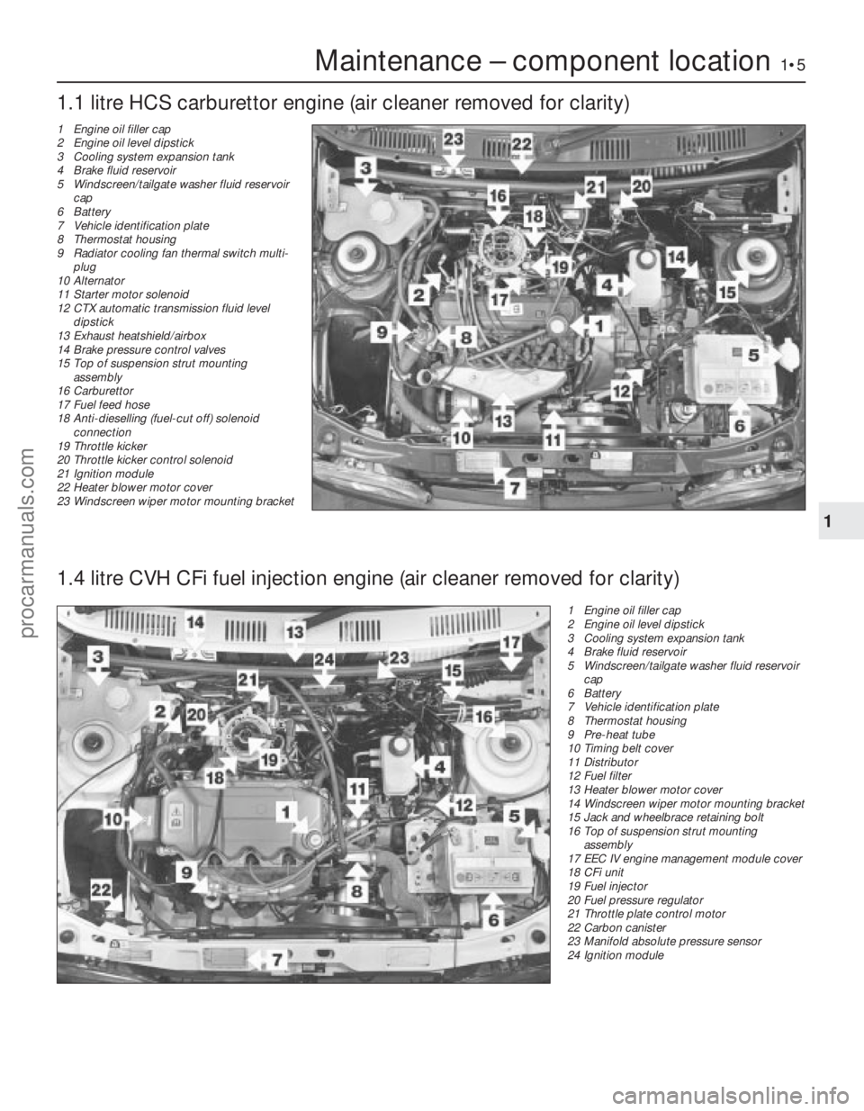
Maintenance – component location1•5
1 Engine oil filler cap
2 Engine oil level dipstick
3 Cooling system expansion tank
4 Brake fluid reservoir
5 Windscreen/tailgate washer fluid reservoircap
6 Battery
7 Vehicle identification plate
8 Thermostat housing
9 Pre-heat tube
10 Timing belt cover
11 Distributor
12 Fuel filter
13 Heater blower motor cover
14 Windscreen wiper motor mounting bracket
15 Jack and wheelbrace retaining bolt
16 Top of suspension strut mounting
assembly
17 EEC IV engine management module cover
18 CFi unit
19 Fuel injector
20 Fuel pressure regulator
21 Throttle plate control motor
22 Carbon canister
23 Manifold absolute pressure sensor
24 Ignition module
1.1 litre HCS carburettor engine (air cleaner removed for clarity)
1
1595Ford Fiesta Remake
1.4 litre CVH CFi fuel injection engine (air cleaner removed for clarity)
1 Engine oil filler cap
2 Engine oil level dipstick
3 Cooling system expansion tank
4 Brake fluid reservoir
5 Windscreen/tailgate washer fluid reservoir
cap
6 Battery
7 Vehicle identification plate
8 Thermostat housing
9 Radiator cooling fan thermal switch multi- plug
10 Alternator
11 Starter motor solenoid
12 CTX automatic transmission fluid level
dipstick
13 Exhaust heatshield/airbox
14 Brake pressure control valves
15 Top of suspension strut mounting
assembly
16 Carburettor
17 Fuel feed hose
18 Anti-dieselling (fuel-cut off) solenoid
connection
19 Throttle kicker
20 Throttle kicker control solenoid
21 Ignition module
22 Heater blower motor cover
23 Windscreen wiper motor mounting bracket
procarmanuals.com
http://vnx.su
Page 7 of 296
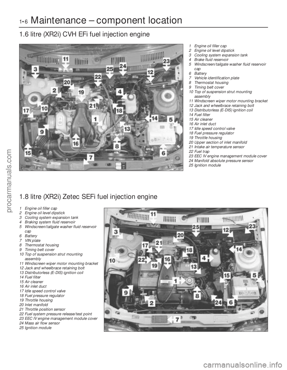
1•6Maintenance – component location
1.6 litre (XR2i) CVH EFi fuel injection engine
1595Ford Fiesta Remake1 Engine oil filler cap
2 Engine oil level dipstick
3 Cooling system expansion tank
4 Brake fluid reservoir
5 Windscreen/tailgate washer fluid reservoir
cap
6 Battery
7 Vehicle identification plate
8 Thermostat housing
9 Timing belt cover
10 Top of suspension strut mounting
assembly
11 Windscreen wiper motor mounting bracket
12 Jack and wheelbrace retaining bolt
13 Distributorless (E-DIS) ignition coil
14 Fuel filter
15 Air cleaner
16 Air inlet duct
17 Idle speed control valve
18 Fuel pressure regulator
19 Throttle housing
20 Upper section of inlet manifold
21 Intake air temperature sensor
22 Fuel trap
23 EEC IV engine management module cover
24 Manifold absolute pressure sensor
25 Ignition module
1.8 litre (XR2i) Zetec SEFi fuel injection engine
1 Engine oil filler cap
2 Engine oil level dipstick
3 Cooling system expansion tank
4 Braking system fluid reservoir
5 Windscreen/tailgate washer fluid reservoir
cap
6 Battery
7 VIN plate
8 Thermostat housing
9 Timing belt cover
10 Top of suspension strut mounting
assembly
11 Windscreen wiper motor mounting bracket
12 Jack and wheelbrace retaining bolt
13 Distributorless (E-DIS) ignition coil
14 Fuel filter
15 Air cleaner
16 Air inlet duct
17 Idle speed control valve
18 Fuel pressure regulator
19 Throttle housing
20 Inlet manifold
21 Throttle position sensor
22 Fuel system pressure release/test point
23 EEC IV engine management module cover
24 Mass air flow sensor
25 Ignition module
procarmanuals.com
http://vnx.su
Page 8 of 296
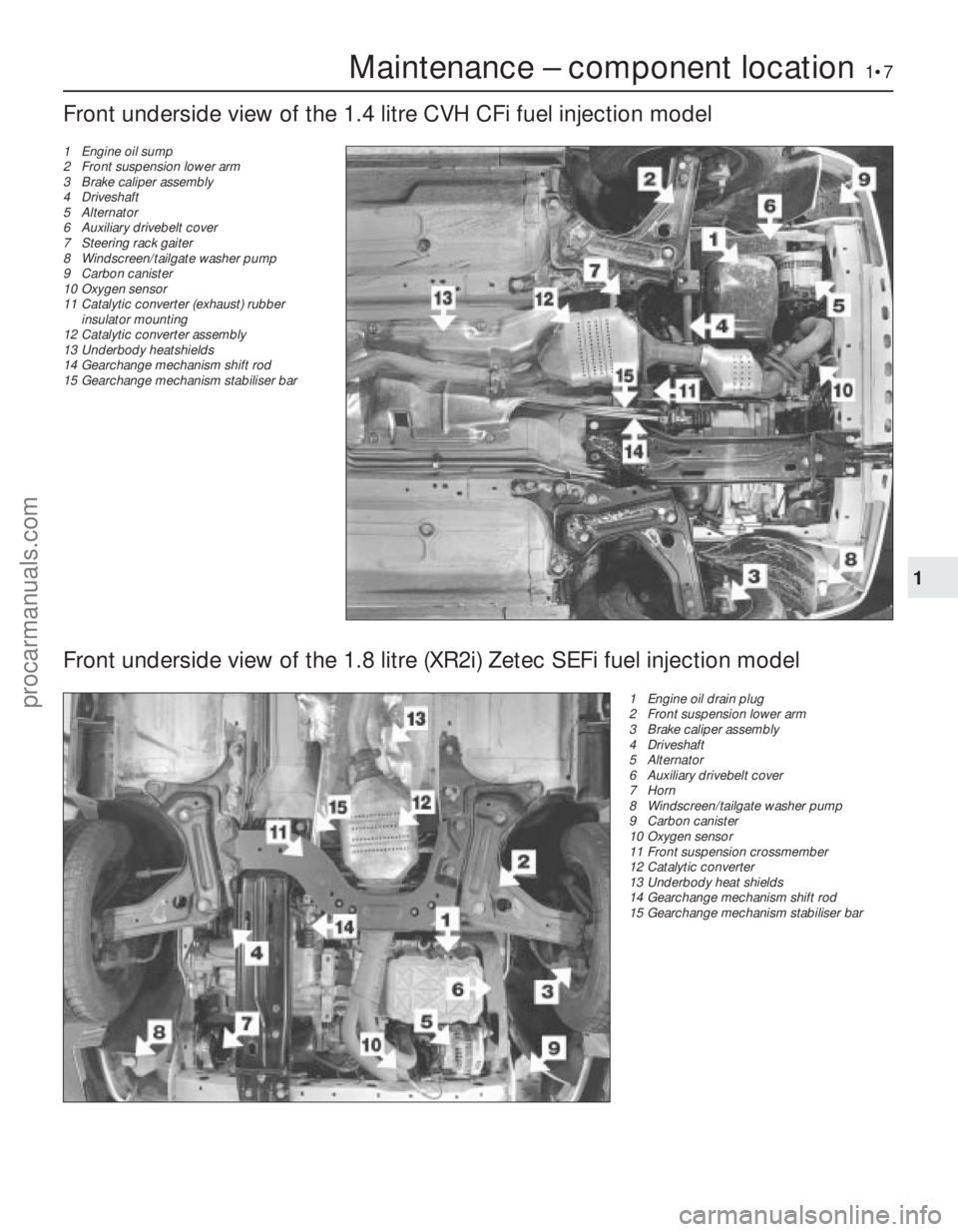
Maintenance – component location1•7
1
1595Ford Fiesta Remake
Front underside view of the 1.4 litre CVH CFi fuel injection model
1 Engine oil sump
2 Front suspension lower arm
3 Brake caliper assembly
4 Driveshaft
5 Alternator
6 Auxiliary drivebelt cover
7 Steering rack gaiter
8 Windscreen/tailgate washer pump
9 Carbon canister
10 Oxygen sensor
11 Catalytic converter (exhaust) rubber
insulator mounting
12 Catalytic converter assembly
13 Underbody heatshields
14 Gearchange mechanism shift rod
15 Gearchange mechanism stabiliser bar
Front underside view of the 1.8 litre (XR2i) Zetec SEFi fuel injection model
1 Engine oil drain plug
2 Front suspension lower arm
3 Brake caliper assembly
4 Driveshaft
5 Alternator
6 Auxiliary drivebelt cover
7 Horn
8 Windscreen/tailgate washer pump
9 Carbon canister
10 Oxygen sensor
11 Front suspension crossmember
12 Catalytic converter
13 Underbody heat shields
14 Gearchange mechanism shift rod
15 Gearchange mechanism stabiliser bar
procarmanuals.com
http://vnx.su
Page 48 of 296
23Refer to the procedure in Section 9 when
refitting the camshaft sprocket.
24 Refit and tension the timing belt as
described in Section 8.
25 Lubricate the hydraulic tappets with
hypoid oil before refitting them into their
original locations in the cylinder head.
26 Lubricate and refit the rocker arms and
guides in their original sequence, use new
nuts and tighten them to the specified torque
setting. It is essential, before each rocker arm
is installed and its nut tightened, that the
respective cam follower is positioned at its
lowest point (in contact with the cam base
circle). Turn the cam (using the crankshaft
pulley bolt) as necessary to achieve this.
27 Refit the rocker cover as described in
Section 4.
28 Refit the remaining components with
reference to the relevant Sections in this
Chapter or elsewhere in the manual.
29 On completion, reconnect the battery
negative lead.
12 Cylinder head -
removal and refitting
4
Removal
Note: The following procedure describes
removal and refitting of the cylinder head
complete with inlet and exhaust manifolds. If
wished, the manifolds may be removed first,
as described in the relevant Part of Chapter 4,
and the cylinder head then removed on its
own.
1 On fuel-injected engines, depressurise the
fuel system as described in Chapter 4B or 4C.
2 Disconnect the battery negative (earth) lead
(refer to Chapter 5A, Section 1).
3 Refer to Chapter 1 and drain the cooling
system. 4
Remove the rocker cover as described in
Section 4.
5 Disconnect the accelerator and choke
cables as applicable (refer to the relevant Part
of Chapter 4).
6 Loosen off the retaining clips and
disconnect the upper coolant hose, the
expansion tank hose and the heater hose
from the thermostat housing. Also disconnect
the heater hose from the inlet manifold.
7 On CFi models, disconnect the heated
coolant hose from the injector unit.
8 On EFi and SEFi models, disconnect the
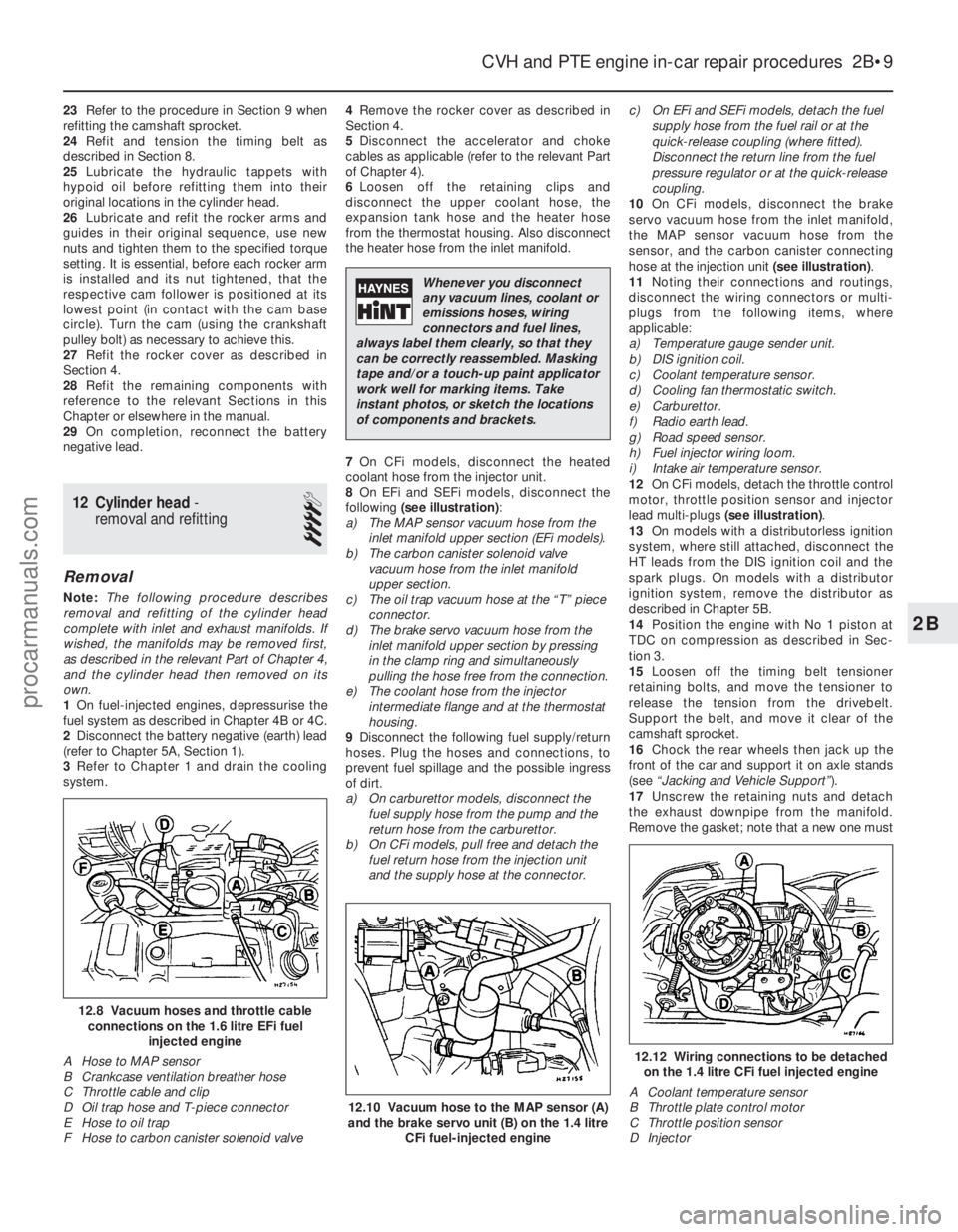
following (see illustration) :
a) The MAP sensor vacuum hose from the inlet manifold upper section (EFi models).
b) The carbon canister solenoid valve
vacuum hose from the inlet manifold
upper section.
c) The oil trap vacuum hose at the “T” piece
connector.
d) The brake servo vacuum hose from the
inlet manifold upper section by pressing
in the clamp ring and simultaneously
pulling the hose free from the connection.
e) The coolant hose from the injector
intermediate flange and at the thermostat
housing.
9 Disconnect the following fuel supply/return
hoses. Plug the hoses and connections, to
prevent fuel spillage and the possible ingress
of dirt.
a) On carburettor models, disconnect the fuel supply hose from the pump and the
return hose from the carburettor.
b) On CFi models, pull free and detach the
fuel return hose from the injection unit
and the supply hose at the connector. c) On EFi and SEFi models, detach the fuel
supply hose from the fuel rail or at the
quick-release coupling (where fitted).
Disconnect the return line from the fuel
pressure regulator or at the quick-release
coupling.
10 On CFi models, disconnect the brake
servo vacuum hose from the inlet manifold,
the MAP sensor vacuum hose from the
sensor, and the carbon canister connecting
hose at the injection unit (see illustration).
11 Noting their connections and routings,
disconnect the wiring connectors or multi-
plugs from the following items, where
applicable:
a) Temperature gauge sender unit.
b) DIS ignition coil.
c) Coolant temperature sensor.
d) Cooling fan thermostatic switch.
e) Carburettor.
f) Radio earth lead.
g) Road speed sensor.
h) Fuel injector wiring loom.
i) Intake air temperature sensor.
12 On CFi models, detach the throttle control
motor, throttle position sensor and injector
lead multi-plugs (see illustration) .
13 On models with a distributorless ignition
system, where still attached, disconnect the
HT leads from the DIS ignition coil and the
spark plugs. On models with a distributor
ignition system, remove the distributor as
described in Chapter 5B.
14 Position the engine with No 1 piston at
TDC on compression as described in Sec-
tion 3.
15 Loosen off the timing belt tensioner
retaining bolts, and move the tensioner to
release the tension from the drivebelt.
Support the belt, and move it clear of the
camshaft sprocket.
16 Chock the rear wheels then jack up the
front of the car and support it on axle stands
(see “Jacking and Vehicle Support” ).
17 Unscrew the retaining nuts and detach
the exhaust downpipe from the manifold.
Remove the gasket; note that a new one must
CVH and PTE engine in-car repair procedures 2B•9
12.12 Wiring connections to be detached on the 1.4 litre CFi fuel injected engine
A Coolant temperature sensor
B Throttle plate control motor
C Throttle position sensor
D Injector
12.10 Vacuum hose to the MAP sensor (A)
and the brake servo unit (B) on the 1.4 litre
CFi fuel-injected engine
12.8 Vacuum hoses and throttle cableconnections on the 1.6 litre EFi fuel injected engine
A Hose to MAP sensor
B Crankcase ventilation breather hose
C Throttle cable and clip
D Oil trap hose and T-piece connector
E Hose to oil trap
F Hose to carbon canister solenoid valve
2B
1595Ford Fiesta Remake
Whenever you disconnect
any vacuum lines, coolant or
emissions hoses, wiring
connectors and fuel lines,
always label them clearly, so that they
can be correctly reassembled. Masking
tape and/or a touch-up paint applicator
work well for marking items. Take
instant photos, or sketch the locations
of components and brackets.
procarmanuals.com
http://vnx.su
Page 76 of 296
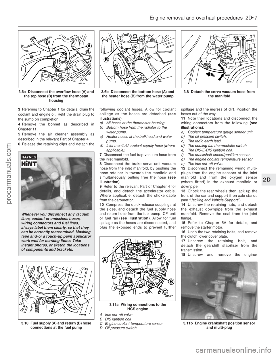
3Referring to Chapter 1 for details, drain the
coolant and engine oil. Refit the drain plug to
the sump on completion.
4 Remove the bonnet as described in
Chapter 11.
5 Remove the air cleaner assembly as
described in the relevant Part of Chapter 4.
6 Release the retaining clips and detach the following coolant hoses. Allow for coolant
spillage as the hoses are detached
(see
illustrations) :
a) All hoses at the thermostat housing.
b) Bottom hose from the radiator to the
water pump.
c) Heater hoses at the bulkhead and water
pump.
d) Inlet manifold coolant supply hose (where
applicable).
7 Disconnect the fuel trap vacuum hose from
the inlet manifold.
8 Disconnect the brake servo unit vacuum
hose from the inlet manifold, by pushing the
hose retainer in towards the manifold and
simultaneously pulling free the hose (see
illustration) .
9 Refer to the relevant Part of Chapter 4 for
details, and detach the accelerator cable.
Where applicable, detach the choke cable
from the carburettor.
10 Compress the quick-release couplings at
the sides, and detach the fuel supply hose
and return hose from the fuel pump, CFi unit
or fuel rail (see illustration) . Allow for fuel
spillage as the hoses are disconnected, and
plug the exposed ends to prevent further spillage and the ingress of dirt. Position the
hoses out of the way.
11
Note their locations and disconnect the
wiring connectors from the following (see
illustrations) :
a) Coolant temperature gauge sender unit.
b) The oil pressure switch.
c) The radio earth lead.
d) The cooling fan thermostatic switch.
e) The DIS/E-DIS ignition coil.
f) The crankshaft speed/position sensor.
g) The engine coolant temperature sensor.
h) The idle cut-off valve.
12 Disconnect the remaining wiring multi-
plugs from the engine sensors at the inlet
manifold and from the oxygen sensor
(where fitted) in the exhaust manifold or
downpipe.
13 Chock the rear wheels then jack up the
front of the car and support it on axle stands
(see “Jacking and Vehicle Support” ).
14 Unscrew the retaining nuts, and detach
the exhaust downpipe from the exhaust
manifold. Remove the seal from the joint
flange.
15 Refer to Chapter 5A for details, and
remove the starter motor.
16 Undo the two retaining bolts, and remove
the clutch lower cover plate.
17 Unscrew the retaining bolt, and
detach the gearshift stabiliser from the
transmission.
18 Unscrew and remove the engine/
Engine removal and overhaul procedures 2D•7
3.8 Detach the servo vacuum hose from
the manifold3.6b Disconnect the bottom hose (A) andthe heater hose (B) from the water pump3.6a Disconnect the overflow hose (A) and the top hose (B) from the thermostat housing
3.11b Engine crankshaft position sensorand multi-plug
3.11a Wiring connections to the HCS engine
A Idle cut-off valve
B DIS ignition coil
C Engine coolant temperature sensor
D Oil pressure switch
3.10 Fuel supply (A) and return (B) hose connections at the fuel pump
2D
1595Ford Fiesta Remake
Whenever you disconnect any vacuum
lines, coolant or emissions hoses,
wiring connectors and fuel lines,
always label them clearly, so that they
can be correctly reassembled. Masking
tape and/or a touch-up paint applicator
work well for marking items. Take
instant photos, or sketch the locations
of components and brackets.
procarmanuals.com
http://vnx.su
Page 78 of 296
7Refer to the relevant Part of Chapter 4 for
details, and disconnect the accelerator cable
from the throttle linkage and support/adjuster
bracket. Where applicable, also disconnect
the choke cable. Position the cable(s) out of
the way.
8 On carburettor models, disconnect the fuel
supply hose from the fuel pump, and the
return hose from the carburettor.
9 On CFi models, detach the fuel hose at the
injector/pressure regulator unit, and the return
line, by compressing the couplings whilst
pulling the hoses free from their connections.
On EFi and SEFi models, unscrew the union
nut to detach the fuel line from the fuel rail;
release the retaining clip to detach the return
pipe from the pressure regulator. Plug the
exposed ends of the hoses and connections,
to prevent fuel spillage and the ingress of dirt.
Position the hoses out of the way.
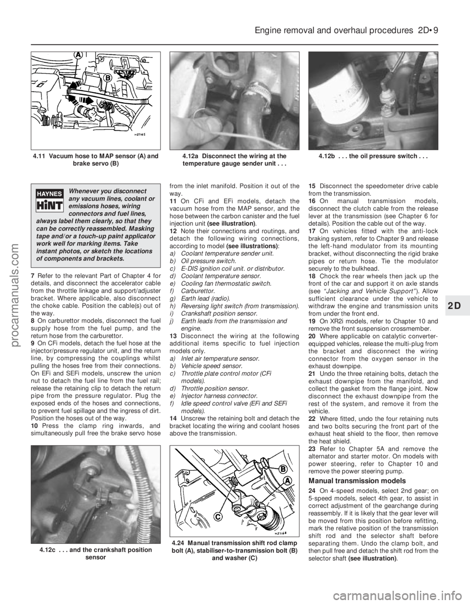
10 Press the clamp ring inwards, and
simultaneously pull free the brake servo hose from the inlet manifold. Position it out of the
way.
11
On CFi and EFi models, detach the
vacuum hose from the MAP sensor, and the
hose between the carbon canister and the fuel
injection unit (see illustration) .
12 Note their connections and routings, and
detach the following wiring connections,
according to model (see illustrations):
a) Coolant temperature sender unit.
b) Oil pressure switch.
c) E-DIS ignition coil unit. or distributor.
d) Coolant temperature sensor.
e) Cooling fan thermostatic switch.
f) Carburettor.
g) Earth lead (radio).
h) Reversing light switch (from transmission).
i) Crankshaft position sensor.
j) Earth leads from the transmission and engine.
13 Disconnect the wiring at the following
additional items specific to fuel injection
models only.
a) Inlet air temperature sensor.
b) Vehicle speed sensor.
c) Throttle plate control motor (CFi models).
d) Throttle position sensor.
e) Injector harness connector.
f) Idle speed control valve (EFi and SEFi models).
14 Unscrew the retaining bolt and detach the
bracket locating the wiring and coolant hoses
above the transmission. 15
Disconnect the speedometer drive cable
from the transmission.
16 On manual transmission models,
disconnect the clutch cable from the release
lever at the transmission (see Chapter 6 for
details). Position the cable out of the way.
17 On vehicles fitted with the anti-lock
braking system, refer to Chapter 9 and release
the left-hand modulator from its mounting
bracket, without disconnecting the rigid brake
pipes or return hose. Tie the modulator
securely to the bulkhead.
18 Chock the rear wheels then jack up the
front of the car and support it on axle stands
(see “Jacking and Vehicle Support” ). Allow
sufficient clearance under the vehicle to
withdraw the engine and transmission units
from under the front end.
19 On XR2i models, refer to Chapter 10 and
remove the front suspension crossmember.
20 Where applicable on catalytic converter-
equipped vehicles, release the multi-plug from
the bracket and disconnect the wiring
connector from the oxygen sensor in the
exhaust downpipe.
21 Undo the three retaining bolts, detach the
exhaust downpipe from the manifold, and
collect the gasket from the flange joint. Now
disconnect the exhaust downpipe from the
rest of the system, and remove it from the
vehicle.
22 Where fitted, undo the four retaining nuts
and two bolts securing the front part of the
exhaust heat shield to the floor, then remove
the heat shield.
23 Refer to Chapter 5A and remove the
alternator and starter motor. On models with
power steering, refer to Chapter 10 and
remove the power steering pump.
Manual transmission models
24 On 4-speed models, select 2nd gear; on
5-speed models, select 4th gear, to assist in
correct adjustment of the gearchange during
reassembly. If it is likely that the gear lever will
be moved from this position before refitting,
mark the relative position of the transmission
shift rod and the selector shaft before
separating them. Undo the clamp bolt, and
then pull free and detach the shift rod from the
selector shaft (see illustration) .
Engine removal and overhaul procedures 2D•9
4.12b . . . the oil pressure switch . . .4.12a Disconnect the wiring at the
temperature gauge sender unit . . .4.11 Vacuum hose to MAP sensor (A) and brake servo (B)
4.24 Manual transmission shift rod clamp
bolt (A), stabiliser-to-transmission bolt (B)
and washer (C)4.12c . . . and the crankshaft position sensor
2D
1595Ford Fiesta Remake
Whenever you disconnect
any vacuum lines, coolant or
emissions hoses, wiring
connectors and fuel lines,
always label them clearly, so that they
can be correctly reassembled. Masking
tape and/or a touch-up paint applicator
work well for marking items. Take
instant photos, or sketch the locations
of components and brackets.
procarmanuals.com
http://vnx.su
Page 80 of 296
8Disconnect the accelerator cable from the
throttle linkage as described in Chapter 4D.
Secure the cable clear of the
engine/transmission.
9 Releasing its wire clip, unplug the wiring
connector from the power steering pressure
switch (where fitted), then disconnect the
earth cable from the engine lifting eye. Refit
the bolt after disconnecting the cable.
10 Marking or labelling all components as
they are disconnected, disconnect the
vacuum hoses as follows:
a) From the rear of the inlet manifold.
b) The braking system vacuum servo unit
hose - from the inlet manifold (see
Chapter 9 for details).
c) While you are there, trace the vacuum line
from the pulse-air filter housing, and
disconnect it from the pulse-air solenoid
valve.
d) Secure all these hoses so that they won’t
get damaged as the engine/transmission
is removed.
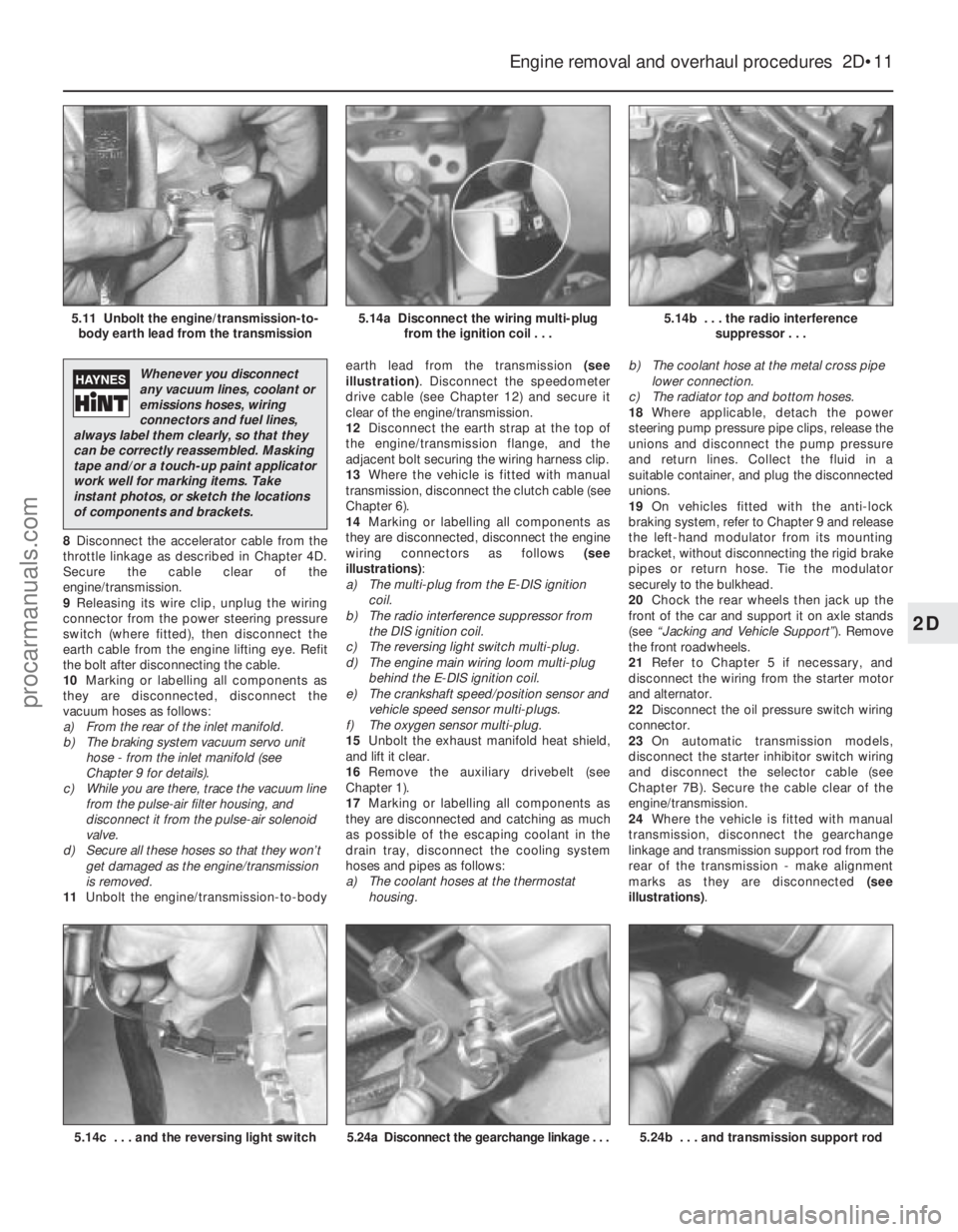
11 Unbolt the engine/transmission-to-body earth lead from the transmission
(see
illustration) . Disconnect the speedometer
drive cable (see Chapter 12) and secure it
clear of the engine/transmission.
12 Disconnect the earth strap at the top of
the engine/transmission flange, and the
adjacent bolt securing the wiring harness clip.
13 Where the vehicle is fitted with manual
transmission, disconnect the clutch cable (see
Chapter 6).
14 Marking or labelling all components as
they are disconnected, disconnect the engine
wiring connectors as follows (see
illustrations) :
a) The multi-plug from the E-DIS ignition
coil.
b) The radio interference suppressor from
the DIS ignition coil.
c) The reversing light switch multi-plug.
d) The engine main wiring loom multi-plug
behind the E-DIS ignition coil.
e) The crankshaft speed/position sensor and vehicle speed sensor multi-plugs.
f) The oxygen sensor multi-plug.
15 Unbolt the exhaust manifold heat shield,
and lift it clear.
16 Remove the auxiliary drivebelt (see
Chapter 1).
17 Marking or labelling all components as
they are disconnected and catching as much
as possible of the escaping coolant in the
drain tray, disconnect the cooling system
hoses and pipes as follows:
a) The coolant hoses at the thermostat housing. b)
The coolant hose at the metal cross pipe
lower connection.
c) The radiator top and bottom hoses.
18 Where applicable, detach the power
steering pump pressure pipe clips, release the
unions and disconnect the pump pressure
and return lines. Collect the fluid in a
suitable container, and plug the disconnected
unions.
19 On vehicles fitted with the anti-lock
braking system, refer to Chapter 9 and release
the left-hand modulator from its mounting
bracket, without disconnecting the rigid brake
pipes or return hose. Tie the modulator
securely to the bulkhead.
20 Chock the rear wheels then jack up the
front of the car and support it on axle stands
(see “Jacking and Vehicle Support” ). Remove
the front roadwheels.
21 Refer to Chapter 5 if necessary, and
disconnect the wiring from the starter motor
and alternator.
22 Disconnect the oil pressure switch wiring
connector.
23 On automatic transmission models,
disconnect the starter inhibitor switch wiring
and disconnect the selector cable (see
Chapter 7B). Secure the cable clear of the
engine/transmission.
24 Where the vehicle is fitted with manual
transmission, disconnect the gearchange
linkage and transmission support rod from the
rear of the transmission - make alignment
marks as they are disconnected (see
illustrations) .
Engine removal and overhaul procedures 2D•11
5.14b . . . the radio interference
suppressor . . .5.14a Disconnect the wiring multi-plugfrom the ignition coil . . .5.11 Unbolt the engine/transmission-to-body earth lead from the transmission
5.24b . . . and transmission support rod5.24a Disconnect the gearchange linkage . . .5.14c . . . and the reversing light switch
2D
1595Ford Fiesta Remake
Whenever you disconnect
any vacuum lines, coolant or
emissions hoses, wiring
connectors and fuel lines,
always label them clearly, so that they
can be correctly reassembled. Masking
tape and/or a touch-up paint applicator
work well for marking items. Take
instant photos, or sketch the locations
of components and brackets.
procarmanuals.com
http://vnx.su
Page 124 of 296
4B
1595Ford Fiesta Remake
General
System type . . . . . . . . . . . . . . . . . . . . . . . . . . . . . . . . . . . .\
. . . . . . . . . . Central Fuel injection (CFi)
Application . . . . . . . . . . . . . . . . . . . . . . . . . . . . . . . . . . . .\
. . . . . . . . . . . 1.1 and 1.3 litre HCS engines and 1.4 litre CVH engines
Fuel grade
Fuel octane requirement . . . . . . . . . . . . . . . . . . . . . . . . . . . . . . . . . . . .\
. 95 RON unleaded
Fuel system data
Regulated fuel pressure - engine running at idle speed . . . . . . . . . . . . . 1.0 ± 0.1 bars
Hold pressure - engine stopped after 1 minute . . . . . . . . . . . . . . . . . . . 0.5 bars minimum
Torque wrench settingsNmlbf ft
CFi unit-to-inlet manifold . . . . . . . . . . . . . . . . . . . . . . . . . . . . . . . . . . . .\
12 to 15 9 to 11
Inlet manifold . . . . . . . . . . . . . . . . . . . . . . . . . . . . . . . . . . . .\
. . . . . . . . . 16 to 20 12 to 15
Inlet air temperature sensor . . . . . . . . . . . . . . . . . . . . . . . . . . . . . . . . . . 20 to 25 15 to 18
Oxygen sensor . . . . . . . . . . . . . . . . . . . . . . . . . . . . . . . . . . . .\
. . . . . . . . 50 to 70 37 to 52
Chapter 4 Part B:
Fuel system - central fuel injection engines
Accelerator cable - removal, refitting and adjustment . . . . . . . . . . . 5
Accelerator pedal - removal and refitting . . . . . . . . . . . . . . . . . . . . . 6
Air cleaner assembly and air inlet components - removal and refitting . . . . . . . . . . . . . . . . . . . . . . . . . . . . . . . . . . . .\
. . . . . . . . . . 4
Air cleaner element renewal . . . . . . . . . . . . . . . . . . . . . .See Chapter 1
Fuel cut-off switch - removal and refitting . . . . . . . . . . . . . . . . . . . . 12
Fuel filter renewal . . . . . . . . . . . . . . . . . . . . . . . . . . \
. . . . .See Chapter 1
Fuel injection system - checking . . . . . . . . . . . . . . . . . . . . . . . . . . . . 13
Fuel injection system components - removal and refitting . . . . . . . . 14
Fuel lines and fittings - general information . . . . . . . . . . . . . . . . . . . 3
Fuel pump/fuel gauge sender unit - removal and refitting . . . . . . . . 9 Fuel pump/fuel pressure - checking . . . . . . . . . . . . . . . . . . . . . . . . . 7
Fuel system - depressurisation . . . . . . . . . . . . . . . . . . . . . . . . . . . . . 2
Fuel tank - removal, inspection and refitting . . . . . . . . . . . . . . . . . . . 8
Fuel tank filler pipe - removal and refitting . . . . . . . . . . . . . . . . . . . . 11
Fuel tank ventilation tube - removal and refitting . . . . . . . . . . . . . . . 10
General fuel system checks . . . . . . . . . . . . . . . . . . . . . .See Chapter 1
General information and precautions . . . . . . . . . . . . . . . . . . . . . . . . 1
Inlet manifold - removal and refitting . . . . . . . . . . . . . . . . . . . . . . . . 15
Underbody fuel/brake line check . . . . . . . . . . . . . . . . . . .See\
Chapter 1
Underbonnet check for fluid leaks and hose condition . .See Chapter 1
4B•1
Specifications Contents
Easy,
suitable for
novice with little
experience Fairly easy,
suitable
for beginner with
some experience Fairly difficult,
suitable for competent
DIY mechanic
Difficult,
suitable for
experienced DIY
mechanic Very difficult,
suitable for expert DIY
or professional
Degrees of difficulty
54321
procarmanuals.com
http://vnx.su