1989 FORD FIESTA catalytic converter
[x] Cancel search: catalytic converterPage 8 of 296
Maintenance – component location1•7
1
1595Ford Fiesta Remake
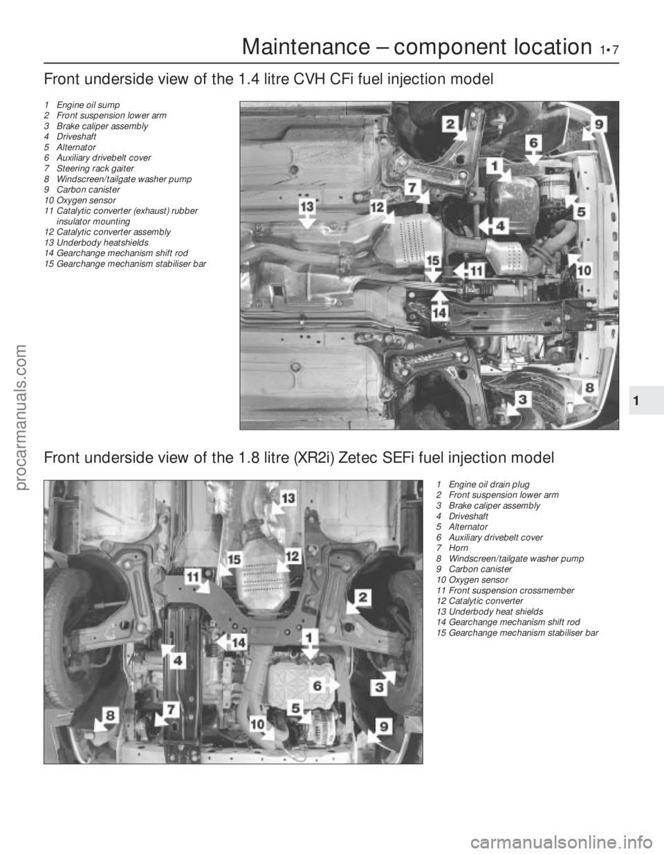
Front underside view of the 1.4 litre CVH CFi fuel injection model
1 Engine oil sump
2 Front suspension lower arm
3 Brake caliper assembly
4 Driveshaft
5 Alternator
6 Auxiliary drivebelt cover
7 Steering rack gaiter
8 Windscreen/tailgate washer pump
9 Carbon canister
10 Oxygen sensor
11 Catalytic converter (exhaust) rubber
insulator mounting
12 Catalytic converter assembly
13 Underbody heatshields
14 Gearchange mechanism shift rod
15 Gearchange mechanism stabiliser bar
Front underside view of the 1.8 litre (XR2i) Zetec SEFi fuel injection model
1 Engine oil drain plug
2 Front suspension lower arm
3 Brake caliper assembly
4 Driveshaft
5 Alternator
6 Auxiliary drivebelt cover
7 Horn
8 Windscreen/tailgate washer pump
9 Carbon canister
10 Oxygen sensor
11 Front suspension crossmember
12 Catalytic converter
13 Underbody heat shields
14 Gearchange mechanism shift rod
15 Gearchange mechanism stabiliser bar
procarmanuals.com
http://vnx.su
Page 18 of 296
point at the engine to the end of the tailpipe.
Ideally, this should be done on a hoist, where
unrestricted access is available; if a hoist is
not available, raise and support the vehicle on
axle stands.
2Check the pipes and connections for
evidence of leaks, severe corrosion, or
damage. Make sure that all brackets and
rubber mountings are in good condition, and
tight; if any of the mountings are to be
renewed, ensure that the replacements are of
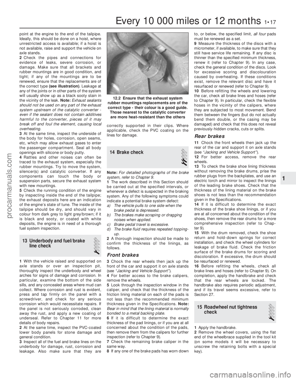
the correct type (see illustration) . Leakage at
any of the joints or in other parts of the system
will usually show up as a black sooty stain in
the vicinity of the leak. Note: Exhaust sealants
should not be used on any part of the exhaust
system upstream of the catalytic converter -
even if the sealant does not contain additives
harmful to the converter, pieces of it may
break off and foul the element, causing local
overheating.
3 At the same time, inspect the underside of
the body for holes, corrosion, open seams,
etc, which may allow exhaust gases to enter
the passenger compartment. Seal all body
openings with silicone or body putty.
4 Rattles and other noises can often be
traced to the exhaust system, especially the
rubber mountings. Try to move the system,
silencer(s) and catalytic converter. If any
components can touch the body or
suspension parts, secure the exhaust system
with new mountings.
5 Check the running condition of the engine
by inspecting inside the end of the tailpipe;
the exhaust deposits here are an indication
of the engine’s state of tune. The inside of the
tailpipe should be dry, and should vary in
colour from dark grey to light grey/brown; if it
is black and sooty, or coated with white
deposits, the engine is in need of a thorough
fuel system inspection.
13 Underbody and fuel/brake line check
1
1With the vehicle raised and supported on
axle stands or over an inspection pit,
thoroughly inspect the underbody and wheel
arches for signs of damage and corrosion. In
particular, examine the bottom of the side
sills, and any concealed areas where mud can
collect. Where corrosion and rust is evident,
press and tap firmly on the panel with a
screwdriver, and check for any serious
corrosion which would necessitate repairs. If
the panel is not seriously corroded, clean
away the rust, and apply a new coating of
underseal. Refer to Chapter 11 for more
details of body repairs.
2 At the same time, inspect the PVC-coated
lower body panels for stone damage and
general condition.
3 Inspect all of the fuel and brake lines on the
underbody for damage, rust, corrosion and
leakage. Also make sure that they are correctly supported in their clips. Where
applicable, check the PVC coating on the
lines for damage.
14 Brake check
2
Note:
For detailed photographs of the brake
system, refer to Chapter 9.
1 The work described in this Section should
be carried out at the specified intervals, or
whenever a defect is suspected in the braking
system. Any of the following symptoms could
indicate a potential brake system defect:
a) The vehicle pulls to one side when the brake pedal is depressed.
b) The brakes make scraping or dragging
noises when applied.
c) Brake pedal travel is excessive.
d) The brake fluid requires repeated topping-
up.
2 A thorough inspection should be made to
confirm the thickness of the linings, as
follows.
Front brakes
3 Chock the rear wheels then jack up the
front of the car and support it on axle stands
(see “Jacking and Vehicle Support” ).
4 For better access to the brake calipers,
remove the wheels.
5 Look through the inspection window in the
caliper, and check that the thickness of the
friction lining material on each of the pads is
not less than the recommended minimum
thickness given in the Specifications. Note:
Bear in mind that the lining material is normally
bonded to a metal backing plate.
6 If it is difficult to determine the exact
thickness of the pad linings, or if you are at all
concerned about the condition of the pads,
then remove them from the calipers for further
inspection (refer to Chapter 9).
7 Check the remaining brake caliper in the
same way.
8 If any one of the brake pads has worn down to, or below, the specified limit,
all fourpads
must be renewed as a set.
9 Measure the thickness of the discs with a
micrometer, if available, to make sure that they
still have service life remaining. If any disc is
thinner than the specified minimum thickness,
renew it (refer to Chapter 9). In any case,
check the general condition of the discs. Look
for excessive scoring and discolouration
caused by overheating. If these conditions
exist, remove the relevant disc and have it
resurfaced or renewed (refer to Chapter 9).
10 Before refitting the wheels and lowering
the car, check all brake lines and hoses (refer
to Chapter 9). In particular, check the flexible
hoses in the vicinity of the calipers, where
they are subjected to most movement. Bend
them between the fingers (but do not actually
bend them double, or the casing may be
damaged) and check that this does not reveal
previously-hidden cracks, cuts or splits.
Rear brakes
11 Chock the front wheels then jack up the
rear of the car and support it on axle stands
(see “Jacking and Vehicle Support” ).
12 For better access, remove the rear
wheels.
13 To check the brake shoe lining thickness
without removing the brake drums, prise the
rubber plugs from the backplates, and use an
electric torch and mirror to inspect the linings
of the leading brake shoes. Check that the
thickness of the lining material on the brake
shoes is not less than the recommendation
given in the Specifications.
14 If it is difficult to determine the exact
thickness of the brake shoe linings, or if you
are at all concerned about the condition of the
shoes, then remove the rear drums for a more
comprehensive inspection (refer to Chap-
ter 9).
15 With the drum removed, check the shoe
return and hold-down springs for correct
installation, and check the wheel cylinders for
leakage of brake fluid. Check the friction
surface of the brake drums for scoring and
discoloration. If excessive, the drum should
be resurfaced or renewed.
16 Before refitting the wheels, check all
brake lines and hoses (refer to Chapter 9). On
completion, apply the handbrake and check
that the rear wheels are locked. The
handbrake also requires periodic adjustment,
and if its travel seems excessive, refer to
Section 27.
15 Roadwheel nut tightness check
1
1Apply the handbrake.
2 Remove the wheel covers, using the flat
end of the wheelbrace supplied in the tool kit
(on some models it will be necessary to
unscrew the retaining bolts with a special
key).
Every 10 000 miles or 12 months1•17
12.2 Ensure that the exhaust system
rubber mountings replacements are of the correct type - their colour is a good guide. Those nearest to the catalytic converterare more heat-resistant than the others
1
1595Ford Fiesta Remakeprocarmanuals.com
http://vnx.su
Page 34 of 296
cover). Using a new gasket, fit the timing
chain cover, centring it with the aid of the
crankshaft pulley - lubricate the seal contact
surfaces beforehand. Refit and tighten the
retaining bolts but, where applicable, leave
out the timing cover bolt which also secures
the water pump at this stage.
8Where applicable, refit the water pump as
described in Chapter 3.
9 Refit the crankshaft pulley as described in
the previous Section.
10 Refit the sump as described in Section 11.
10Timing chain, sprockets and
tensioner - removal,
inspection and refitting
3
Removal
1 Remove the timing chain cover as
described in the previous Section.
2 Remove the oil slinger from the front face of
the crankshaft, noting its orientation (see
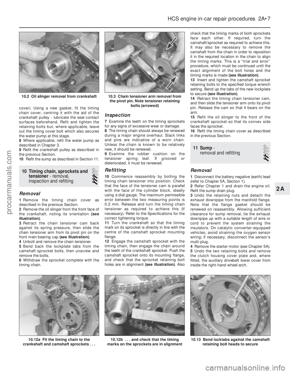
illustration) .
3 Retract the chain tensioner cam back
against its spring pressure, then slide the
chain tensioner arm from its pivot pin on the
front main bearing cap (see illustration).
4 Unbolt and remove the chain tensioner.
5 Bend back the lockplate tabs from the
camshaft sprocket bolts, then unscrew and
remove the bolts.
6 Withdraw the sprocket complete with the
timing chain.
Inspection
7 Examine the teeth on the timing sprockets
for any signs of excessive wear or damage.
8 The timing chain should always be renewed
during a major engine overhaul. Slack links
and pins are indicative of a worn chain.
Unless the chain is known to be relatively
new, it should be renewed.
9 Examine the rubber cushion on the
tensioner spring leaf. If grooved or
deteriorated, it must be renewed.
Refitting
10 Commence reassembly by bolting the
timing chain tensioner into position. Check
that the face of the tensioner cam is parallel
with the face of the cylinder block, ideally
using a dial gauge. The maximum permissible
error between the two measuring points is
0.2 mm. Release and turn the timing chain
tensioner as required to achieve this (if
necessary). Refer to the Specifications for the
correct tightening torque.
11 Turn the crankshaft so that the timing
mark on its sprocket is directly in line with the
centre of the camshaft sprocket mounting
flange.
12 Engage the camshaft sprocket with the
timing chain, then engage the chain around
the teeth of the crankshaft sprocket. Push the
camshaft sprocket onto its mounting flange,
and check that the sprocket retaining bolt
holes are in alignment (see illustration). Alsocheck that the timing marks of both sprockets
face each other. If required, turn the
camshaft/sprocket as required to achieve this.
It may also be necessary to remove the
camshaft from the chain in order to reposition
it in the required location in the chain to align
the timing marks. This is a “trial and error”
procedure, which must be continued until the
exact alignment of the bolt holes and the
timing marks is made
(see illustration).
13 Insert and tighten the camshaft sprocket
retaining bolts to the specified torque wrench
setting. Bend up the tabs of the new lockplate
to secure (see illustration) .
14 Retract the timing chain tensioner cam,
and then slide the tensioner arm onto its pivot
pin. Release the cam so that it bears on the
arm.
15 Refit the oil slinger to the front of the
crankshaft sprocket so that its convex side
faces the sprocket.
16 Refit the timing chain cover as described
in the previous Section.
11 Sump -
removal and refitting
2
Removal
1 Disconnect the battery negative (earth) lead
(refer to Chapter 5A, Section 1).
2 Refer Chapter 1 and drain the engine oil.
Refit the sump drain plug.
3 Undo the retaining nuts and detach the
exhaust downpipe from the manifold flange.
Note that the flange gasket should be
renewed on reassembly. Allowing sufficient
clearance for sump removal, tie the exhaust
downpipe up with a suitable length of wire or
cord to prevent the system straining the
insulators. On catalytic converter-equipped
vehicles, avoid straining the oxygen sensor
wiring; if necessary, disconnect the sensor’s
multi-plug.
4 Remove the starter motor (see Chapter 5A).
5 Undo the two retaining bolts and remove
the clutch housing cover plate and, where
fitted, the auxiliary drivebelt lower cover from
inside the right-hand wheel arch.
HCS engine in-car repair procedures 2A•7
10.12a Fit the timing chain to the
crankshaft and camshaft sprockets . . .
10.3 Chain tensioner arm removal from the pivot pin. Note tensioner retaining bolts (arrowed)10.2 Oil slinger removal from crankshaft
10.13 Bend locktabs against the camshaftretaining bolt heads to secure10.12b . . . and check that the timing
marks on the sprockets are in alignment
2A
1595Ford Fiesta Remakeprocarmanuals.com
http://vnx.su
Page 49 of 296
be fitted on reassembly. Tie the downpipe up
to support it.
18Before it is released and removed, the
cylinder head must first have cooled down to
room temperature (about 20ºC).
19 Unscrew the cylinder head retaining bolts
progressively in the reverse order to that
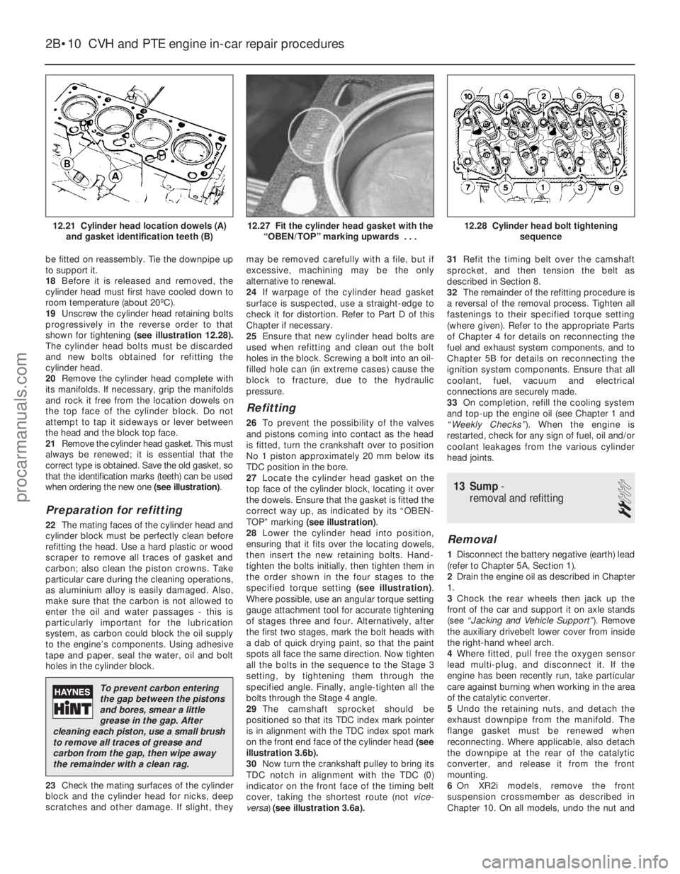
shown for tightening (see illustration 12.28).
The cylinder head bolts must be discarded
and new bolts obtained for refitting the
cylinder head.
20 Remove the cylinder head complete with
its manifolds. If necessary, grip the manifolds
and rock it free from the location dowels on
the top face of the cylinder block. Do not
attempt to tap it sideways or lever between
the head and the block top face.
21 Remove the cylinder head gasket. This must
always be renewed; it is essential that the
correct type is obtained. Save the old gasket, so
that the identification marks (teeth) can be used
when ordering the new one (see illustration).
Preparation for refitting
22The mating faces of the cylinder head and
cylinder block must be perfectly clean before
refitting the head. Use a hard plastic or wood
scraper to remove all traces of gasket and
carbon; also clean the piston crowns. Take
particular care during the cleaning operations,
as aluminium alloy is easily damaged. Also,
make sure that the carbon is not allowed to
enter the oil and water passages - this is
particularly important for the lubrication
system, as carbon could block the oil supply
to the engine’s components. Using adhesive
tape and paper, seal the water, oil and bolt
holes in the cylinder block.
23 Check the mating surfaces of the cylinder
block and the cylinder head for nicks, deep
scratches and other damage. If slight, they may be removed carefully with a file, but if
excessive, machining may be the only
alternative to renewal.
24
If warpage of the cylinder head gasket
surface is suspected, use a straight-edge to
check it for distortion. Refer to Part D of this
Chapter if necessary.
25 Ensure that new cylinder head bolts are
used when refitting and clean out the bolt
holes in the block. Screwing a bolt into an oil-
filled hole can (in extreme cases) cause the
block to fracture, due to the hydraulic
pressure.
Refitting
26 To prevent the possibility of the valves
and pistons coming into contact as the head
is fitted, turn the crankshaft over to position
No 1 piston approximately 20 mm below its
TDC position in the bore.
27 Locate the cylinder head gasket on the
top face of the cylinder block, locating it over
the dowels. Ensure that the gasket is fitted the
correct way up, as indicated by its “OBEN-
TOP” marking (see illustration) .
28 Lower the cylinder head into position,
ensuring that it fits over the locating dowels,
then insert the new retaining bolts. Hand-
tighten the bolts initially, then tighten them in
the order shown in the four stages to the
specified torque setting (see illustration).
Where possible, use an angular torque setting
gauge attachment tool for accurate tightening
of stages three and four. Alternatively, after
the first two stages, mark the bolt heads with
a dab of quick drying paint, so that the paint
spots all face the same direction. Now tighten
all the bolts in the sequence to the Stage 3
setting, by tightening them through the
specified angle. Finally, angle-tighten all the
bolts through the Stage 4 angle.
29 The camshaft sprocket should be
positioned so that its TDC index mark pointer
is in alignment with the TDC index spot mark
on the front end face of the cylinder head (see
illustration 3.6b).
30 Now turn the crankshaft pulley to bring its
TDC notch in alignment with the TDC (0)
indicator on the front face of the timing belt
cover, taking the shortest route (not vice-
versa) (see illustration 3.6a). 31
Refit the timing belt over the camshaft
sprocket, and then tension the belt as
described in Section 8.
32 The remainder of the refitting procedure is
a reversal of the removal process. Tighten all
fastenings to their specified torque setting
(where given). Refer to the appropriate Parts
of Chapter 4 for details on reconnecting the
fuel and exhaust system components, and to
Chapter 5B for details on reconnecting the
ignition system components. Ensure that all
coolant, fuel, vacuum and electrical
connections are securely made.
33 On completion, refill the cooling system
and top-up the engine oil (see Chapter 1 and
“Weekly Checks” ). When the engine is
restarted, check for any sign of fuel, oil and/or
coolant leakages from the various cylinder
head joints.
13 Sump -
removal and refitting
2
Removal
1 Disconnect the battery negative (earth) lead
(refer to Chapter 5A, Section 1).
2 Drain the engine oil as described in Chapter
1.
3 Chock the rear wheels then jack up the
front of the car and support it on axle stands
(see “Jacking and Vehicle Support” ). Remove
the auxiliary drivebelt lower cover from inside
the right-hand wheel arch.
4 Where fitted, pull free the oxygen sensor
lead multi-plug, and disconnect it. If the
engine has been recently run, take particular
care against burning when working in the area
of the catalytic converter.
5 Undo the retaining nuts, and detach the
exhaust downpipe from the manifold. The
flange gasket must be renewed when
reconnecting. Where applicable, also detach
the downpipe at the rear of the catalytic
converter, and release it from the front
mounting.
6 On XR2i models, remove the front
suspension crossmember as described in
Chapter 10. On all models, undo the nut and
2B•10 CVH and PTE engine in-car repair procedures
12.28 Cylinder head bolt tightening
sequence12.27 Fit the cylinder head gasket with the“OBEN/TOP” marking upwards . . .12.21 Cylinder head location dowels (A)and gasket identification teeth (B)
1595Ford Fiesta Remake
To prevent carbon entering
the gap between the pistons
and bores, smear a little
grease in the gap. After
cleaning each piston, use a small brush
to remove all traces of grease and
carbon from the gap, then wipe away
the remainder with a clean rag.
procarmanuals.com
http://vnx.su
Page 65 of 296
25As the cylinder head is such a heavy and
awkward assembly to refit with manifolds, it is
helpful to make up a pair of guide studs from
two 10 mm (thread size) studs approximately
90 mm long, with a screwdriver slot cut in one
end - two old cylinder head bolts with their
heads cut off would make a good starting
point. Screw these guide studs, screwdriver
slot upwards to permit removal, into the bolt
holes at diagonally-opposite corners of the
cylinder block surface (or into those where the
locating dowels are fitted); ensure that
approximately 70 mm of stud protrudes
above the gasket.
26 Refit the cylinder head, sliding it down the
guide studs (if used) and locating it on the
dowels. Unscrew the guide studs (if used)
when the head is in place.
27 Fit the new cylinder head bolts dry ( do not
oil their threads); carefully enter each into its
hole and screw it in, by hand only, until finger-
tight.
28 Working progressively and in the
sequence shown, use first a torque wrench,
then an ordinary socket extension bar and an
angle gauge, to tighten the cylinder head bolts
in the stages given in the Specifications
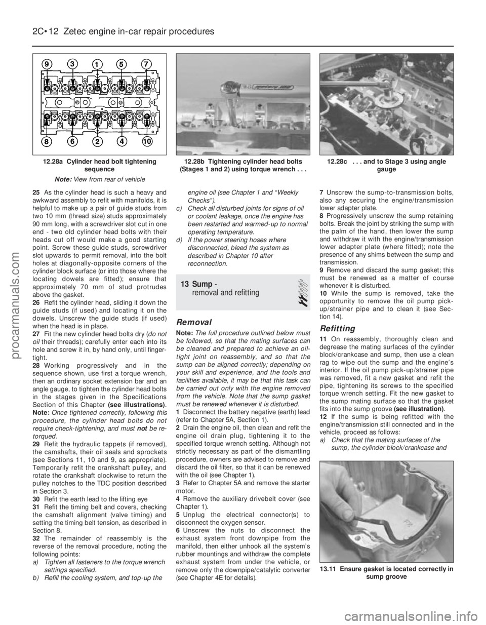
Section of this Chapter (see illustrations).
Note: Once tightened correctly, following this
procedure, the cylinder head bolts do not
require check-tightening, and must notbe re-
torqued.
29 Refit the hydraulic tappets (if removed),
the camshafts, their oil seals and sprockets
(see Sections 11, 10 and 9, as appropriate).
Temporarily refit the crankshaft pulley, and
rotate the crankshaft clockwise to return the
pulley notches to the TDC position described
in Section 3.
30 Refit the earth lead to the lifting eye
31 Refit the timing belt and covers, checking
the camshaft alignment (valve timing) and
setting the timing belt tension, as described in
Section 8.
32 The remainder of reassembly is the
reverse of the removal procedure, noting the
following points:
a) Tighten all fasteners to the torque wrench settings specified.
b) Refill the cooling system, and top-up the engine oil (see Chapter 1 and “Weekly
Checks”).
c) Check all disturbed joints for signs of oil or coolant leakage, once the engine has
been restarted and warmed-up to normal
operating temperature.
d) If the power steering hoses where
disconnected, bleed the system as
described in Chapter 10 after
reconnection.
13 Sump -
removal and refitting
2
Removal
Note: The full procedure outlined below must
be followed, so that the mating surfaces can
be cleaned and prepared to achieve an oil-
tight joint on reassembly, and so that the
sump can be aligned correctly; depending on
your skill and experience, and the tools and
facilities available, it may be that this task can
be carried out only with the engine removed
from the vehicle. Note that the sump gasket
must be renewed whenever it is disturbed.
1 Disconnect the battery negative (earth) lead
(refer to Chapter 5A, Section 1).
2 Drain the engine oil, then clean and refit the
engine oil drain plug, tightening it to the
specified torque wrench setting. Although not
strictly necessary as part of the dismantling
procedure, owners are advised to remove and
discard the oil filter, so that it can be renewed
with the oil (see Chapter 1).
3 Refer to Chapter 5A and remove the starter
motor.
4 Remove the auxiliary drivebelt cover (see
Chapter 1).
5 Unplug the electrical connector(s) to
disconnect the oxygen sensor.
6 Unscrew the nuts to disconnect the
exhaust system front downpipe from the
manifold, then either unhook all the system’s
rubber mountings and withdraw the complete
exhaust system from under the vehicle, or
remove only the downpipe/catalytic converter
(see Chapter 4E for details). 7
Unscrew the sump-to-transmission bolts,
also any securing the engine/transmission
lower adapter plate.
8 Progressively unscrew the sump retaining
bolts. Break the joint by striking the sump with
the palm of the hand, then lower the sump
and withdraw it with the engine/transmission
lower adapter plate (where fitted); note the
presence of any shims between the sump and
transmission.
9 Remove and discard the sump gasket; this
must be renewed as a matter of course
whenever it is disturbed.
10 While the sump is removed, take the
opportunity to remove the oil pump pick-
up/strainer pipe and to clean it (see Sec-
tion 14).Refitting
11 On reassembly, thoroughly clean and
degrease the mating surfaces of the cylinder
block/crankcase and sump, then use a clean
rag to wipe out the sump and the engine’s
interior. If the oil pump pick-up/strainer pipe
was removed, fit a new gasket and refit the
pipe, tightening its screws to the specified
torque wrench setting. Fit the new gasket to
the sump mating surface so that the gasket
fits into the sump groove (see illustration).
12 If the sump is being refitted with the
engine/transmission still connected and in the
vehicle, proceed as follows:
a) Check that the mating surfaces of the sump, the cylinder block/crankcase and
2C•12 Zetec engine in-car repair procedures
13.11 Ensure gasket is located correctly in sump groove
12.28c . . . and to Stage 3 using angle gauge12.28b Tightening cylinder head bolts
(Stages 1 and 2) using torque wrench . . .12.28a Cylinder head bolt tightening sequence
Note: View from rear of vehicle
1595Ford Fiesta Remakeprocarmanuals.com
http://vnx.su
Page 78 of 296
7Refer to the relevant Part of Chapter 4 for
details, and disconnect the accelerator cable
from the throttle linkage and support/adjuster
bracket. Where applicable, also disconnect
the choke cable. Position the cable(s) out of
the way.
8 On carburettor models, disconnect the fuel
supply hose from the fuel pump, and the
return hose from the carburettor.
9 On CFi models, detach the fuel hose at the
injector/pressure regulator unit, and the return
line, by compressing the couplings whilst
pulling the hoses free from their connections.
On EFi and SEFi models, unscrew the union
nut to detach the fuel line from the fuel rail;
release the retaining clip to detach the return
pipe from the pressure regulator. Plug the
exposed ends of the hoses and connections,
to prevent fuel spillage and the ingress of dirt.
Position the hoses out of the way.
10 Press the clamp ring inwards, and
simultaneously pull free the brake servo hose from the inlet manifold. Position it out of the
way.
11
On CFi and EFi models, detach the
vacuum hose from the MAP sensor, and the
hose between the carbon canister and the fuel
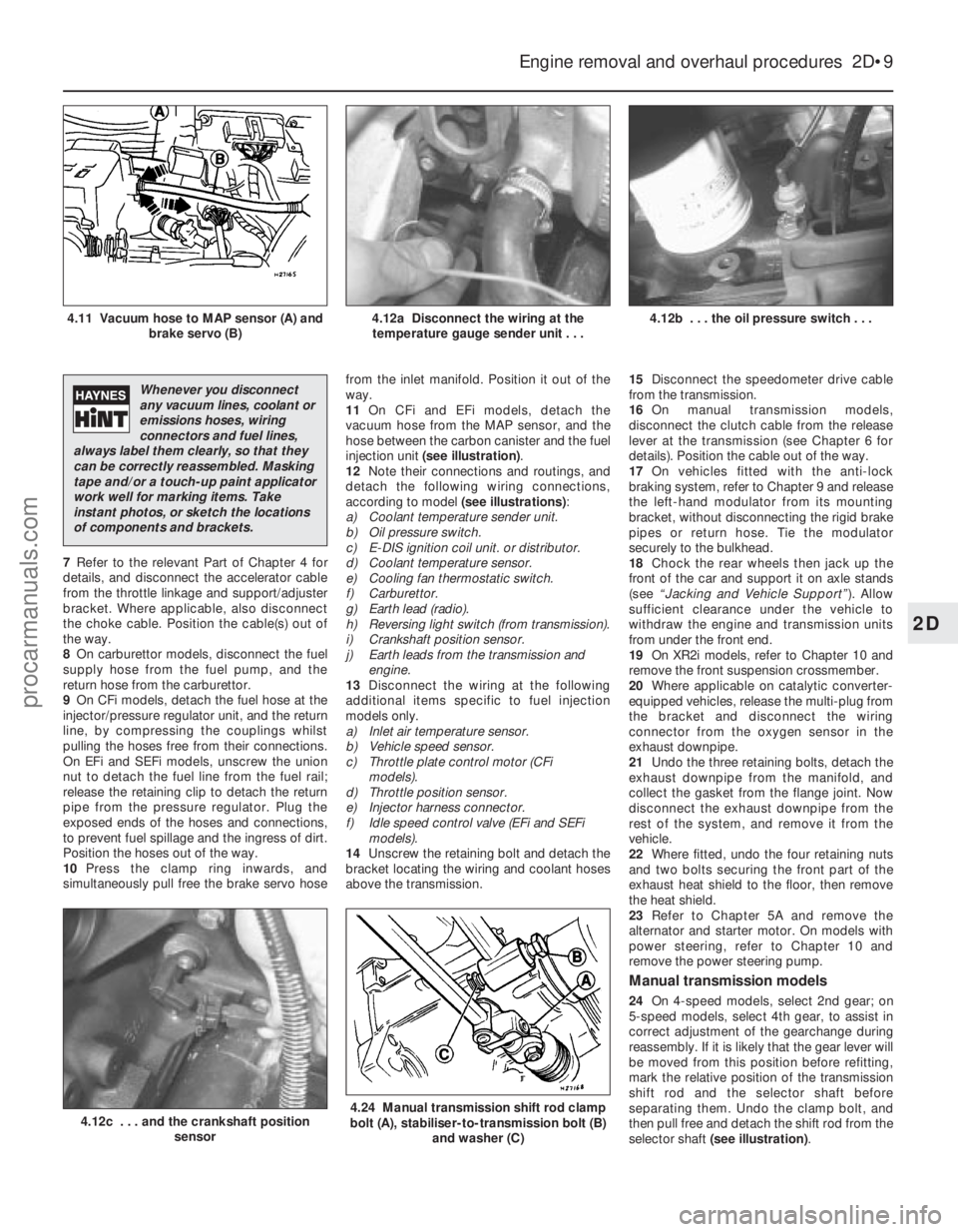
injection unit (see illustration) .
12 Note their connections and routings, and
detach the following wiring connections,
according to model (see illustrations):
a) Coolant temperature sender unit.
b) Oil pressure switch.
c) E-DIS ignition coil unit. or distributor.
d) Coolant temperature sensor.
e) Cooling fan thermostatic switch.
f) Carburettor.
g) Earth lead (radio).
h) Reversing light switch (from transmission).
i) Crankshaft position sensor.
j) Earth leads from the transmission and engine.
13 Disconnect the wiring at the following
additional items specific to fuel injection
models only.
a) Inlet air temperature sensor.
b) Vehicle speed sensor.
c) Throttle plate control motor (CFi models).
d) Throttle position sensor.
e) Injector harness connector.
f) Idle speed control valve (EFi and SEFi models).
14 Unscrew the retaining bolt and detach the
bracket locating the wiring and coolant hoses
above the transmission. 15
Disconnect the speedometer drive cable
from the transmission.
16 On manual transmission models,
disconnect the clutch cable from the release
lever at the transmission (see Chapter 6 for
details). Position the cable out of the way.
17 On vehicles fitted with the anti-lock
braking system, refer to Chapter 9 and release
the left-hand modulator from its mounting
bracket, without disconnecting the rigid brake
pipes or return hose. Tie the modulator
securely to the bulkhead.
18 Chock the rear wheels then jack up the
front of the car and support it on axle stands
(see “Jacking and Vehicle Support” ). Allow
sufficient clearance under the vehicle to
withdraw the engine and transmission units
from under the front end.
19 On XR2i models, refer to Chapter 10 and
remove the front suspension crossmember.
20 Where applicable on catalytic converter-
equipped vehicles, release the multi-plug from
the bracket and disconnect the wiring
connector from the oxygen sensor in the
exhaust downpipe.
21 Undo the three retaining bolts, detach the
exhaust downpipe from the manifold, and
collect the gasket from the flange joint. Now
disconnect the exhaust downpipe from the
rest of the system, and remove it from the
vehicle.
22 Where fitted, undo the four retaining nuts
and two bolts securing the front part of the
exhaust heat shield to the floor, then remove
the heat shield.
23 Refer to Chapter 5A and remove the
alternator and starter motor. On models with
power steering, refer to Chapter 10 and
remove the power steering pump.
Manual transmission models
24 On 4-speed models, select 2nd gear; on
5-speed models, select 4th gear, to assist in
correct adjustment of the gearchange during
reassembly. If it is likely that the gear lever will
be moved from this position before refitting,
mark the relative position of the transmission
shift rod and the selector shaft before
separating them. Undo the clamp bolt, and
then pull free and detach the shift rod from the
selector shaft (see illustration) .
Engine removal and overhaul procedures 2D•9
4.12b . . . the oil pressure switch . . .4.12a Disconnect the wiring at the
temperature gauge sender unit . . .4.11 Vacuum hose to MAP sensor (A) and brake servo (B)
4.24 Manual transmission shift rod clamp
bolt (A), stabiliser-to-transmission bolt (B)
and washer (C)4.12c . . . and the crankshaft position sensor
2D
1595Ford Fiesta Remake
Whenever you disconnect
any vacuum lines, coolant or
emissions hoses, wiring
connectors and fuel lines,
always label them clearly, so that they
can be correctly reassembled. Masking
tape and/or a touch-up paint applicator
work well for marking items. Take
instant photos, or sketch the locations
of components and brackets.
procarmanuals.com
http://vnx.su
Page 79 of 296
25Unscrew the retaining bolt, and detach
the shift rod stabiliser from the transmission.
As it is detached, note the washer located
between the stabiliser and the transmission.
Tie the stabiliser and the shift rod up out of
the way.
Automatic transmission models
26 Unclip and detach the wiring connector
from the starter inhibitor switch (on the
transmission housing).
27 Referring to the relevant Part of Chapter 4
for details, unhook the accelerator (cam plate)
cable from the carburettor or fuel injection unit
(as applicable) at the transmission end of
the cable. Undo the retaining bolt and
detach the cable sheath bracket from the
transmission. Detach the cam plate cable
from the link.
28 Undo the two nuts from the selector cable
bracket which connects it to the lever on the
selector shaft. Disconnect the yoke from the
lever on the selector shaft and the cable from
the lever.
29 Unscrew the union nuts, and disconnect
the oil cooler feed and return pipes from the
transmission. Allow for a certain amount of
spillage, and plug the connections to prevent
the ingress of dirt.
All models
30 Unscrew the retaining nut and withdraw
the Torx-type clamp bolt securing the lower
suspension arm to the spindle carrier on each
side.
31 Refer to Chapter 10 for details, and
detach the right-hand and left-hand track rod
end balljoints from the spindle carriers.
32 On vehicles fitted with the anti-lock
braking system, refer to Chapter 9 and release
the right-hand modulator from its mounting
bracket without disconnecting the rigid brake
pipes or return hose. Tie the modulator
securely to the bulkhead. Additionally, undo
the three bolts securing the modulator
bracket.
33 Insert a suitable lever between the right-
hand driveshaft inner joint and the
transmission housing, and prise free the
driveshaft from the transmission; be prepared
for oil spillage from the transmission case
through the vacated driveshaft aperture. As it
is being prised free, simultaneously pull the
roadwheel outwards on that side, to enable
the driveshaft inboard end to separate
from the transmission. Once it is free,
suspend and support the driveshaft from the
steering gear, to prevent unnecessary strain
being placed on the driveshaft joints.
34 Insert a suitable plastic plug (or if
available, an old driveshaft joint), into the
transmission driveshaft aperture, to
immobilise the gears of the differential unit.
35 Proceed as described above in
paragraphs 33 and 34, and disconnect the
left-hand driveshaft from the transmission.
36 Connect a suitable lift hoist and sling to
the engine, connecting to the lifting eyes. When securely connected, take the weight of
the engine/transmission unit so that the
tension is relieved from the mountings.
37
Undo the retaining bolts and nuts and
detach the right-hand engine mounting from
the vehicle body.
38 Undo the four bolts securing the
transmission bearer to the underside of the
vehicle body. The transmission bearer is
removed with the engine/transmission
assembly.
39 Unscrew the three retaining bolts, and
remove the auxiliary drivebelt cover from
under the crankshaft pulley.
40 The engine/transmission unit should now
be ready for removal from the vehicle. Check
that all of the associated connections and
fittings are disconnected from the engine and
transmission, and positioned out of the way.
41 Enlist the aid of an assistant to help
steady and guide the power unit down
through the engine compartment as it is
removed. If available, position a suitable
engine trolley or crawler board under the
engine/transmission so that when lowered,
the power unit can be withdrawn from the
front end of the vehicle, and then moved to
the area where it is to be cleaned and
dismantled. On automatic transmission
models, particular care must be taken not to
damage the transmission fluid pan (sump)
during the removal and subsequent refitting
processes.
42 Carefully lower the engine and
transmission unit, ensuring that no fittings
become snagged. Detach the hoist and
remove the power unit from under the vehicle.
43 Referring to the relevant Part of Chapter 7,
separate the transmission from the engine.
44 While the engine/transmission is removed,
check the mountings; renew them if they are
worn or damaged. Similarly, check the
condition of all coolant and vacuum hoses
and pipes (see Chapter 1). Components that
are normally hidden can now be checked
properly, and should be renewed if there is
any doubt at all about their condition. Where
the vehicle is fitted with manual transmission,
take the opportunity to inspect the clutch
components (see Chapter 6). It is regarded by
many as good working practice to renew the
clutch assembly as a matter of course,
whenever major engine overhaul work is
carried out. Check also the condition of all
components (such as the transmission oil
seals) disturbed on removal, and renew any
that are damaged or worn.
Refitting
45 Refitting is a reversal of removal, however
note the following additional points:
a) Refer to the applicable Chapters and Sections as for removal.
b) Fit new spring clips to the grooves in the
inboard end of the right- and left-hand
driveshaft joints. Lubricate the splines
with transmission oil prior to fitting. c) Renew the exhaust flange gasket when
reconnecting the exhaust. Ensure that all
wires are routed clear of the exhaust
system and, on catalytic converter
models, ensure that the heat shields are
securely and correctly fitted.
d) Ensure that all earth lead connections are
clean and securely made.
e) Tighten all nuts and bolts to the specified torque.
f) Fit a new oil filter, and refill the engine and transmission with oil, with reference to
Chapter 1.
g) Refill the cooling system with reference to Chapter 1.
h) Refit the alternator and starter motor with reference to Chapter 5A.
i) Where applicable, refit the power steering pump with reference to Chapter 10.
46 When engine and transmission refitting is
complete, refer to the procedures described
in Section 19 before restarting the engine.
5 Engine/transmission -
removal and refitting
(Zetec engines)
3
Warning: Petrol is extremely
flammable, so take extra
precautions when disconnecting
any part of the fuel system.
Don’t smoke, or allow naked flames or
bare light bulbs, in or near the work area,
and don’t work in a garage where a
natural-gas appliance (such as a clothes
dryer or water heater) is installed. If you
spill petrol on your skin, rinse it off
immediately. Have a fire extinguisher rated
for petrol fires handy, and know how to
use it.
Note: Read through the entire Section, as well
as reading the advice in Section 2, before
beginning this procedure. The engine and
transmission are removed as a unit, lowered to
the ground and removed from underneath,
then separated outside the vehicle.
Removal
1 Park the vehicle on firm, level ground, apply
the handbrake firmly, and slacken the nuts
securing both front roadwheels.
2 Depressurise the fuel system as described
in Chapter 4D.
3 Disconnect the battery negative (earth) lead
(refer to Chapter 5A, Section 1).
4 Place protective covers on the wings, then
remove the bonnet (see Chapter 11).
5 Drain the cooling system and the engine oil
(see Chapter 1).
6 Remove the air inlet components and the
complete air cleaner assembly as described in
Chapter 4D.
7 Equalise the pressure in the fuel tank by
removing the filler cap, then release the fuel
feed and return quick-release couplings, and
pull the hoses off the fuel pipes. Plug or cap
all open fittings.
2D•10 Engine removal and overhaul procedures
1595Ford Fiesta Remakeprocarmanuals.com
http://vnx.su
Page 81 of 296
25On automatic transmission models, clean
around the unions, then disconnect the fluid
pipes from the transmission. Plug the
openings in the transmission and the pipe
unions after removal.
26 Refer to Chapter 10 and remove the front
suspension crossmember.
27 Unscrew the nuts to disconnect the
exhaust system front downpipe from the
manifold. Undo the nuts securing the catalytic
converter to the rear part of the exhaust
system, and remove the converter and
downpipe assembly.
28 On vehicles fitted with the anti-lock braking
system, refer to Chapter 9 and release the
right-hand modulator from its mounting
bracket without disconnecting the rigid brake
pipes or return hose. Tie the modulator
securely to the bulkhead. Additionally, undo
the three bolts securing the modulator bracket.
29 Disconnect both anti-roll bar links from
their respective suspension struts, and both
track rod end ball joints from their spindle
carriers (see Chapter 10).
30 Unscrew the retaining nut and withdraw
the Torx-type clamp bolt securing the lower
suspension arm to the spindle carrier on each
side.
31 Insert a suitable lever between the right-
hand driveshaft inner joint and the
transmission housing, and prise free the
driveshaft from the transmission; be prepared
for oil spillage from the transmission case
through the vacated driveshaft aperture. As it
is being prised free, simultaneously pull the
roadwheel outwards on that side to enable the
driveshaft inboard end to separate from the
transmission. Once it is free, suspend and
support the driveshaft from the steering gear,
to prevent unnecessary strain being placed on
the driveshaft joints.
32 Insert a suitable plastic plug (or if
available, an old driveshaft joint), into the
transmission driveshaft aperture, to
immobilise the gears of the differential unit.
33 Proceed as described above in
paragraphs 31 and 32, and disconnect the
left-hand driveshaft from the transmission.
34 Remove the oil filter, referring to Chapter 1
if necessary.
35 Connect a suitable lift hoist and sling to
the engine, connecting to the lift eyes. When
securely connected, take the weight of the
engine/transmission unit so that the tension is
relieved from the mountings.
36 Unbolt the engine rear right-hand
mounting from the body (one bolt in the wheel
arch, one nut in the engine compartment),
then unbolt the engine front right-hand
mounting from the alternator mounting
bracket. Unbolt the transmission bearer from
the underbody.
37 The engine/transmission unit should now
be hanging on the hoist only, with all
components which connect it to the rest of
the vehicle disconnected or removed, and
secured well clear of the unit. Make a final
check that this is the case. 38
Lower the engine/transmission to the
ground, and withdraw it from under the
vehicle.
39 Referring to the relevant Part of Chapter 7,
separate the transmission from the engine.
40 While the engine/transmission is removed,
check the mountings; renew them if they are
worn or damaged. Similarly, check the
condition of all coolant and vacuum hoses
and pipes (see Chapter 1); components that
are normally hidden can now be checked
properly, and should be renewed if there is
any doubt at all about their condition. Where
the vehicle is fitted with manual transmission,
take the opportunity to overhaul the clutch
components (see Chapter 6). It is regarded by
many as good working practice to renew the
clutch assembly as a matter of course,
whenever major engine overhaul work is
carried out. Check also the condition of all
components (such as the transmission oil
seals) disturbed on removal, and renew any
that are damaged or worn.
Refitting
41 Refitting is a reversal of removal, however
note the following additional points:
a) Refer to the applicable Chapters and Sections as for removal.
b) Fit new spring clips to the grooves in the
inboard end of the right- and left-hand
driveshaft joints. Lubricate the splines
with transmission oil prior to fitting.
c) Renew the exhaust flange gaskets when reconnecting the exhaust. Ensure that all
wires are routed clear of the exhaust
system, and that the heat shields are
securely and correctly fitted.
d) Ensure that all earth lead connections are
clean and securely made.
e) Tighten all nuts and bolts to the specified
torque.
f) Fit a new oil filter, and refill the engine and transmission with oil, with reference to
Chapter 1.
g) Refill the cooling system with reference to
Chapter 1.
h) Bleed the power steering system with reference to Chapter 10.
42 When engine and transmission refitting is
complete, refer to the procedures described
in Section 19 before restarting the engine.
6 Engine overhaul - preliminary information
It is much easier to dismantle and work on
the engine if it is mounted on a portable
engine stand. These stands can often be hired
from a tool hire shop. Before the engine is
mounted on a stand, the flywheel/driveplate
should be removed so that the stand bolts
can be tightened into the end of the cylinder
block/crankcase. If a stand is not available, it is possible to
dismantle the engine with it suitably supported on a sturdy, workbench or on the
floor. Be careful not to tip or drop the engine
when working without a stand.
If you intend to obtain a reconditioned
engine, all ancillaries must be removed first, to
be transferred to the replacement engine (just
as they will if you are doing a complete engine
overhaul yourself). These components include
the following:
a) Alternator/power steering pump and
mounting brackets.
b) DIS/E-DIS ignition coil unit (and mounting
bracket), distributor, HT leads and spark
plugs.
c) The thermostat and housing cover.
d) Carburettor/fuel injection system
components.
e) Inlet and exhaust manifolds.
f) Oil filter.
g) Fuel pump.
h) Engine mountings.
i) Flywheel/driveplate.
j) Water pump.
Note: When removing the external
components from the engine, pay close
attention to details that may be helpful or
important during refitting. Note the fitted
positions of gaskets, seals, washers, bolts and
other small items. If you are obtaining a “short” engine
(cylinder block/crankcase, crankshaft, pistons
and connecting rods all assembled), then the
cylinder head, timing chain/belt (together with
tensioner, tensioner and idler pulleys and
covers) sump and oil pump will have to be
removed also. If a complete overhaul is planned, the
engine can be dismantled in the order given
below, referring to Part A, B or C of this
Chapter unless otherwise stated.
a) Inlet and exhaust manifolds.
b) Timing chain/belt, tensioner and
sprockets.
c) Cylinder head.
d) Flywheel/driveplate.
e) Sump.
f) Oil pump.
g) Pistons (with connecting rods).
h) Crankshaft.
i) Camshaft and tappets (HCS engines).
7 Cylinder head - dismantling
4
Note:New and reconditioned cylinder heads
are available from the manufacturers, and from
engine overhaul specialists. Due to the fact
that some specialist tools are required for the
dismantling and inspection procedures, and
new components may not be readily available,
it may be more practical and economical for
the home mechanic to purchase a
reconditioned head, rather than to dismantle,
inspect and recondition the original head.
1 Remove the cylinder head as described in
Part A, B or C of this Chapter (as applicable).
2D•12 Engine removal and overhaul procedures
1595Ford Fiesta Remakeprocarmanuals.com
http://vnx.su