1989 FORD FIESTA clock reset
[x] Cancel search: clock resetPage 60 of 296

19Fit the timing belt; if the original is being
refitted, ensure that the marks and notes
made on removal are followed, so that the belt
is refitted the same way round, and to run in
the same direction. Starting at the crankshaft
sprocket, work anti-clockwise around the
camshaft sprockets and tensioner, finishing
off at the rear guide pulley. The front run,
between the crankshaft and the exhaust
camshaft sprockets, mustbe kept taut,
without altering the position either of the
crankshaft or of the camshaft(s) - if necessary,
the position of the camshaft sprockets can be
altered by rotating each on its camshaft
(which remains fixed by the aligning tool).
Where the sprocket is still fastened, use the
holding tool described above to prevent the
sprocket from rotating while its retaining bolt
is slackened - the sprocket can then be
rotated on the camshaft until the belt will slip
into place; retighten the sprocket bolt.
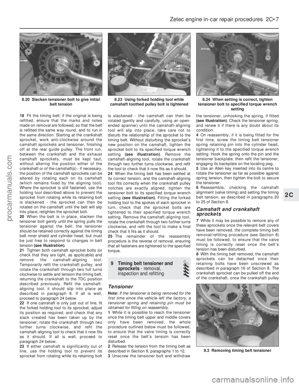
20 When the belt is in place, slacken the
tensioner bolt gently until the spring pulls the
tensioner against the belt; the tensioner
should be retained correctly against the timing
belt inner shield and cylinder head, but must
be just free to respond to changes in belt
tension (see illustration) .
21 Tighten both camshaft sprocket bolts (or
check that they are tight, as applicable) and
remove the camshaft-aligning tool.
Temporarily refit the crankshaft pulley, and
rotate the crankshaft through two full turns
clockwise to settle and tension the timing belt,
returning the crankshaft to the TDC position
described previously. Refit the camshaft-
aligning tool; it should slip into place as
described in paragraph 8. If all is well,
proceed to paragraph 24 below.
22 If one camshaft is only just out of line, fit
the forked holding tool to its sprocket, adjust
its position as required, and check that any
slack created has been taken up by the
tensioner; rotate the crankshaft through two
further turns clockwise, and refit the
camshaft-aligning tool to check that it now fits
as it should. If all is well, proceed to
paragraph 24 below.
23 If either camshaft is significantly out of
line, use the holding tool to prevent its
sprocket from rotating while its retaining bolt is slackened - the camshaft can then be
rotated (gently and carefully, using an open-
ended spanner) until the camshaft-aligning
tool will slip into place; take care not to
disturb the relationship of the sprocket to the
timing belt. Without disturbing the sprocket’s
new position on the camshaft, tighten the
sprocket bolt to its specified torque wrench
setting
(see illustration) . Remove the
camshaft-aligning tool, rotate the crankshaft
through two further turns clockwise, and refit
the tool to check that it now fits as it should.
24 When the timing belt has been settled at
its correct tension, and the camshaft-aligning
tool fits correctly when the crankshaft pulley
notches are exactly aligned, tighten the
tensioner bolt to its specified torque wrench
setting (see illustration) . Fitting the forked
holding tool to the spokes of each sprocket in
turn, check that the sprocket bolts are
tightened to their specified torque wrench
setting. Remove the camshaft-aligning tool,
rotate the crankshaft through two further turns
clockwise, and refit the tool to make a final
check that it fits as it should.
25 The remainder of the reassembly
procedure is the reverse of removal, ensuring
that all fasteners are tightened to the specified
torque.
9 Timing belt tensioner and
sprockets - removal,
inspection and refitting
4
Tensioner
Note: If the tensioner is being removed for the
first time since the vehicle left the factory, a
tensioner spring and retaining pin must be
obtained for fitting on reassembly.
1 While it is possible to reach the tensioner
once the timing belt upper and middle covers
only have been removed, the whole
procedure outlined below must be followed,
to ensure that the valve timing is correctly
reset once the belt’s tension has been
disturbed.
2 Release the tension from the timing belt as
described in Section 8, paragraphs 1 to 12.
3 Unscrew the tensioner bolt and withdraw the tensioner, unhooking the spring, if fitted
(see illustration)
. Check the tensioner spring,
and renew it if there is any doubt about its
condition.
4 On reassembly, if it is being fitted for the
first time, screw the timing belt tensioner
spring retaining pin into the cylinder head,
tightening it to the specified torque wrench
setting. Hook the spring onto the pin and the
tensioner backplate, then refit the tensioner,
engaging its backplate on the locating peg.
5 Use an Allen key inserted into its centre to
rotate the tensioner as far as possible against
spring tension, then tighten the bolt to secure
the tensioner.
6 Reassemble, checking the camshaft
alignment (valve timing) and setting the timing
belt tension, as described in paragraphs 20
to 25 of Section 8.
Camshaft and crankshaft
sprockets
7 While it may be possible to remove any of
these sprockets once the relevant belt covers
have been removed, the complete timing belt
removal/refitting procedure (see Section 8)
must be followed, to ensure that the valve
timing is correctly reset once the belt’s
tension has been disturbed.
8 With the timing belt removed, the camshaft
sprockets can be detached once their
retaining bolts have been unscrewed as
described in paragraph 16 of Section 8. The
crankshaft sprocket can be pulled off the end
of the crankshaft, once the crankshaft pulley
Zetec engine in-car repair procedures 2C•7
8.24 When setting is correct, tighten
tensioner bolt to specified torque wrench setting8.23 Using forked holding tool while
camshaft toothed pulley bolt is tightened8.20 Slacken tensioner bolt to give initial belt tension
9.3 Removing timing belt tensioner
2C
1595Ford Fiesta Remakeprocarmanuals.com
http://vnx.su
Page 147 of 296

7 Fuel pump/fuel pressure-
checking
3
Note: Refer to the warning note in Section 1
before proceeding.
Fuel pump operation check
1 Switch on the ignition, and listen for the fuel
pump (the sound of an electric motor running,
audible from beneath the rear seats).
Assuming there is sufficient fuel in the tank,
the pump should start and run for
approximately one or two seconds, then stop,
each time the ignition is switched on. Note:If
the pump runs continuously all the time the
ignition is switched on, the electronic control
system is running in the backup (or “limp-
home”) mode referred to by Ford as “Limited
Operation Strategy” (LOS). This almost
certainly indicates a fault in the EEC IV module
itself, and the vehicle should therefore be
taken to a Ford dealer for a full test of the
complete system, using the correct diagnostic
equipment; do not waste time or risk
damaging the components by trying to test
the system without such facilities.
2 Listen for fuel return noises from the fuel
pressure regulator. It should be possible to
feel the fuel pulsing in the regulator and in the
feed hose from the fuel filter.
3 If the pump does not run at all, check the
fuse, relay and wiring (see Chapter 12). Check
also that the fuel cut-off switch has not been
activated and if so, reset it.
Fuel pressure check
4 A fuel pressure gauge will be required for
this check and should be connected in the
fuel line between the fuel filter and the fuel rail,
in accordance with the gauge maker’s
instructions. On Zetec engines, a pressure
gauge equipped with an adapter to suit the
Schrader-type valve on the fuel rail pressure
test/release fitting (identifiable by its blue
plastic cap, and located on the union of the
fuel feed line and the fuel rail) will be required.
If the Ford special tool 29-033 is available, the
tool can be attached to the valve, and a
conventional-type pressure gauge attached to
the tool.
5 If using the service tool, ensure that its tap
is turned fully anti-clockwise, then attach it to
the valve. Connect the pressure gauge to the
service tool. If using a fuel pressure gauge
with its own adapter, connect it in accordance
with its maker’s instructions.
6 Start the engine and allow it to idle. Note
the gauge reading as soon as the pressure
stabilises, and compare it with the regulated
fuel pressure figures listed in the
Specifications .
a) If the pressure is high, check for a
restricted fuel return line. If the line is
clear, renew the fuel pressure regulator.
b) If the pressure is low, pinch the fuel return
line. If the pressure now goes up, renew the fuel pressure regulator. If the pressure
does not increase, check the fuel feed
line, the fuel pump and the fuel filter.
7 Detach the vacuum hose from the fuel
pressure regulator; the pressure shown on the
gauge should increase. Note the increase in
pressure, and compare it with that listed in the
Specifications . If the pressure increase is not
as specified, check the vacuum hose and
pressure regulator.
8 Reconnect the regulator vacuum hose, and
switch off the engine. Verify that the hold
pressure stays at the specified level for five
minutes after the engine is turned off.
9 Carefully disconnect the fuel pressure
gauge, depressurising the system first as
described in Section 2. Be sure to cover the
fitting with a rag before slackening it. Mop up
any spilt petrol.
10 Run the engine, and check that there are
no fuel leaks.
8 Fuel tank - removal,
inspection and refitting
3
Proceed as described in Part A, Section 8,
but before disconnecting the battery, relieve
the residual pressure in the fuel system (see
Section 2), and equalise tank pressure by
removing the fuel filler cap.
9 Fuel pump/fuel gauge sender unit - removal and
refitting
3
Refer to Part B, Section 9.
10 Fuel tank ventilation tube -
removal and refitting
3
Refer to Part A, Section 10, but note that
the ventilation tube connects to the combined
roll-over/anti-trickle-fill valve assembly but,
instead of venting to atmosphere, a further
tube runs the length of the vehicle to the
evaporative emission control system carbon canister in the front right-hand corner of the
engine compartment.
Further information on the evaporative
emission control system is contained in Part E
of this Chapter.
11 Fuel tank filler pipe -
removal and refitting
3
Refer to Part A, Section 11.
12 Fuel cut-off switch -
removal and refitting
1
Refer to Part B, Section 12.
13 Fuel injection system -
checking
3
Refer to Part B, Section 13
14 Fuel injection system components - removal and
refitting
3
Note: Refer to the warning note in Section 1
before proceeding.
Throttle housing
1 Disconnect the battery negative (earth) lead
(refer to Chapter 5A, Section 1).
2 Remove the air inlet components as
described in Section 4.
3 Disconnect the accelerator cable from the
throttle linkage (see Section 5).
4 Disconnect the throttle position sensor
multi-plug.
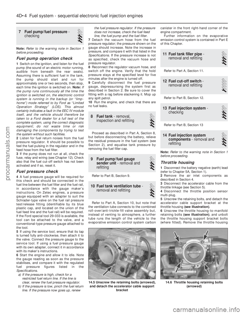
5 Unscrew the retaining bolts, and detach the
accelerator cable support bracket at the
throttle housing (see illustration) .
6 Unscrew the throttle housing-to-manifold
retaining bolts (see illustration) , and unbolt
the throttle housing support bracket bolts
(where fitted). Remove the throttle housing
4D•4 Fuel system - sequential electronic fuel injection engines
14.6 Throttle housing retaining bolts
(arrowed)14.5 Unscrew the retaining bolts (arrowed),and detach the accelerator cable support
bracket
1595Ford Fiesta Remakeprocarmanuals.com
http://vnx.su
Page 245 of 296

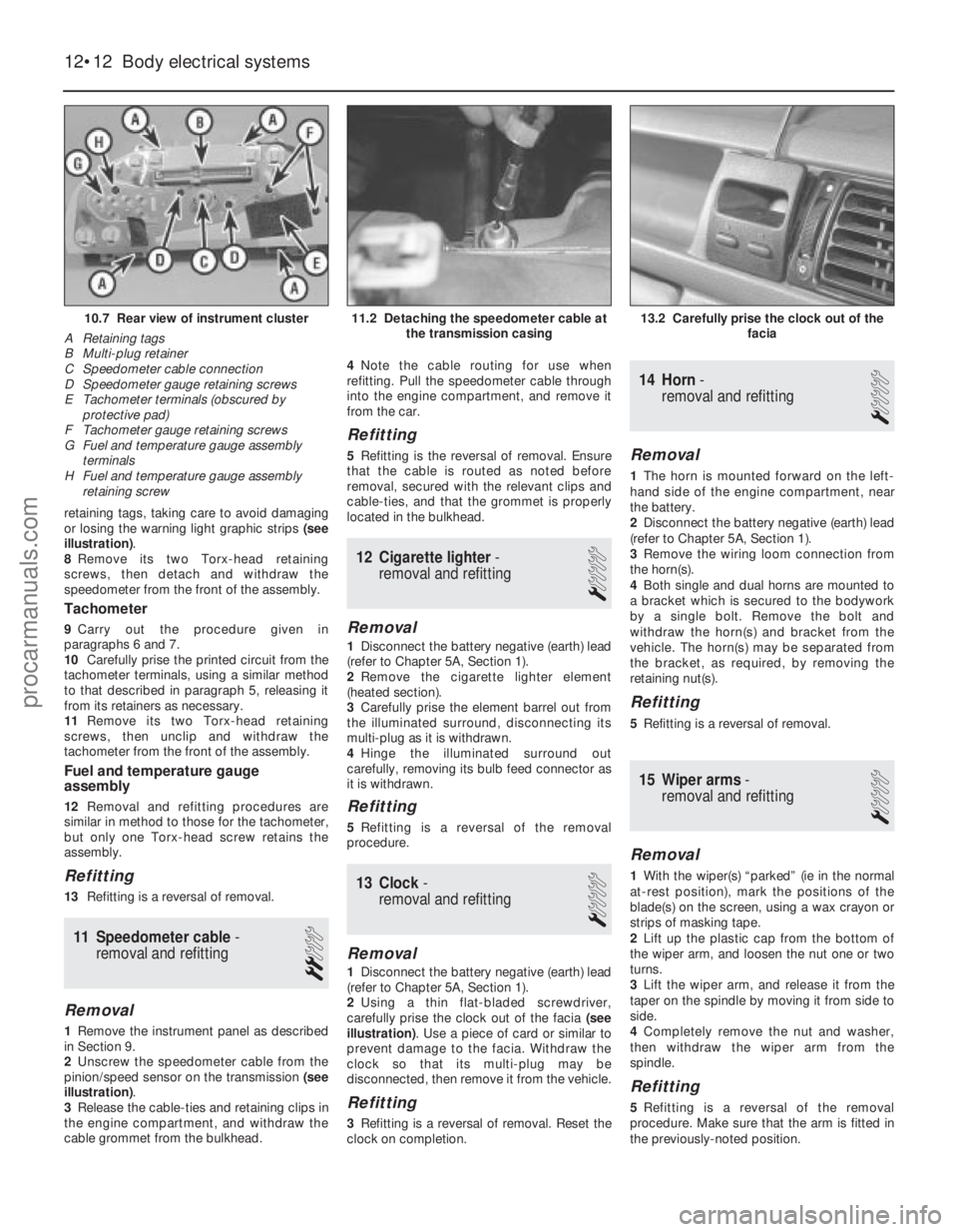
retaining tags, taking care to avoid damaging
or losing the warning light graphic strips (see
illustration) .
8 Remove its two Torx-head retaining
screws, then detach and withdraw the
speedometer from the front of the assembly.
Tachometer
9 Carry out the procedure given in
paragraphs 6 and 7.
10 Carefully prise the printed circuit from the
tachometer terminals, using a similar method
to that described in paragraph 5, releasing it
from its retainers as necessary.
11 Remove its two Torx-head retaining
screws, then unclip and withdraw the
tachometer from the front of the assembly.
Fuel and temperature gauge
assembly
12 Removal and refitting procedures are
similar in method to those for the tachometer,
but only one Torx-head screw retains the
assembly.
Refitting
13 Refitting is a reversal of removal.
11 Speedometer cable -
removal and refitting
2
Removal
1 Remove the instrument panel as described
in Section 9.
2 Unscrew the speedometer cable from the
pinion/speed sensor on the transmission (see
illustration) .
3 Release the cable-ties and retaining clips in
the engine compartment, and withdraw the
cable grommet from the bulkhead. 4
Note the cable routing for use when
refitting. Pull the speedometer cable through
into the engine compartment, and remove it
from the car.
Refitting
5 Refitting is the reversal of removal. Ensure
that the cable is routed as noted before
removal, secured with the relevant clips and
cable-ties, and that the grommet is properly
located in the bulkhead.
12 Cigarette lighter -
removal and refitting
1
Removal
1 Disconnect the battery negative (earth) lead
(refer to Chapter 5A, Section 1).
2 Remove the cigarette lighter element
(heated section).
3 Carefully prise the element barrel out from
the illuminated surround, disconnecting its
multi-plug as it is withdrawn.
4 Hinge the illuminated surround out
carefully, removing its bulb feed connector as
it is withdrawn.
Refitting
5 Refitting is a reversal of the removal
procedure.
13 Clock -
removal and refitting
1
Removal
1 Disconnect the battery negative (earth) lead
(refer to Chapter 5A, Section 1).
2 Using a thin flat-bladed screwdriver,
carefully prise the clock out of the facia (see
illustration) . Use a piece of card or similar to
prevent damage to the facia. Withdraw the
clock so that its multi-plug may be
disconnected, then remove it from the vehicle.
Refitting
3 Refitting is a reversal of removal. Reset the
clock on completion.
14 Horn -
removal and refitting
1
Removal
1 The horn is mounted forward on the left-
hand side of the engine compartment, near
the battery.
2 Disconnect the battery negative (earth) lead
(refer to Chapter 5A, Section 1).
3 Remove the wiring loom connection from
the horn(s).
4 Both single and dual horns are mounted to
a bracket which is secured to the bodywork
by a single bolt. Remove the bolt and
withdraw the horn(s) and bracket from the
vehicle. The horn(s) may be separated from
the bracket, as required, by removing the
retaining nut(s).
Refitting
5 Refitting is a reversal of removal.
15 Wiper arms -
removal and refitting
1
Removal
1 With the wiper(s) “parked” (ie in the normal
at-rest position), mark the positions of the
blade(s) on the screen, using a wax crayon or
strips of masking tape.
2 Lift up the plastic cap from the bottom of
the wiper arm, and loosen the nut one or two
turns.
3 Lift the wiper arm, and release it from the
taper on the spindle by moving it from side to
side.
4 Completely remove the nut and washer,
then withdraw the wiper arm from the
spindle.
Refitting
5 Refitting is a reversal of the removal
procedure. Make sure that the arm is fitted in
the previously-noted position.
12•12 Body electrical systems
13.2 Carefully prise the clock out of the facia11.2 Detaching the speedometer cable atthe transmission casing10.7 Rear view of instrument cluster
A Retaining tags
B Multi-plug retainer
C Speedometer cable connection
D Speedometer gauge retaining screws
E Tachometer terminals (obscured by protective pad)
F Tachometer gauge retaining screws
G Fuel and temperature gauge assembly
terminals
H Fuel and temperature gauge assembly retaining screw
1595Ford Fiesta Remakeprocarmanuals.com
http://vnx.su