1989 FORD FIESTA checking oil
[x] Cancel search: checking oilPage 11 of 296
filter; if the additional working clearance is
required, remove also the auxiliary drivebelt
cover.
7Being careful not to touch the hot exhaust
components, place the drain pan under the
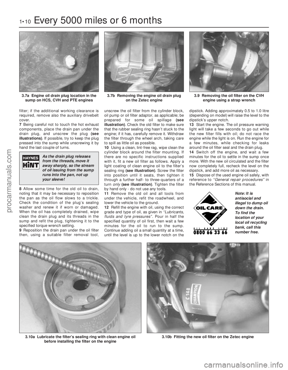
drain plug, and unscrew the plug (see
illustrations) . If possible, try to keep the plug
pressed into the sump while unscrewing it by
hand the last couple of turns.
8 Allow some time for the old oil to drain,
noting that it may be necessary to reposition
the pan as the oil flow slows to a trickle.
Check the condition of the plug’s sealing
washer and renew it if worn or damaged.
When the oil has completely drained, wipe
clean the drain plug and its threads in the
sump and refit the plug, tightening it to the
specified torque wrench setting.
9 Reposition the drain pan under the oil filter
then, using a suitable filter removal tool, unscrew the oil filter from the cylinder block,
oil pump or oil filter adaptor, as applicable; be
prepared for some oil spillage
(see
illustration) . Check the old filter to make sure
that the rubber sealing ring hasn’t stuck to the
engine; if it has, carefully remove it. Withdraw
the filter through the wheel arch, taking care
to spill as little oil as possible.
10 Using a clean, lint-free rag, wipe clean the
cylinder block around the filter mounting. If
there are no specific instructions supplied
with it, fit a new oil filter as follows. Apply a
light coating of clean engine oil to the filter’s
sealing ring (see illustration) . Screw the filter
into position until it seats, then tighten it
through a further half- to three-quarters of a
turn only (see illustration) . Tighten the filter
by hand only - do not use any tools.
11 Remove the old oil and all tools from
under the vehicle, refit the roadwheel, and
lower the vehicle to the ground.
12 Refill the engine with oil, using the correct
grade and type of oil, as given in “Lubricants,
fluids and tyre pressures” . Pour in half the
specified quantity of oil first, then wait a few
minutes for the oil to run to the sump.
Continue adding oil a small quantity at a time,
until the level is up to the lower notch on the dipstick. Adding approximately 0.5 to 1.0 litre
(depending on model) will raise the level to the
dipstick’s upper notch.
13
Start the engine. The oil pressure warning
light will take a few seconds to go out while
the new filter fills with oil; do not race the
engine while the light is on. Run the engine for
a few minutes, while checking for leaks
around the oil filter seal and the drain plug.
14 Switch off the engine, and wait a few
minutes for the oil to settle in the sump once
more. With the new oil circulated and the filter
now completely full, recheck the level on the
dipstick, and add more oil as necessary.
15 Dispose of the used engine oil safely, with
reference to “General repair procedures” in
the Reference Sections of this manual.
1•10Every 5000 miles or 6 months
3.10b Fitting the new oil filter on the Zetec engine 3.10a Lubricate the filter’s sealing ring with clean engine oil before installing the filter on the engine
3.9 Removing the oil filter on the CVHengine using a strap wrench3.7b Removing the engine oil drain plug on the Zetec engine3.7a Engine oil drain plug location in thesump on HCS, CVH and PTE engines
1595Ford Fiesta Remake
Note: It is
antisocial and
illegal to dump oil
down the drain.
To find the
location of your
local oil recycling
bank, call this
number free.
As the drain plug releases
from the threads, move it
away sharply, so the stream
of oil issuing from the sump
runs into the pan, not up
your sleeve!
procarmanuals.com
http://vnx.su
Page 14 of 296
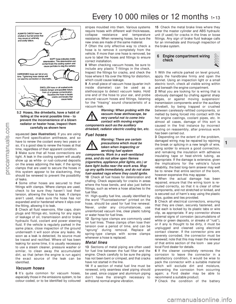
squeezed (see illustration) . If you are using
non-Ford specification antifreeze, and so
have to renew the coolant every two years or
so, it’s a good idea to renew the hoses at that
time, regardless of their apparent condition.
3 Make sure that all hose connections are
tight. A leak in the cooling system will usually
show up as white- or rust-coloured deposits
on the areas adjoining the leak; if the spring
clamps that are used to secure the hoses in
this system appear to be slackening, they
should be renewed to prevent the possibility
of leaks.
4 Some other hoses are secured to their
fittings with clamps. Where clamps are used,
check to be sure they haven’t lost their
tension, allowing the hose to leak. If clamps
aren’t used, make sure the hose has not
expanded and/or hardened where it slips over
the fitting, allowing it to leak.
5 Check all fluid reservoirs, filler caps, drain
plugs and fittings etc, looking for any signs
of leakage of oil, transmission and/or brake
hydraulic fluid, coolant and power steering
fluid. If the vehicle is regularly parked in the
same place, close inspection of the ground
underneath it will soon show any leaks. As
soon as a leak is detected, its source must
be traced and rectified. Where oil has been
leaking for some time, it is usually necessary
to use a steam cleaner, pressure washer or
similar, to clean away the accumulated
dirt, so that (when the engine is run again)
the exact source of the leak can be
identified.
Vacuum hoses
6 It’s quite common for vacuum hoses,
especially those in the emissions system, to be
colour-coded, or to be identified by coloured stripes moulded into them. Various systems
require hoses with different wall thicknesses,
collapse resistance and temperature
resistance. When renewing hoses, be sure the
new ones are made of the same material.
7
Often the only effective way to check a
hose is to remove it completely from the
vehicle. If more than one hose is removed, be
sure to label the hoses and fittings to ensure
correct installation.
8 When checking vacuum hoses, be sure to
include any plastic T-fittings in the check.
Inspect the fittings for cracks, and check the
hose where it fits over the fitting for distortion,
which could cause leakage.
9 A small piece of vacuum hose (quarter-inch
inside diameter) can be used as a
stethoscope to detect vacuum leaks. Hold
one end of the hose to your ear, and probe
around vacuum hoses and fittings, listening
for the “hissing” sound characteristic of a
vacuum leak. Warning: When probing with the
vacuum-hose stethoscope, be
very careful not to come into
contact with moving engine
components such as the auxiliary
drivebelt, radiator electric cooling fan, etc.
Fuel hoses
Warning: There are certain
precautions which must be
taken when inspecting or
servicing fuel system
components. Work in a well-ventilated
area, and do not allow open flames
(cigarettes, appliance pilot lights, etc.) or
bare light bulbs near the work area. Mop
up any spills immediately, and do not store
fuel-soaked rags where they could ignite.
10 Check all fuel hoses for deterioration and
chafing. Check especially for cracks in areas
where the hose bends, and also just before
fittings, such as where a hose attaches to the
fuel filter.
11 High-quality fuel line, usually identified by
the word “Fluoroelastomer” printed on the
hose, should be used for fuel line renewal.
Never, under any circumstances, use
unreinforced vacuum line, clear plastic tubing
or water hose for fuel lines.
12 Spring- type clamps are commonly used
on fuel lines. These clamps often lose their
tension over a period of time, and can be
“sprung” during removal. Replace all
spring- type clamps with screw clamps
whenever a hose is replaced.
Metal lines
13 Sections of metal piping are often used
for fuel line between the fuel filter and the
engine. Check carefully to be sure the piping
has not been bent or crimped, and that cracks
have not started in the line.
14 If a section of metal fuel line must be
renewed, only seamless steel piping should
be used, since copper and aluminium piping
don’t have the strength necessary to
withstand normal engine vibration. 15
Check the metal brake lines where they
enter the master cylinder and ABS hydraulic
unit (if used) for cracks in the lines or loose
fittings. Any sign of brake fluid leakage calls
for an immediate and thorough inspection of
the brake system.
6 Engine compartment wiring check
1
1With the vehicle parked on level ground,
apply the handbrake firmly and open the
bonnet. Using an inspection light or a small
electric torch, check all visible wiring within
and beneath the engine compartment.
2 What you are looking for is wiring that is
obviously damaged by chafing against sharp
edges, or against moving suspension/
transmission components and/or the auxiliary
drivebelt, by being trapped or crushed
between carelessly-refitted components, or
melted by being forced into contact with the
hot engine castings, coolant pipes, etc. In
almost all cases, damage of this sort is
caused in the first instance by incorrect
routing on reassembly, after previous work
has been carried out.
3 Depending on the extent of the problem,
damaged wiring may be repaired by rejoining
the break or splicing-in a new length of wire,
using solder to ensure a good connection,
and remaking the insulation with adhesive
insulating tape or heat-shrink tubing, as
appropriate. If the damage is extensive, given
the implications for the vehicle’s future
reliability, the best long-term answer may well
be to renew that entire section of the loom,
however expensive this may appear.
4 When the actual damage has been
repaired, ensure that the wiring loom is re-
routed correctly, so that it is clear of other
components, and not stretched or kinked, and
is secured out of harm’s way using the plastic
clips, guides and ties provided.
5 Check all electrical connectors, ensuring
that they are clean, securely fastened, and
that each is locked by its plastic tabs or wire
clip, as appropriate. If any connector shows
external signs of corrosion (accumulations of
white or green deposits, or streaks of “rust”),
or if any is thought to be dirty, it must be
unplugged and cleaned using electrical
contact cleaner. If the connector pins are
severely corroded, the connector must be
renewed; note that this may mean the renewal
of that entire section of the loom - see your
local Ford dealer for details.
6 If the cleaner completely removes the
corrosion to leave the connector in a
satisfactory condition, it would be wise to
pack the connector with a suitable material
which will exclude dirt and moisture,
preventing the corrosion from occurring
again; a Ford dealer may be able to
recommend a suitable product.
7 Check the condition of the battery
Every 10 000 miles or 12 months1•13
5.2 Hoses, like drivebelts, have a habit of
failing at the worst possible time - to
prevent the inconvenience of a blown radiator or heater hose, inspect them
carefully as shown here
1
1595Ford Fiesta Remakeprocarmanuals.com
http://vnx.su
Page 19 of 296
3Check that the roadwheel nuts are tightened
to the specified torque wrench setting.
4 Refit the wheel covers.
16 Door, tailgate and bonnet
check and lubrication
1
1Check that the doors and tailgate/boot lid
close securely. Check that the bonnet safety
catch operates correctly. Check the operation
of the door check straps.
2 Lubricate the hinges, door check straps,
the striker plates and the bonnet catch
sparingly with a little oil or grease.
17 Seat belt check
1
1 Check the seat belts for satisfactory
operation and condition. Inspect the webbing
for fraying and cuts. Check that they retract
smoothly and without binding into their reels.
2 Check that the seat belt mounting bolts are
tight, and if necessary tighten them to the
specified torque wrench settings as given in
Chapter 11.
18 Bodywork, paint and exterior trim check
1
1The best time to carry out this check is after
the car has been washed so that any surface
blemish or scratch will be clearly evident and
not hidden by a film of dirt.
2 Starting at one front corner check the
paintwork all around the car, looking for minor
scratches or more serious dents. Check all
the trim and make sure that it is securely
attached over its entire length.
3 Check the security of all door locks, door
mirrors, badges, bumpers, front grille and
wheel trim. Anything found loose, or in need of
further attention should be done with reference
to the relevant Chapters of this manual.
4 Rectify any problems noticed with the
paintwork or body panels as described in
Chapter 11.
19 Road test
1
Check the operation and
performance of the braking
system
1 Make sure that the vehicle does not pull to
one side when braking, and that the wheels
do not lock prematurely when braking hard.
2 Check that there is no vibration through the
steering when braking. 3
Check that the handbrake operates
correctly, without excessive movement of the
lever, and that it holds the vehicle stationary
on a slope.
4 Test the operation of the brake servo unit
as follows. With the engine switched off,
depress the footbrake four or five times to
exhaust the vacuum, then hold the pedal
depressed. Start the engine, and there should
be a noticeable “give” in the brake pedal as
vacuum builds up. Allow the engine to run for
at least two minutes, and then switch it off. If
the brake pedal is depressed again, it should
be possible to detect a hiss from the servo as
the pedal is depressed. After about four or five
applications, no further hissing should be
heard, and the pedal should feel considerably
firmer.
Steering and suspension
5 Check for any abnormalities in the steering,
suspension, handling or road “feel”.
6 Drive the vehicle, and check that there are
no unusual vibrations or noises.
7 Check that the steering feels positive, with
no excessive sloppiness or roughness, and
check for any suspension noises when
cornering and driving over bumps.
Drivetrain
8 Check the performance of the engine,
transmission and driveshafts.
9 Check that the engine starts correctly, both
when cold and when hot.
10 Listen for any unusual noises from the
engine and transmission.
11 Make sure that the engine runs smoothly
when idling, and that there is no hesitation
when accelerating.
12 On manual transmission models, check
that all gears can be engaged smoothly
without noise, and that the gear lever action is
not abnormally vague or “notchy”.
13 On automatic transmission models, make
sure that the drive seems smooth without
jerks or engine speed “flare-ups”. Check that
all the gear positions can be selected with the
vehicle at rest. If any problems are found, they
should be referred to a Ford dealer.
14 Listen for a metallic clicking sound from
the front of the vehicle, as the vehicle is driven
slowly in a circle with the steering on full-lock.
Carry out this check in both directions. If a
clicking noise is heard, this indicates wear in a
driveshaft joint, in which case renew the joint
if necessary.
Clutch
15 Check that the clutch pedal moves
smoothly and easily through its full travel, and
that the clutch itself functions correctly, with
no trace of slip or drag. If the movement is
uneven or stiff in places, check that the cable
is routed correctly, with no sharp turns.
16 Inspect both ends of the clutch inner
cable, both at the transmission end and inside
the car, for signs of wear and fraying.
Instruments and electrical
equipment
17 Check the operation of all instruments
and electrical equipment.
18 Make sure that all instruments read
correctly, and switch on all electrical equipment
in turn, to check that it functions properly.
20 Automatic transmission fluid level check
1
1The level of the automatic transmission fluid
should be carefully maintained. Low fluid level
can lead to slipping or loss of drive, while
overfilling can cause foaming, loss of fluid and
transmission damage.
2 The transmission fluid level should only be
checked when the transmission is hot (at its
normal operating temperature). If the vehicle
has just been driven over 10 miles (15 miles in
a cold climate), and the fluid temperature is 60
to 70ºC, the transmission is hot.
Caution: If the vehicle has just been driven
for a long time at high speed or in city
traffic in hot weather, or if it has been
pulling a trailer, an accurate fluid level
reading cannot be obtained. In these
circumstances, allow the fluid to cool
down for about 30 minutes.
3 Park the vehicle on level ground, apply the
handbrake, and start the engine. While the
engine is idling, depress the brake pedal and
move the selector lever through all the gear
positions three times, beginning and ending in
“P”.
4 Allow the engine to idle for one minute, then
(with the engine still idling) remove the
dipstick from its tube. Note the condition and
colour of the fluid on the dipstick.
5 Wipe the fluid from the dipstick with a clean
rag, and re-insert it into the filler tube until the
cap seats.
6 Pull the dipstick out again, and note the
fluid level. The level should be between
the “MIN” and “MAX” marks. If the level is
on the “MIN” mark, stop the engine, and add
the specified automatic transmission fluid
through the dipstick tube, using a clean funnel
if necessary. It is important not to introduce
dirt into the transmission when topping-up.
7 Add the fluid a little at a time, and keep
checking the level as previously described
until it is correct. The difference between the
“MIN” and “MAX” marks on the dipstick is
approximately 0.4 litres.
8 The need for regular topping-up of the
transmission fluid indicates a leak, which
should be found and rectified without delay.
9 The condition of the fluid should also be
checked along with the level. If the fluid on the
dipstick is black or a dark reddish-brown
colour, or if it has a burned smell, the fluid
should be changed. If you are in doubt about
the condition of the fluid, purchase some new
fluid, and compare the two for colour and smell.
1•18Every 10 000 miles or 12 months
1595Ford Fiesta Remakeprocarmanuals.com
http://vnx.su
Page 20 of 296
21 Spark plug renewal and HTcomponent check
1
Note: Spark plug renewal at this service
interval is only necessary on the HCS, CVH
and PTE engines. On Zetec engines, the
recommended interval for spark plug renewal
is every 30 000 miles or three years.
Spark plug check and renewal
1 It is vital for the correct running, full
performance and proper economy of the engine
that the spark plugs perform with maximum
efficiency. The most important factor in ensuring
this is that the plugs fitted are appropriate for the
engine. The suitable type is given in the
Specifications Section at the beginning of this
Chapter, on the Vehicle Emissions Control
Information (VECI) label located on the
underside of the bonnet (only on models sold in
some areas) or in the vehicle’s Owner’s
Handbook. If the correct type is used and the
engine is in good condition, the spark plugs
should not need attention between scheduled
renewal intervals. Spark plug cleaning is rarely
necessary, and should not be attempted unless
specialised equipment is available, as damage
can easily be caused to the firing ends.
2 Spark plug removal and refitting requires a
spark plug socket, with an extension which can
be turned by a ratchet handle or similar. This
socket is lined with a rubber sleeve, to protect
the porcelain insulator of the spark plug, and to
hold the plug while you insert it into the spark
plug hole. You will also need a set of feeler
gauges, to check the spark plug electrode gap,
and a torque wrench to tighten the new plugs
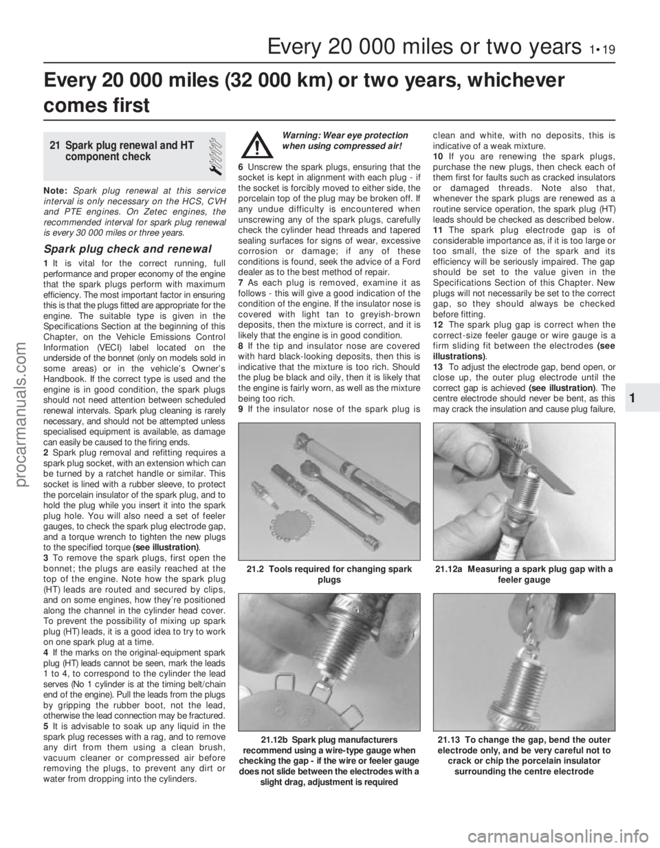
to the specified torque (see illustration).
3 To remove the spark plugs, first open the
bonnet; the plugs are easily reached at the
top of the engine. Note how the spark plug
(HT) leads are routed and secured by clips,
and on some engines, how they’re positioned
along the channel in the cylinder head cover.
To prevent the possibility of mixing up spark
plug (HT) leads, it is a good idea to try to work
on one spark plug at a time.
4 If the marks on the original-equipment spark
plug (HT) leads cannot be seen, mark the leads
1 to 4, to correspond to the cylinder the lead
serves (No 1 cylinder is at the timing belt/chain
end of the engine). Pull the leads from the plugs
by gripping the rubber boot, not the lead,
otherwise the lead connection may be fractured.
5 It is advisable to soak up any liquid in the
spark plug recesses with a rag, and to remove
any dirt from them using a clean brush,
vacuum cleaner or compressed air before
removing the plugs, to prevent any dirt or
water from dropping into the cylinders. Warning: Wear eye protection
when using compressed air!
6 Unscrew the spark plugs, ensuring that the
socket is kept in alignment with each plug - if
the socket is forcibly moved to either side, the
porcelain top of the plug may be broken off. If
any undue difficulty is encountered when
unscrewing any of the spark plugs, carefully
check the cylinder head threads and tapered
sealing surfaces for signs of wear, excessive
corrosion or damage; if any of these
conditions is found, seek the advice of a Ford
dealer as to the best method of repair.
7 As each plug is removed, examine it as
follows - this will give a good indication of the
condition of the engine. If the insulator nose is
covered with light tan to greyish-brown
deposits, then the mixture is correct, and it is
likely that the engine is in good condition.
8 If the tip and insulator nose are covered
with hard black-looking deposits, then this is
indicative that the mixture is too rich. Should
the plug be black and oily, then it is likely that
the engine is fairly worn, as well as the mixture
being too rich.
9 If the insulator nose of the spark plug is clean and white, with no deposits, this is
indicative of a weak mixture.
10
If you are renewing the spark plugs,
purchase the new plugs, then check each of
them first for faults such as cracked insulators
or damaged threads. Note also that,
whenever the spark plugs are renewed as a
routine service operation, the spark plug (HT)
leads should be checked as described below.
11 The spark plug electrode gap is of
considerable importance as, if it is too large or
too small, the size of the spark and its
efficiency will be seriously impaired. The gap
should be set to the value given in the
Specifications Section of this Chapter. New
plugs will not necessarily be set to the correct
gap, so they should always be checked
before fitting.
12 The spark plug gap is correct when the
correct-size feeler gauge or wire gauge is a
firm sliding fit between the electrodes (see
illustrations) .
13 To adjust the electrode gap, bend open, or
close up, the outer plug electrode until the
correct gap is achieved (see illustration). The
centre electrode should never be bent, as this
may crack the insulation and cause plug failure,
Every 20 000 miles (32 000 km) or two years, whichever
comes first
Every 20 000 miles or two years1•19
21.12b Spark plug manufacturers
recommend using a wire-type gauge when
checking the gap - if the wire or feeler gauge
does not slide between the electrodes with a slight drag, adjustment is required
21.12a Measuring a spark plug gap with a feeler gauge21.2 Tools required for changing spark plugs
21.13 To change the gap, bend the outer
electrode only, and be very careful not to crack or chip the porcelain insulator
surrounding the centre electrode
1
1595Ford Fiesta Remakeprocarmanuals.com
http://vnx.su
Page 21 of 296
if nothing worse. If the outer electrode is not
exactly over the centre electrode, bend it gently
to align them. Special spark plug gap adjusting
tools are available from motor accessory shops,
or from certain spark plug manufacturers.
14Before fitting the spark plugs, check that
the threaded connector sleeves at the top of
the plugs are tight, and that the plug exterior
surfaces and threads are clean. Brown
staining on the porcelain, immediately above
the metal body, is quite normal, and does not
necessarily indicate a “leak” between the
body and insulator.
15 Apply a smear of copper-based grease or
anti-seize compound to the threads of each
plug, and screw them in by hand where
possible. Take extra care to enter the plug
threads correctly, as the cylinder head is of
aluminium alloy.
16 When each spark plug is started correctly
on its threads, screw it down until it just seats
lightly, then tighten it to the specified torque
wrench setting. If a torque wrench is not
available - and this is one case where the use of
a torque wrench is strongly recommended -
tighten each spark plug through no more than
1/4 of a turn (CVH and PTE engines) or 1/16 of a
turn (HCS and Zetec engines) after it seats. HCS
and Zetec engines are fitted with taper-seat
spark plugs, identifiable by not having a sealing
washer, and these in particular should NEVER
be overtightened - their tapered seats mean
they are almost impossible to remove if abused.
17 Reconnect the spark plug (HT) leads in
their correct order, using a twisting motion on
the boot until it is firmly seated on the end of
the spark plug and on the cylinder head cover.
Spark plug (HT) lead, distributor
cap and rotor arm check
18 The spark plug (HT) leads should be
checked whenever the plugs themselves are renewed. Start by making a visual check of
the leads while the engine is running. In a
darkened garage (make sure there is
ventilation) start the engine and observe each
lead. Be careful not to come into contact with
any moving engine parts. If there is a break in
the lead, you will see arcing or a small spark
at the damaged area.
19
The spark plug (HT) leads should be
inspected one at a time, to prevent mixing up
the firing order, which is essential for proper
engine operation. Each original lead should
be numbered to identify its cylinder. If the
number is illegible, a piece of tape can be
marked with the correct number, and
wrapped around the lead (the leads should be
numbered 1 to 4, with No 1 lead nearest the
timing belt end of the engine). The lead can
then be disconnected.
20 Check inside the boot for corrosion, which
will look like a white crusty powder. Clean this
off as much as possible; if it is excessive, or if
cleaning leaves the metal connector too badly
eroded to be fit for further use, the lead must
be renewed. Push the lead and boot back
onto the end of the spark plug. The boot
should fit tightly onto the end of the plug - if it
doesn’t, remove the lead and use pliers
carefully to crimp the metal connector inside
the boot until the fit is snug.
21 Using a clean rag, wipe the entire length
of the lead to remove built-up dirt and grease. Once the lead is clean, check for burns,
cracks and other damage. Do not bend the
lead sharply, because the conductor might
break.
22 Disconnect the lead from the ignition coil
by pressing together the plastic retaining
catches (where fitted) and pulling the end
fitting off the coil terminal. Check for corrosion
and for a tight fit. If a meter with the correct
measuring range is available, measure the
resistance of the disconnected lead from its
coil connector to its spark plug connector. If
the resistance recorded for any of the leads
exceeds the value specified, all the leads
should be renewed as a set. Refit the lead to
the coil, noting that each coil terminal is
marked with its respective cylinder number,
so that there is no risk of mixing up the leads
and upsetting the firing order.
23 Inspect the remaining spark plug (HT)
leads, ensuring that each is securely fastened
at the distributor cap or ignition coil and spark
plug when the check is complete. If any sign
of arcing, severe connector corrosion, burns,
cracks or other damage is noticed, obtain new
spark plug (HT) leads, renewing them as a set.
If new spark plug leads are to be fitted,
remove and refit them one at a time, to avoid
mix-ups in the firing order. 24
On models with distributor ignition
systems, refer to Chapter 5B and remove the
distributor cap then thoroughly clean it inside
and out with a dry lint-free rag.
25 Examine the HT lead segments inside the
cap. If they appear badly burned or pitted
renew the cap. Also check the carbon brush
in the centre of the cap, ensuring that it is free
to move and stands proud of its holder. Make
sure that there are no sign of cracks or black
“tracking” lines running down the inside of the
cap, which will also mean renewal if evident.
26 Inspect the rotor arm checking it for
security and also for signs of deterioration as
described above.
27 Refit the cap as described in Chapter 5B
on completion.
22 Idle speed control valve cleaning and maintenance
1
Note: The idle speed control valve may be
mounted on the air cleaner, on the engine
compartment bulkhead, or on the side of the inlet
manifold according to valve make and year of
manufacture. Valves manufactured by Weber are
mounted on the air cleaner and only these valves
require the periodic maintenance described
below. Bulkhead and inlet manifold mounted
valves are manufactured by Hitachi and are
maintenance free. Refer to the warning note in
Section 1 of Chapter 4C before proceeding.
1 Remove the valve as described in Chap-
ter 4C, Section 14.
2 Immerse the valve head in a suitable
container filled with clean petrol, and allow it
to soak for approximately three minutes.
3 Clean the valve bore, slots and piston with
petrol, using a suitable lint-free cloth, then
gently move the piston up and down in its
bore using a small screwdriver (see
illustration) . Ensure that no cloth particles
enter the bore, and do not use the slots to
move the piston.
4 Rinse the valve again with clean petrol, then
dry it using an air line (or other source of
compressed air).
Warning: Wear eye protection
when using compressed air!
5 Clean the mating faces of the valve and the
air filter housing then refit as described in
Chapter 4C, Section 14.
1•20Every 20 000 miles or two years
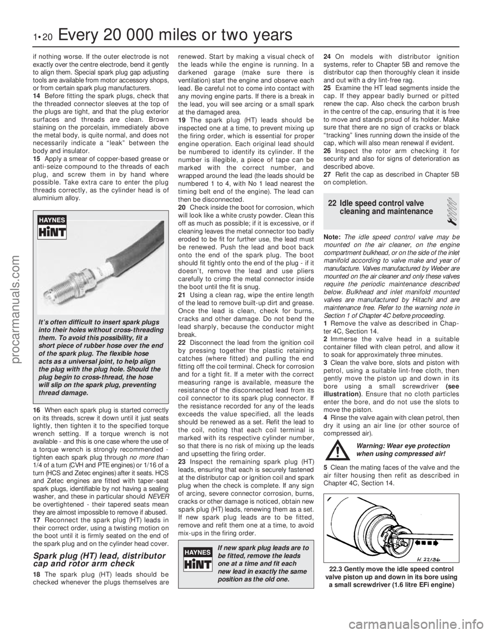
22.3 Gently move the idle speed control
valve piston up and down in its bore using
a small screwdriver (1.6 litre EFi engine)
1595Ford Fiesta Remake
It’s often difficult to insert spark plugs
into their holes without cross-threading
them. To avoid this possibility, fit a
short piece of rubber hose over the end
of the spark plug. The flexible hose
acts as a universal joint, to help align
the plug with the plug hole. Should the
plug begin to cross-thread, the hose
will slip on the spark plug, preventing
thread damage.
If new spark plug leads are tobe fitted, remove the leads
one at a time and fit each
new lead in exactly the same
position as the old one.
procarmanuals.com
http://vnx.su
Page 24 of 296
SEFi fuel injection models
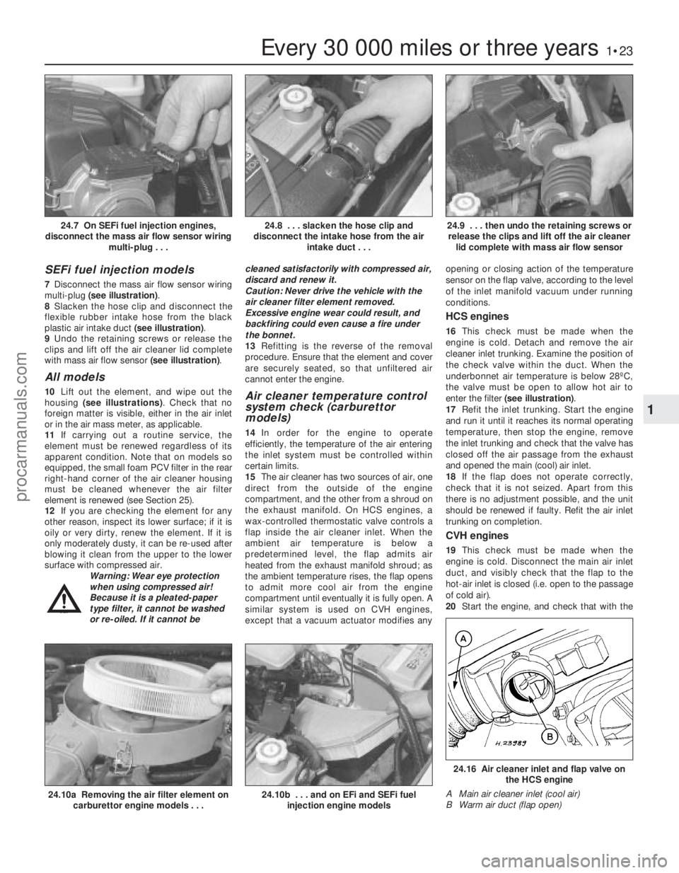
7Disconnect the mass air flow sensor wiring
multi-plug (see illustration) .
8 Slacken the hose clip and disconnect the
flexible rubber intake hose from the black
plastic air intake duct (see illustration).
9 Undo the retaining screws or release the
clips and lift off the air cleaner lid complete
with mass air flow sensor (see illustration).
All models
10Lift out the element, and wipe out the
housing (see illustrations) . Check that no
foreign matter is visible, either in the air inlet
or in the air mass meter, as applicable.
11 If carrying out a routine service, the
element must be renewed regardless of its
apparent condition. Note that on models so
equipped, the small foam PCV filter in the rear
right-hand corner of the air cleaner housing
must be cleaned whenever the air filter
element is renewed (see Section 25).
12 If you are checking the element for any
other reason, inspect its lower surface; if it is
oily or very dirty, renew the element. If it is
only moderately dusty, it can be re-used after
blowing it clean from the upper to the lower
surface with compressed air. Warning: Wear eye protection
when using compressed air!
Because it is a pleated-paper
type filter, it cannot be washed
or re-oiled. If it cannot be cleaned satisfactorily with compressed air,
discard and renew it.
Caution: Never drive the vehicle with the
air cleaner filter element removed.
Excessive engine wear could result, and
backfiring could even cause a fire under
the bonnet.
13
Refitting is the reverse of the removal
procedure. Ensure that the element and cover
are securely seated, so that unfiltered air
cannot enter the engine.Air cleaner temperature control
system check (carburettor
models)
14 In order for the engine to operate
efficiently, the temperature of the air entering
the inlet system must be controlled within
certain limits.
15 The air cleaner has two sources of air, one
direct from the outside of the engine
compartment, and the other from a shroud on
the exhaust manifold. On HCS engines, a
wax-controlled thermostatic valve controls a
flap inside the air cleaner inlet. When the
ambient air temperature is below a
predetermined level, the flap admits air
heated from the exhaust manifold shroud; as
the ambient temperature rises, the flap opens
to admit more cool air from the engine
compartment until eventually it is fully open. A
similar system is used on CVH engines,
except that a vacuum actuator modifies any opening or closing action of the temperature
sensor on the flap valve, according to the level
of the inlet manifold vacuum under running
conditions.
HCS engines
16
This check must be made when the
engine is cold. Detach and remove the air
cleaner inlet trunking. Examine the position of
the check valve within the duct. When the
underbonnet air temperature is below 28ºC,
the valve must be open to allow hot air to
enter the filter (see illustration) .
17 Refit the inlet trunking. Start the engine
and run it until it reaches its normal operating
temperature, then stop the engine, remove
the inlet trunking and check that the valve has
closed off the air passage from the exhaust
and opened the main (cool) air inlet.
18 If the flap does not operate correctly,
check that it is not seized. Apart from this
there is no adjustment possible, and the unit
should be renewed if faulty. Refit the air inlet
trunking on completion.
CVH engines
19 This check must be made when the
engine is cold. Disconnect the main air inlet
duct, and visibly check that the flap to the
hot-air inlet is closed (i.e. open to the passage
of cold air).
20 Start the engine, and check that with the
Every 30 000 miles or three years1•23
24.9 . . . then undo the retaining screws or
release the clips and lift off the air cleaner lid complete with mass air flow sensor24.8 . . . slacken the hose clip and
disconnect the intake hose from the air intake duct . . .24.7 On SEFi fuel injection engines,
disconnect the mass air flow sensor wiring multi-plug . . .
24.16 Air cleaner inlet and flap valve onthe HCS engine
A Main air cleaner inlet (cool air)
B Warm air duct (flap open)
24.10b . . . and on EFi and SEFi fuel injection engine models24.10a Removing the air filter element oncarburettor engine models . . .
1
1595Ford Fiesta Remakeprocarmanuals.com
http://vnx.su
Page 25 of 296
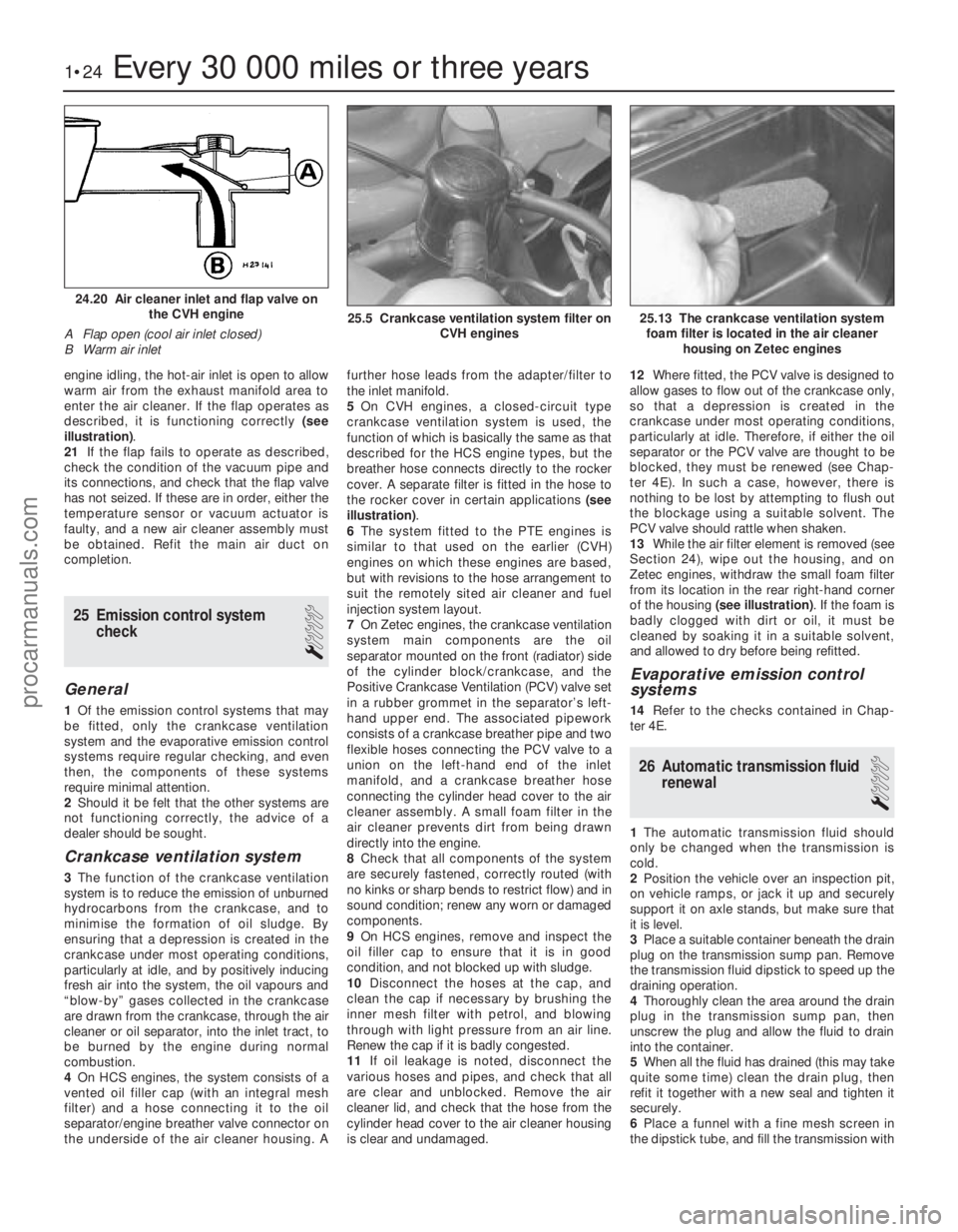
engine idling, the hot-air inlet is open to allow
warm air from the exhaust manifold area to
enter the air cleaner. If the flap operates as
described, it is functioning correctly (see
illustration) .
21 If the flap fails to operate as described,
check the condition of the vacuum pipe and
its connections, and check that the flap valve
has not seized. If these are in order, either the
temperature sensor or vacuum actuator is
faulty, and a new air cleaner assembly must
be obtained. Refit the main air duct on
completion.
25 Emission control system
check
1
General
1Of the emission control systems that may
be fitted, only the crankcase ventilation
system and the evaporative emission control
systems require regular checking, and even
then, the components of these systems
require minimal attention.
2 Should it be felt that the other systems are
not functioning correctly, the advice of a
dealer should be sought.
Crankcase ventilation system
3 The function of the crankcase ventilation
system is to reduce the emission of unburned
hydrocarbons from the crankcase, and to
minimise the formation of oil sludge. By
ensuring that a depression is created in the
crankcase under most operating conditions,
particularly at idle, and by positively inducing
fresh air into the system, the oil vapours and
“blow-by” gases collected in the crankcase
are drawn from the crankcase, through the air
cleaner or oil separator, into the inlet tract, to
be burned by the engine during normal
combustion.
4 On HCS engines, the system consists of a
vented oil filler cap (with an integral mesh
filter) and a hose connecting it to the oil
separator/engine breather valve connector on
the underside of the air cleaner housing. A further hose leads from the adapter/filter to
the inlet manifold.
5
On CVH engines, a closed-circuit type
crankcase ventilation system is used, the
function of which is basically the same as that
described for the HCS engine types, but the
breather hose connects directly to the rocker
cover. A separate filter is fitted in the hose to
the rocker cover in certain applications (see
illustration) .
6 The system fitted to the PTE engines is
similar to that used on the earlier (CVH)
engines on which these engines are based,
but with revisions to the hose arrangement to
suit the remotely sited air cleaner and fuel
injection system layout.
7 On Zetec engines, the crankcase ventilation
system main components are the oil
separator mounted on the front (radiator) side
of the cylinder block/crankcase, and the
Positive Crankcase Ventilation (PCV) valve set
in a rubber grommet in the separator’s left-
hand upper end. The associated pipework
consists of a crankcase breather pipe and two
flexible hoses connecting the PCV valve to a
union on the left-hand end of the inlet
manifold, and a crankcase breather hose
connecting the cylinder head cover to the air
cleaner assembly. A small foam filter in the
air cleaner prevents dirt from being drawn
directly into the engine.
8 Check that all components of the system
are securely fastened, correctly routed (with
no kinks or sharp bends to restrict flow) and in
sound condition; renew any worn or damaged
components.
9 On HCS engines, remove and inspect the
oil filler cap to ensure that it is in good
condition, and not blocked up with sludge.
10 Disconnect the hoses at the cap, and
clean the cap if necessary by brushing the
inner mesh filter with petrol, and blowing
through with light pressure from an air line.
Renew the cap if it is badly congested.
11 If oil leakage is noted, disconnect the
various hoses and pipes, and check that all
are clear and unblocked. Remove the air
cleaner lid, and check that the hose from the
cylinder head cover to the air cleaner housing
is clear and undamaged. 12
Where fitted, the PCV valve is designed to
allow gases to flow out of the crankcase only,
so that a depression is created in the
crankcase under most operating conditions,
particularly at idle. Therefore, if either the oil
separator or the PCV valve are thought to be
blocked, they must be renewed (see Chap-
ter 4E). In such a case, however, there is
nothing to be lost by attempting to flush out
the blockage using a suitable solvent. The
PCV valve should rattle when shaken.
13 While the air filter element is removed (see
Section 24), wipe out the housing, and on
Zetec engines, withdraw the small foam filter
from its location in the rear right-hand corner
of the housing (see illustration) . If the foam is
badly clogged with dirt or oil, it must be
cleaned by soaking it in a suitable solvent,
and allowed to dry before being refitted.
Evaporative emission control
systems
14 Refer to the checks contained in Chap-
ter 4E.
26 Automatic transmission fluid renewal
1
1The automatic transmission fluid should
only be changed when the transmission is
cold.
2 Position the vehicle over an inspection pit,
on vehicle ramps, or jack it up and securely
support it on axle stands, but make sure that
it is level.
3 Place a suitable container beneath the drain
plug on the transmission sump pan. Remove
the transmission fluid dipstick to speed up the
draining operation.
4 Thoroughly clean the area around the drain
plug in the transmission sump pan, then
unscrew the plug and allow the fluid to drain
into the container.
5 When all the fluid has drained (this may take
quite some time) clean the drain plug, then
refit it together with a new seal and tighten it
securely.
6 Place a funnel with a fine mesh screen in
the dipstick tube, and fill the transmission with
1•24Every 30 000 miles or three years
25.13 The crankcase ventilation system foam filter is located in the air cleaner housing on Zetec engines25.5 Crankcase ventilation system filter on CVH engines
24.20 Air cleaner inlet and flap valve onthe CVH engine
A Flap open (cool air inlet closed)
B Warm air inlet
1595Ford Fiesta Remakeprocarmanuals.com
http://vnx.su
Page 28 of 296

2A
1595Ford Fiesta Remake
General
Engine type . . . . . . . . . . . . . . . . . . . . . . . . . . . . . . . . . . . .\
. . . . . . . . . . . Four-cylinder, in-line overhead valve
Engine code:1.0 litre carburettor models . . . . . . . . . . . . . . . . . . . . . . . . . . . . . . . . . TLB
1.1 litre carburettor models . . . . . . . . . . . . . . . . . . . . . . . . . . . . . . . . . GUE or GUD
1.1 litre CFi fuel injection models . . . . . . . . . . . . . . . . . . . . . . . . . . . . G6A
1.3 litre carburettor models . . . . . . . . . . . . . . . . . . . . . . . . . . . . . . . . . JBC
1.3 litre CFi fuel injection models . . . . . . . . . . . . . . . . . . . . . . . . . . . . J6B
Capacity: 1.0 litre models . . . . . . . . . . . . . . . . . . . . . . . . . . . . . . . . . . . .\
. . . . . . 999 cc
1.1 litre models . . . . . . . . . . . . . . . . . . . . . . . . . . . . . . . . . . . .\
. . . . . . 1118 cc
1.3 litre models . . . . . . . . . . . . . . . . . . . . . . . . . . . . . . . . . . . .\
. . . . . . 1297 cc
Bore:
1.0 and 1.1 litre models . . . . . . . . . . . . . . . . . . . . . . . . . . . . . . . . . . . 68.68 mm
1.3 litre models . . . . . . . . . . . . . . . . . . . . . . . . . . . . . . . . . . . .\
. . . . . . 73.96 mm
Stroke:
1.0 litre models . . . . . . . . . . . . . . . . . . . . . . . . . . . . . . . . . . . .\
. . . . . . 67.40 mm
1.1 and 1.3 litre models . . . . . . . . . . . . . . . . . . . . . . . . . . . . . . . . . . . 75.48 mm
Compression ratio:
Carburettor models . . . . . . . . . . . . . . . . . . . . . . . . . . . . . . . . . . . .\
. . . 9.5:1
CFi fuel injection models . . . . . . . . . . . . . . . . . . . . . . . . . . . . . . . . . . . 8.8:1
Firing order . . . . . . . . . . . . . . . . . . . . . . . . . . . . . . . . . . . .\
. . . . . . . . . . . 1-2-4-3 (No 1 cylinder at timing chain end)
Direction of crankshaft rotation . . . . . . . . . . . . . . . . . . . . . . . . . . . . . . . Clockwise (seen from right-hand side of vehicle)
Valves
Valve clearance (cold): Inlet . . . . . . . . . . . . . . . . . . . . . . . . . . . . . . . . . . . .\
. . . . . . . . . . . . . . . 0.20 mm
Exhaust . . . . . . . . . . . . . . . . . . . . . . . . . . . . . . . . . . . .\
. . . . . . . . . . . . 0.30 mm
Chapter 2 Part A:
HCS engine in-car repair procedures
Auxiliary drivebelt check and renewal . . . . . . . . . . . . . . .See Chapter 1
Compression test - description and interpretation . . . . . . . . . . . . . . 2
Crankshaft oil seals - renewal . . . . . . . . . . . . . . . . . . . . . . . . . . . . . . 14
Crankshaft pulley - removal and refitting . . . . . . . . . . . . . . . . . . . . . 8
Cylinder head - removal and refitting . . . . . . . . . . . . . . . . . . . . . . . . 7
Cylinder head rocker cover - removal and refitting . . . . . . . . . . . . . . 4
Cylinder head rocker gear - removal, inspection and refitting . . . . . 6
Engine oil and filter renewal . . . . . . . . . . . . . . . . . . . . . . .See Chapter 1
Engine oil level check . . . . . . . . . . . . . . . . . . . . . .See
“Weekly Checks”
Engine/transmission mountings - inspection and renewal . . . . . . . . 15 Flywheel - removal, inspection and refitting . . . . . . . . . . . . . . . . . . . 16
General information . . . . . . . . . . . . . . . . . . . . . . . . . . . . . . . . . . . .\
. . 1
Oil pump - dismantling, inspection and reassembly . . . . . . . . . . . . . 13
Oil pump - removal and refitting . . . . . . . . . . . . . . . . . . . . . . . . . . . . 12
Sump - removal and refitting . . . . . . . . . . . . . . . . . . . . . . . . . . . . . . . 11
Timing chain cover - removal and refitting . . . . . . . . . . . . . . . . . . . . 9
Timing chain, sprockets and tensioner - removal, inspection
and refitting . . . . . . . . . . . . . . . . . . . . . . . . . . . . . . . . . . . .\
. . . . . . 10
Top Dead Centre (TDC) for No 1 piston - locating . . . . . . . . . . . . . . 3
Valve clearances - checking and adjustment . . . . . . . . . . . . . . . . . . 5
2A•1
Specifications Contents
Easy, suitable for
novice with little
experience Fairly easy,
suitable
for beginner with
some experience Fairly difficult,
suitable for competent
DIY mechanic
Difficult,
suitable for
experienced DIY
mechanic Very difficult,
suitable for expert DIY
or professional
Degrees of difficulty
54321
procarmanuals.com
http://vnx.su