1989 FORD FIESTA checking oil
[x] Cancel search: checking oilPage 137 of 296
11On non-Turbo models, disconnect the
flexible hose between the air cleaner lid and
the air inlet duct.
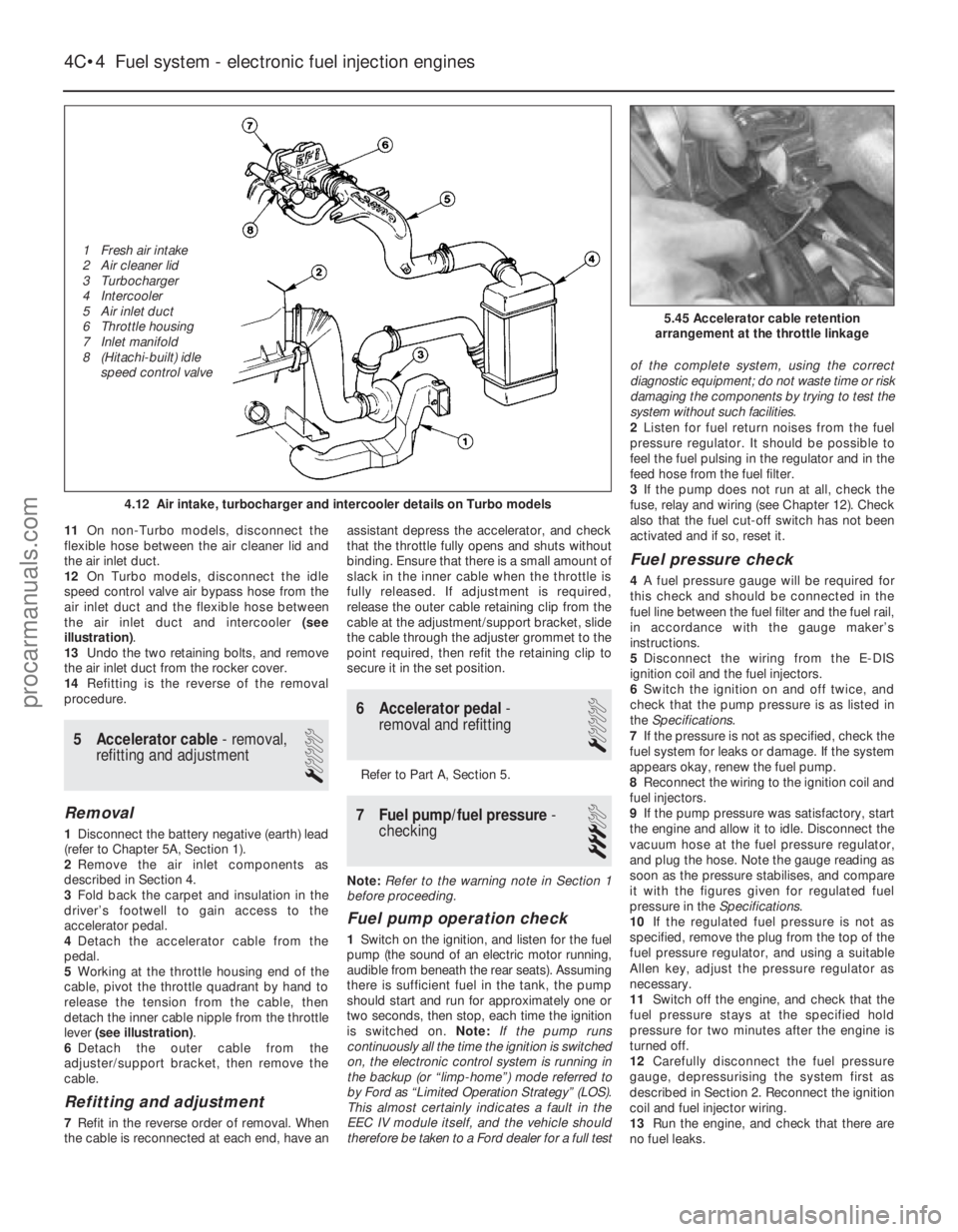
12 On Turbo models, disconnect the idle
speed control valve air bypass hose from the
air inlet duct and the flexible hose between
the air inlet duct and intercooler (see
illustration) .
13 Undo the two retaining bolts, and remove
the air inlet duct from the rocker cover.
14 Refitting is the reverse of the removal
procedure.
5 Accelerator cable - removal,
refitting and adjustment
1
Removal
1 Disconnect the battery negative (earth) lead
(refer to Chapter 5A, Section 1).
2 Remove the air inlet components as
described in Section 4.
3 Fold back the carpet and insulation in the
driver’s footwell to gain access to the
accelerator pedal.
4 Detach the accelerator cable from the
pedal.
5 Working at the throttle housing end of the
cable, pivot the throttle quadrant by hand to
release the tension from the cable, then
detach the inner cable nipple from the throttle
lever (see illustration) .
6 Detach the outer cable from the
adjuster/support bracket, then remove the
cable.
Refitting and adjustment
7 Refit in the reverse order of removal. When
the cable is reconnected at each end, have an assistant depress the accelerator, and check
that the throttle fully opens and shuts without
binding. Ensure that there is a small amount of
slack in the inner cable when the throttle is
fully released. If adjustment is required,
release the outer cable retaining clip from the
cable at the adjustment/support bracket, slide
the cable through the adjuster grommet to the
point required, then refit the retaining clip to
secure it in the set position.
6 Accelerator pedal
-
removal and refitting
1
Refer to Part A, Section 5.
7 Fuel pump/fuel pressure -
checking
3
Note: Refer to the warning note in Section 1
before proceeding.
Fuel pump operation check
1 Switch on the ignition, and listen for the fuel
pump (the sound of an electric motor running,
audible from beneath the rear seats). Assuming
there is sufficient fuel in the tank, the pump
should start and run for approximately one or
two seconds, then stop, each time the ignition
is switched on. Note:If the pump runs
continuously all the time the ignition is switched
on, the electronic control system is running in
the backup (or “limp-home”) mode referred to
by Ford as “Limited Operation Strategy” (LOS).
This almost certainly indicates a fault in the
EEC IV module itself, and the vehicle should
therefore be taken to a Ford dealer for a full test of the complete system, using the correct
diagnostic equipment; do not waste time or risk
damaging the components by trying to test the
system without such facilities.
2
Listen for fuel return noises from the fuel
pressure regulator. It should be possible to
feel the fuel pulsing in the regulator and in the
feed hose from the fuel filter.
3 If the pump does not run at all, check the
fuse, relay and wiring (see Chapter 12). Check
also that the fuel cut-off switch has not been
activated and if so, reset it.
Fuel pressure check
4 A fuel pressure gauge will be required for
this check and should be connected in the
fuel line between the fuel filter and the fuel rail,
in accordance with the gauge maker’s
instructions.
5 Disconnect the wiring from the E-DIS
ignition coil and the fuel injectors.
6 Switch the ignition on and off twice, and
check that the pump pressure is as listed in
the Specifications .
7 If the pressure is not as specified, check the
fuel system for leaks or damage. If the system
appears okay, renew the fuel pump.
8 Reconnect the wiring to the ignition coil and
fuel injectors.
9 If the pump pressure was satisfactory, start
the engine and allow it to idle. Disconnect the
vacuum hose at the fuel pressure regulator,
and plug the hose. Note the gauge reading as
soon as the pressure stabilises, and compare
it with the figures given for regulated fuel
pressure in the Specifications.
10 If the regulated fuel pressure is not as
specified, remove the plug from the top of the
fuel pressure regulator, and using a suitable
Allen key, adjust the pressure regulator as
necessary.
11 Switch off the engine, and check that the
fuel pressure stays at the specified hold
pressure for two minutes after the engine is
turned off.
12 Carefully disconnect the fuel pressure
gauge, depressurising the system first as
described in Section 2. Reconnect the ignition
coil and fuel injector wiring.
13 Run the engine, and check that there are
no fuel leaks.
4C•4 Fuel system - electronic fuel injection engines
5.45 Accelerator cable retention
arrangement at the throttle linkage
4.12 Air intake, turbocharger and intercooler details on Turbo models
1595Ford Fiesta Remake
1 Fresh air intake
2 Air cleaner lid
3 Turbocharger
4 Intercooler
5 Air inlet duct
6 Throttle housing
7 Inlet manifold
8 (Hitachi-built) idle
speed control valveprocarmanuals.com
http://vnx.su
Page 142 of 296
and flexible hose connecting the turbocharger
to the intercooler (see illustration 4.12) . Use
adhesive tape to seal the turbocharger ports
against the entry of dirt.
3 Unbolt the horn nearest the intercooler.
4 Unbolt the radiator/intercooler assembly
from the bonnet closure panel and the body
crossmember.
5 Move the assembly as far as possible
towards the engine, and unbolt the intercooler
from the radiator; withdraw the intercooler.
Refitting
6 Refitting is the reverse of the removal
procedure, tightening all nuts and bolts to the
specified torque settings, and not forgetting
to unseal the turbocharger openings before
reconnecting the intercooler pipe and hose.
18 Turbocharger boost control valve - removal and refitting
2
Removal
1Disconnect the battery negative (earth) lead
(refer to Chapter 5A, Section 1).
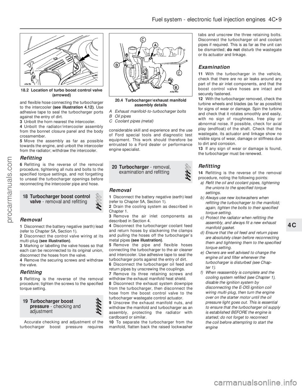
2 Disconnect the control valve wiring at its
multi-plug (see illustration) .
3 Marking or labelling the valve hoses so that
each can be reconnected to its original union,
disconnect the hoses from the valve.
4 Remove the securing screws and withdraw
the valve.
Refitting
5 Refitting is the reverse of the removal
procedure; tighten the screws to the specified
torque setting.
19 Turbocharger boost pressure - checking and
adjustment
5
Accurate checking and adjustment of the
turbocharger boost pressure requires considerable skill and experience and the use
of Ford special tools and diagnostic test
equipment. This work should therefore be
entrusted to a Ford dealer or performance
engine specialist.
20 Turbocharger
- removal,
examination and refitting
3
Removal
1 Disconnect the battery negative (earth) lead
(refer to Chapter 5A, Section 1).
2 Drain the cooling system as described in
Chapter 1.
3 Remove the air inlet components as
described in Section 4.
4 Disconnect the turbocharger coolant feed
and return hoses by slackening the clamps
and pulling the hoses off the turbocharger’s
metal pipes (see illustration) .
5 Remove the pipe and flexible hoses
connecting the turbocharger to the air cleaner
and intercooler. Use adhesive tape to seal the
turbocharger ports against the entry of dirt.
6 Disconnect the turbocharger oil feed and
return pipes by unscrewing the couplings.
7 Remove its three retaining screws and
withdraw the exhaust manifold heat shield.
8 Disconnect the exhaust system downpipe
from the turbocharger, then disconnect the
hose from the boost control valve to the
turbocharger wastegate control actuator.
9 Unscrew the exhaust manifold nuts, and
withdraw the manifold and turbocharger as an
assembly, protecting the radiator with
cardboard or similar.
10 To separate the turbocharger from the
manifold, flatten back the raised lockwasher tabs and unscrew the three retaining bolts.
Disconnect the turbocharger oil and coolant
pipes if required. This is as far as the unit can
be dismantled;
do notdisturb the wastegate
or its actuator and linkage.
Examination
11 With the turbocharger in the vehicle,
check that there are no air leaks around any
part of the air inlet components, and that the
boost control valve hoses are intact and
securely fastened.
12 With the turbocharger removed, check the
turbine wheels and blades (as far as possible)
for signs of wear or damage. Spin the turbine
and check that it rotates smoothly and easily,
with no sign of roughness, free play or
abnormal noise. If possible, check for axial
play (endfloat) of the shaft. Check that the
wastegate, its actuator and linkage show no
visible signs of wear, damage or stiffness due
to dirt and corrosion.
13 If any sign of wear or damage is found,
the turbocharger must be renewed.
Refitting
14 Refitting is the reverse of the removal
procedure, noting the following points: a) Refit the oil and coolant pipes, tightening
the unions to the specified torque
settings.
b) Always use new lockwashers when
refitting the turbocharger to the manifold;
again, tighten the bolts to their specified
torque setting.
c) Protect the radiator when refitting the
assembly, and always fit a new exhaust
manifold gasket.
d) Ensure that the oil feed and return pipes
are absolutely clean before reconnecting
them and tightening them to the specified
torque setting.
e) Owners are well advised to change the engine oil and filter whenever the
turbocharger is disturbed (see Chap-
ter 1).
f) When reassembly is complete and the
cooling system refilled (see Chapter 1),
disable the ignition system by
disconnecting the E-DIS ignition coil
wiring multi-plug, then turn the engine
over on the starter motor until the oil
pressure light goes out. This is essential
to ensure that the turbocharger oil supply
is established BEFORE the engine is
started; do not forget to reconnect
the coil before attempting to start the
engine
Fuel system - electronic fuel injection engines 4C•9
20.4 Turbocharger/exhaust manifold assembly details
A Exhaust manifold-to-turbocharger bolts
B Oil pipes
C Coolant pipes (metal)
4C
1595Ford Fiesta Remake
18.2 Location of turbo boost control valve (arrowed)
procarmanuals.com
http://vnx.su
Page 152 of 296
4E
1595Ford Fiesta Remake
Torque wrench settingsNmlbf ft
Pulse-air system piping sleeve nuts . . . . . . . . . . . . . . . . . . . . . . . . . . . . 32 24
Exhaust manifold to cylinder head: HCS engines . . . . . . . . . . . . . . . . . . . . . . . . . . . . . . . . . . . .\
. . . . . . . . 23 17
CVH engines (non turbocharged) . . . . . . . . . . . . . . . . . . . . . . . . . . . . 16 12
CVH engines (turbocharged) . . . . . . . . . . . . . . . . . . . . . . . . . . . . . . . . 28 to 31 21 to 23
PTE engines . . . . . . . . . . . . . . . . . . . . . . . . . . . . . . . . . . . .\
. . . . . . . . 16 12
Zetec engines . . . . . . . . . . . . . . . . . . . . . . . . . . . . . . . . . . . .\
. . . . . . . 16 12
Chapter 4 Part E:
Exhaust and emission control systems
Catalytic converter - general information and precautions . . . . . . . . 4
Emission control system check . . . . . . . . . . . . . . . . . . . .See Chapter 1
Evaporative emissions control system - checking and component
renewal . . . . . . . . . . . . . . . . . . . . . . . . . . . . . . . . . . . .\
. . . . . . . . . 6
Exhaust manifold - removal and refitting . . . . . . . . . . . . . . . . . . . . . 3
Exhaust system - renewal . . . . . . . . . . . . . . . . . . . . . . . . . . . . . . . . . 2 Exhaust system check . . . . . . . . . . . . . . . . . . . . . . . . . . .See Chapter 1
General information . . . . . . . . . . . . . . . . . . . . . . . . . . . . . . . . . . . .\
. . 1
Positive crankcase ventilation system - checking and component
renewal . . . . . . . . . . . . . . . . . . . . . . . . . . . . . . . . . . . .\
. . . . . . . . . 5
Pulse-air system - checking and component renewal . . . . . . . . . . . 7
Underbonnet check for fluid leaks and hose condition . .See Chapter 1
4E•1
Specifications Contents
Easy, suitable for
novice with little
experience Fairly easy,
suitable
for beginner with
some experience Fairly difficult,
suitable for competent
DIY mechanic
Difficult,
suitable for
experienced DIY
mechanic Very difficult,
suitable for expert DIY
or professional
Degrees of difficulty
54321
1 General information
Exhaust system
The exhaust system is composed of an
exhaust manifold, the front downpipe and
catalytic converter (where fitted), and a main
section incorporating two silencers. The
service replacement exhaust system consists
of three sections: the front downpipe/catalytic
converter, the intermediate pipe and front
silencer, and the tailpipe and rear silencer.
The system is suspended throughout its entire
length by rubber mountings.
Emission control systems
To minimise pollution of the atmosphere
from incompletely-burned and evaporating
gases, and to maintain good driveability and fuel economy, a number of emissions control
systems are used on these vehicles. They
include the following:
a) The engine management system
(comprising both fuel and ignition sub-
systems) itself.
b) Positive Crankcase Ventilation (PCV) system.
c) Evaporative emissions control (EVAP) system.
d) Pulse-air (PAIR) system.
e) Catalytic converter. The operation of the systems is described
in the following paragraphs.
Positive crankcase ventilation system
The function of the crankcase ventilation
system is to reduce the emissions of
unburned hydrocarbons from the crankcase,
and to minimise the formation of oil sludge. By
ensuring that a depression is created in the
crankcase under most operating conditions,
particularly at idle, and by positively inducing fresh air into the system, the oil vapours and
“blow-by” gases collected in the crankcase
are drawn from the crankcase, through the air
cleaner or oil separator, into the inlet tract, to
be burned by the engine during normal
combustion.
On HCS engines, the system consists of a
vented oil filler cap (with an integral mesh
filter) and a hose connecting it to a connector
on the underside of the air cleaner housing. A
further hose leads from the adapter/filter to
the inlet manifold. Under conditions of idle
and part-load, the emissions gases are
directed into the inlet manifold, and dispensed
with in the combustion process. Additional air
is supplied through two small orifices next to
the mushroom valve in the air cleaner
housing, the object of which is to prevent high
vacuum build-up. Under full-load conditions,
when the inlet manifold vacuum is weak, the
mushroom valve opens, and the emissions
are directed through the air cleaner housing
procarmanuals.com
http://vnx.su
Page 156 of 296
d)Refit the remaining parts in the reverse
order of removal. Tighten all fasteners to
the specified torque wrench settings
where given.
e) Where drained, refill the cooling system (see Chapter 1).
f) Run the engine, and check for exhaust
leaks. Check the coolant level when fully
warmed-up to normal operating
temperature.
4 Catalytic converter - general
information and precautions
The catalytic converter is a reliable and
simple device, which needs no maintenance
in itself, but there are some facts of which an
owner should be aware if the converter is to
function properly for its full service life. a) DO NOT use leaded petrol in a vehicle equipped with a catalytic converter - the
lead will coat the precious metals,
reducing their converting efficiency, and
will eventually destroy the converter.
b) Always keep the ignition and fuel systems
well-maintained in accordance with the
manufacturer’s schedule (see Chapter 1).
c) If the engine develops a misfire, do not drive the vehicle at all (or at least as little
as possible) until the fault is cured.
d) DO NOT push - or tow-start the vehicle -
this will soak the catalytic converter in
unburned fuel, causing it to overheat
when the engine does start.
e) DO NOT switch off the ignition at high engine speeds, ie do not “blip” the
throttle immediately before switching off.
f) DO NOT use fuel or engine oil additives - these may contain substances harmful to
the catalytic converter.
g) DO NOT continue to use the vehicle if the
engine burns oil to the extent of leaving a
visible trail of blue smoke.
h) Remember that the catalytic converter
operates at very high temperatures. DO
NOT, therefore, park the vehicle in dry
undergrowth, over long grass or piles of
dead leaves, after a long run.
I) Remember that the catalytic converter is FRAGILE. Do not strike it with tools
during servicing work.
j) In some cases, a sulphurous smell (like
that of rotten eggs) may be noticed from
the exhaust. This is common to many
catalytic converter-equipped vehicles.
Once the vehicle has covered a few
thousand miles, the problem should
disappear. Low quality fuel with a high
sulphur content will exacerbate this effect.
k) The catalytic converter used on a well-
maintained and well-driven vehicle should
last for between 50 000 and
100 000 miles. If the converter is no
longer effective, it must be renewed.
5 Positive crankcase ventilation system - checking
and component renewal
2
Checking
1 Checking procedures for the system
components are included in Chapter 1.
Component renewal - all
engines except Zetec
Air cleaner components
2 See Chapter 1.
Filter/oil separator and hoses
3All the components relating to the positive
crankcase ventilation system, with the
exception of the HCS engine filter/adapter
located on the underside of the air cleaner,
may be removed by simple disconnection and
withdrawal (having noted all connections for
subsequent refitting).
4 The refitting of all components is a reversal
of the removal procedure, ensuring that the
connections are correctly made.
Component renewal - Zetec
engines
Air cleaner components
5 See Chapter 1.
Positive Crankcase Ventilation (PCV)
valve
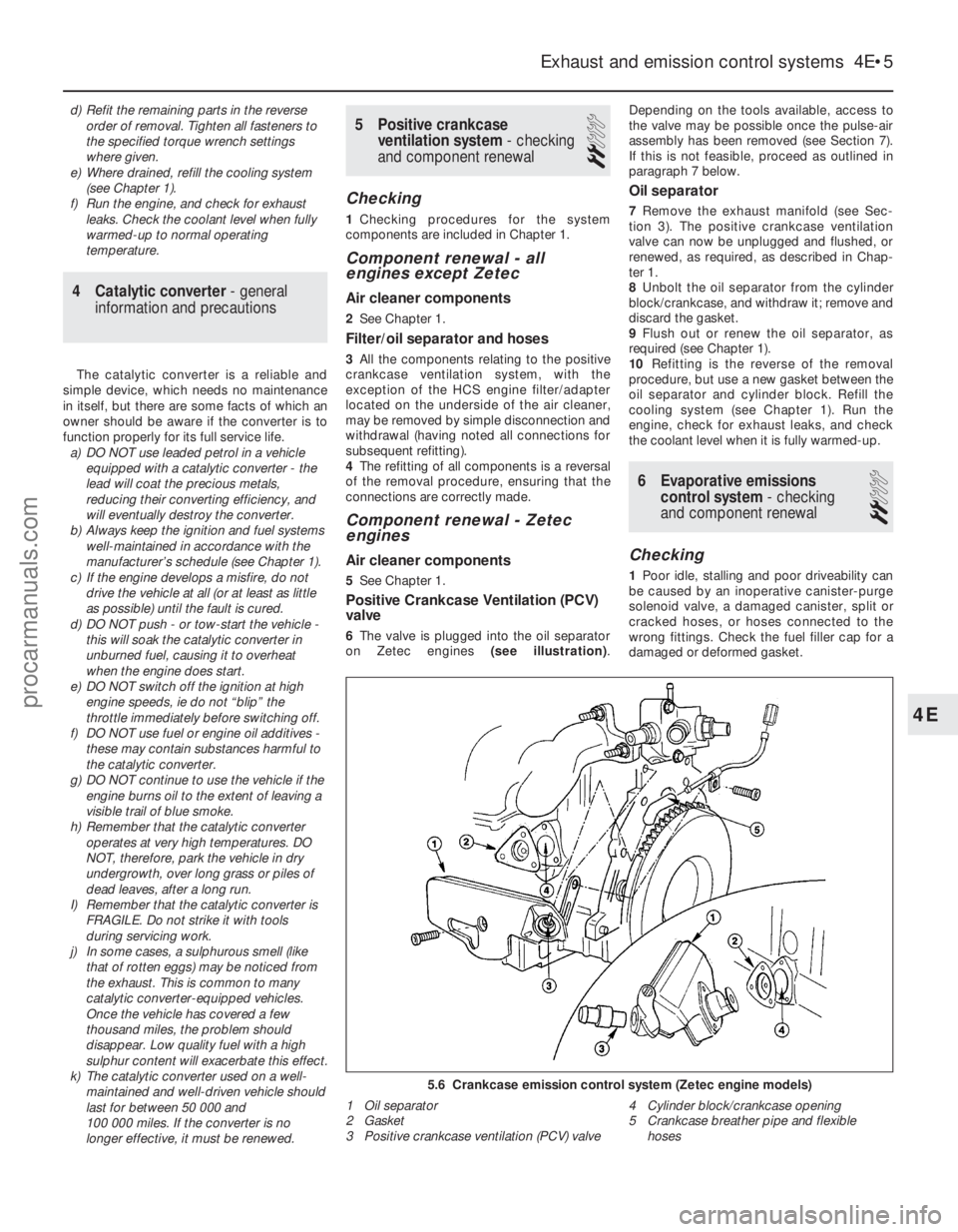
6The valve is plugged into the oil separator
on Zetec engines (see illustration).Depending on the tools available, access to
the valve may be possible once the pulse-air
assembly has been removed (see Section 7).
If this is not feasible, proceed as outlined in
paragraph 7 below.
Oil separator
7
Remove the exhaust manifold (see Sec-
tion 3). The positive crankcase ventilation
valve can now be unplugged and flushed, or
renewed, as required, as described in Chap-
ter 1.
8 Unbolt the oil separator from the cylinder
block/crankcase, and withdraw it; remove and
discard the gasket.
9 Flush out or renew the oil separator, as
required (see Chapter 1).
10 Refitting is the reverse of the removal
procedure, but use a new gasket between the
oil separator and cylinder block. Refill the
cooling system (see Chapter 1). Run the
engine, check for exhaust leaks, and check
the coolant level when it is fully warmed-up.
6 Evaporative emissions control system - checking
and component renewal
2
Checking
1 Poor idle, stalling and poor driveability can
be caused by an inoperative canister-purge
solenoid valve, a damaged canister, split or
cracked hoses, or hoses connected to the
wrong fittings. Check the fuel filler cap for a
damaged or deformed gasket.
Exhaust and emission control systems 4E•5
5.6 Crankcase emission control system (Zetec engine models)
1 Oil separator
2 Gasket
3 Positive crankcase ventilation (PCV) valve 4 Cylinder block/crankcase opening
5 Crankcase breather pipe and flexible
hoses
4E
1595Ford Fiesta Remakeprocarmanuals.com
http://vnx.su
Page 168 of 296
5B
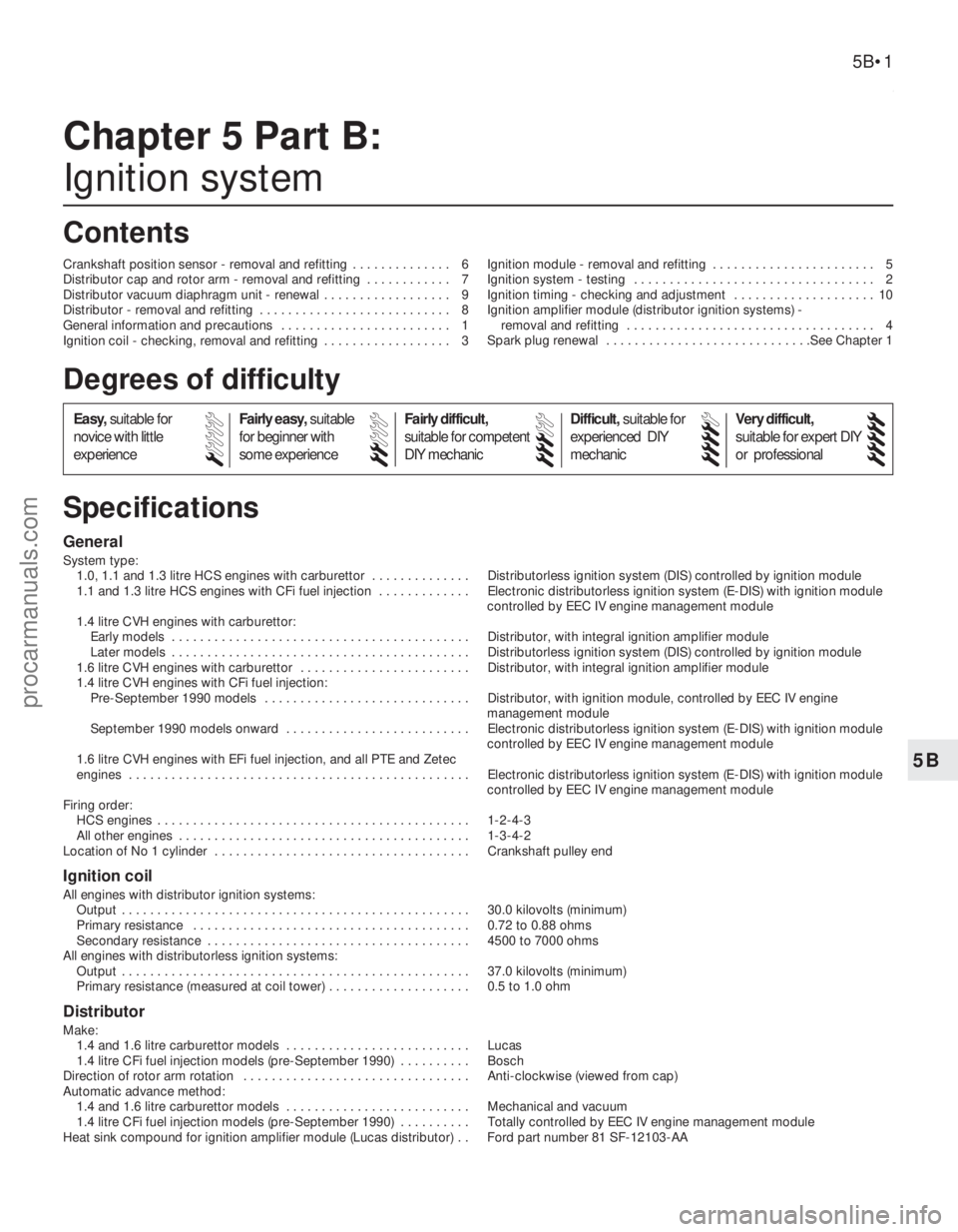
1595Ford Fiesta Remake
General
System type:1.0, 1.1 and 1.3 litre HCS engines with carburettor . . . . . . . . . . . . . . Distributorless ignition system (DIS) controlled by ignition module
1.1 and 1.3 litre HCS engines with CFi fuel injection . . . . . . . . . . . . . Electronic distributorless ignition system (E-DIS) with ignition module controlled by EEC IV engine management module
1.4 litre CVH engines with carburettor: Early models . . . . . . . . . . . . . . . . . . . . . . . . . . . . . . . . . . . .\
. . . . . . Distributor, with integral ignition amplifier module
Later models . . . . . . . . . . . . . . . . . . . . . . . . . . . . . . . . . . . .\
. . . . . . Distributorless ignition system (DIS) controlled by ignition module
1.6 litre CVH engines with carburettor . . . . . . . . . . . . . . . . . . . . . . . . Distributor, with integral ignition amplifier module
1.4 litre CVH engines with CFi fuel injection: Pre-September 1990 models . . . . . . . . . . . . . . . . . . . . . . . . . . . . . Distributor, with ignition module, controlled by EEC IV engine
management module
September 1990 models onward . . . . . . . . . . . . . . . . . . . . . . . . . . Electronic distributorless ignition system (E-DIS) with ignition module controlled by EEC IV engine management module
1.6 litre CVH engines with EFi fuel injection, and all PTE and Zetec
engines . . . . . . . . . . . . . . . . . . . . . . . . . . . . . . . . . . . .\
. . . . . . . . . . . . Electronic distributorless ignition system (E-DIS) with ignition module controlled by EEC IV engine management module
Firing order: HCS engines . . . . . . . . . . . . . . . . . . . . . . . . . . . . . . . . . . . .\
. . . . . . . . 1-2-4-3
All other engines . . . . . . . . . . . . . . . . . . . . . . . . . . . . . . . . . . . .\
. . . . . 1-3-4-2
Location of No 1 cylinder . . . . . . . . . . . . . . . . . . . . . . . . . . . . . . . . . . . .\
Crankshaft pulley end
Ignition coil
All engines with distributor ignition systems:
Output . . . . . . . . . . . . . . . . . . . . . . . . . . . . . . . . . . . .\
. . . . . . . . . . . . . 30.0 kilovolts (minimum)
Primary resistance . . . . . . . . . . . . . . . . . . . . . . . . . . . . . . . . . . . .\
. . . 0.72 to 0.88 ohms
Secondary resistance . . . . . . . . . . . . . . . . . . . . . . . . . . . . . . . . . . . .\
. 4500 to 7000 ohms
All engines with distributorless ignition systems: Output . . . . . . . . . . . . . . . . . . . . . . . . . . . . . . . . . . . .\
. . . . . . . . . . . . . 37.0 kilovolts (minimum)
Primary resistance (measured at coil tower) . . . . . . . . . . . . . . . . . . . . 0.5 to 1.0 ohm
Distributor
Make:
1.4 and 1.6 litre carburettor models . . . . . . . . . . . . . . . . . . . . . . . . . . Lucas
1.4 litre CFi fuel injection models (pre-September 1990) . . . . . . . . . . Bosch
Direction of rotor arm rotation . . . . . . . . . . . . . . . . . . . . . . . . . . . . . . . . Anti-clockwise (viewed from cap)
Automatic advance method: 1.4 and 1.6 litre carburettor models . . . . . . . . . . . . . . . . . . . . . . . . . . Mechanical and vacuum
1.4 litre CFi fuel injection models (pre-September 1990) . . . . . . . . . . Totally controlled by EEC IV engine management module
Heat sink compound for ignition amplifier module (Lucas distributor) . . Ford part number 81 SF-12103-AA
Chapter 5 Part B:
Ignition system
Crankshaft position sensor - removal and refitting . . . . . . . . . . . . . . 6
Distributor cap and rotor arm - removal and refitting . . . . . . . . . . . . 7
Distributor vacuum diaphragm unit - renewal . . . . . . . . . . . . . . . . . . 9
Distributor - removal and refitting . . . . . . . . . . . . . . . . . . . . . . . . . . . 8
General information and precautions . . . . . . . . . . . . . . . . . . . . . . . . 1
Ignition coil - checking, removal and refitting . . . . . . . . . . . . . . . . . . 3 Ignition module - removal and refitting . . . . . . . . . . . . . . . . . . . . . . . 5
Ignition system - testing . . . . . . . . . . . . . . . . . . . . . . . . . . . . . . . . . . 2
Ignition timing - checking and adjustment . . . . . . . . . . . . . . . . . . . . 10
Ignition amplifier module (distributor ignition systems) -
removal and refitting . . . . . . . . . . . . . . . . . . . . . . . . . . . . . . . . . . . 4
Spark plug renewal . . . . . . . . . . . . . . . . . . . . . . . . . . . . .See Chapter 1
5B•1
Specifications Contents
Easy, suitable for
novice with little
experience Fairly easy,
suitable
for beginner with
some experience Fairly difficult,
suitable for competent
DIY mechanic
Difficult,
suitable for
experienced DIY
mechanic Very difficult,
suitable for expert DIY
or professional
Degrees of difficulty
54321
procarmanuals.com
http://vnx.su
Page 171 of 296
3 Ignition coil- checking,
removal and refitting
2
Distributor ignition systems
Checking
1 Accurate checking of the coil output
requires the use of special test equipment and
should be left to a dealer or suitably equipped
automotive electrician. It is however possible
to check the primary and secondary winding
resistance using an ohmmeter as follows.
2 Disconnect the battery negative (earth) lead
(refer to Part A, Section 1).
3 Remove the vehicle jack from its storage
position by unscrewing its retainer. The
ignition coil is mounted below.
4 To check the primary resistance (with all
leads disconnected if the coil is fitted),
connect the ohmmeter across the coil positive
and negative terminals. The resistance should
be as given in the Specificationsat the
beginning of this Chapter.
5 To check the secondary resistance (with all
leads disconnected if the coil is fitted),
connect one lead from the ohmmeter to the
coil negative terminal, and the other lead to
the centre HT terminal. Again the resistance
should be as given in the Specifications.
6 If any of the measured values vary
significantly from the figures given in the
Specifications , the coil should be renewed.
7 If a new coil is to be fitted, ensure that it is
of the correct type. The appropriate Ford
supplied ignition coil is identified by a red
label, and will be one of three different makes,
all of which are fully interchangeable. Bosch
and Femsa coils are fitted with protective
plastic covers, and Polmot coils are fitted with
an internal fusible link. Note that contact
breaker ignition coils are not interchangeable
with the required breakerless type and could
cause ignition module failure if used.
Removal
8 If not already done, remove the vehicle jack from its storage position by unscrewing its
retainer. The ignition coil is mounted below.
9
Disconnect the battery negative (earth) lead
(refer to Part A, Section 1).
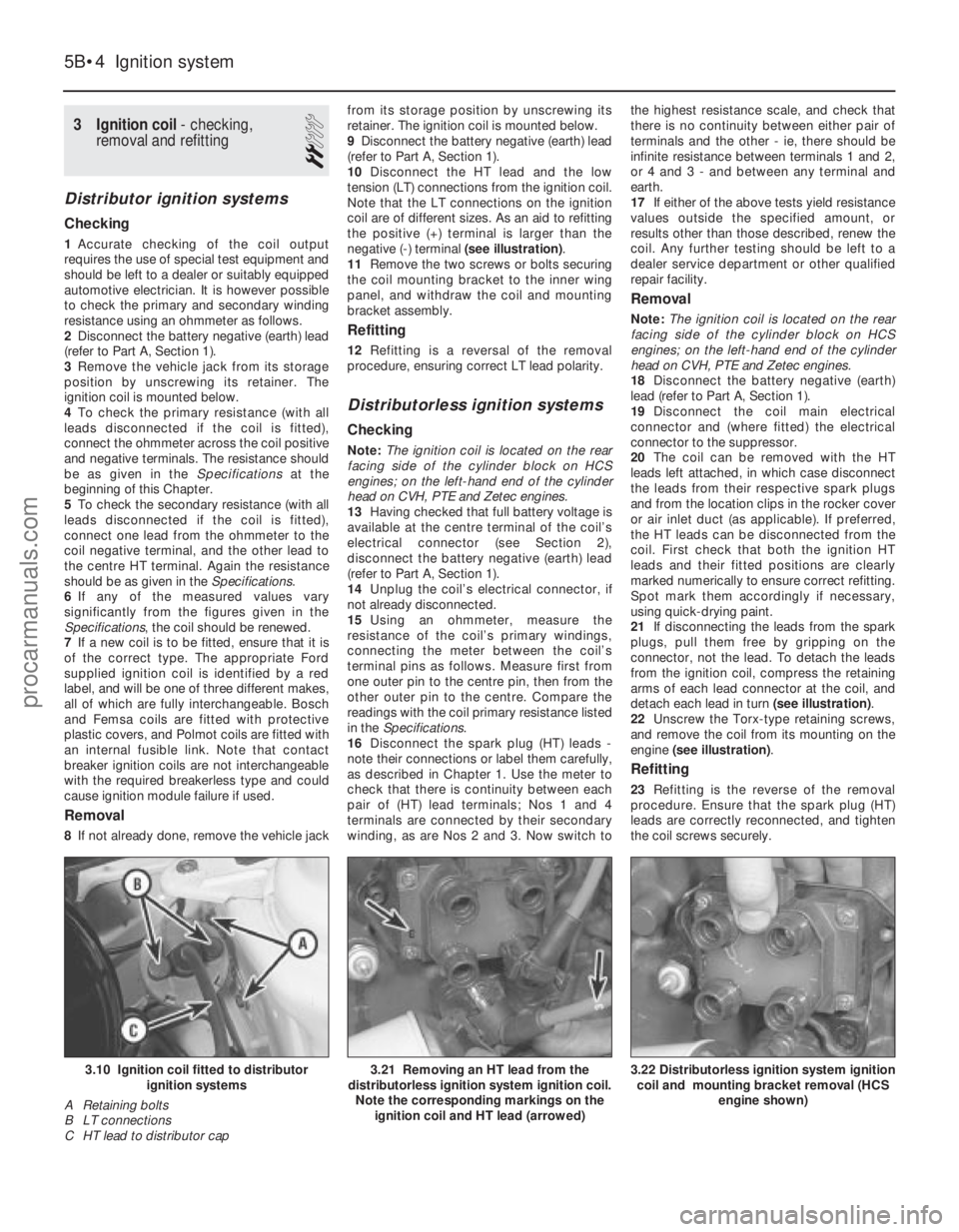
10 Disconnect the HT lead and the low
tension (LT) connections from the ignition coil.
Note that the LT connections on the ignition
coil are of different sizes. As an aid to refitting
the positive (+) terminal is larger than the
negative (-) terminal (see illustration).
11 Remove the two screws or bolts securing
the coil mounting bracket to the inner wing
panel, and withdraw the coil and mounting
bracket assembly.
Refitting
12 Refitting is a reversal of the removal
procedure, ensuring correct LT lead polarity.
Distributorless ignition systems
Checking
Note: The ignition coil is located on the rear
facing side of the cylinder block on HCS
engines; on the left-hand end of the cylinder
head on CVH, PTE and Zetec engines.
13 Having checked that full battery voltage is
available at the centre terminal of the coil’s
electrical connector (see Section 2),
disconnect the battery negative (earth) lead
(refer to Part A, Section 1).
14 Unplug the coil’s electrical connector, if
not already disconnected.
15 Using an ohmmeter, measure the
resistance of the coil’s primary windings,
connecting the meter between the coil’s
terminal pins as follows. Measure first from
one outer pin to the centre pin, then from the
other outer pin to the centre. Compare the
readings with the coil primary resistance listed
in the Specifications .
16 Disconnect the spark plug (HT) leads -
note their connections or label them carefully,
as described in Chapter 1. Use the meter to
check that there is continuity between each
pair of (HT) lead terminals; Nos 1 and 4
terminals are connected by their secondary
winding, as are Nos 2 and 3. Now switch to the highest resistance scale, and check that
there is no continuity between either pair of
terminals and the other - ie, there should be
infinite resistance between terminals 1 and 2,
or 4 and 3 - and between any terminal and
earth.
17
If either of the above tests yield resistance
values outside the specified amount, or
results other than those described, renew the
coil. Any further testing should be left to a
dealer service department or other qualified
repair facility.
Removal
Note: The ignition coil is located on the rear
facing side of the cylinder block on HCS
engines; on the left-hand end of the cylinder
head on CVH, PTE and Zetec engines.
18 Disconnect the battery negative (earth)
lead (refer to Part A, Section 1).
19 Disconnect the coil main electrical
connector and (where fitted) the electrical
connector to the suppressor.
20 The coil can be removed with the HT
leads left attached, in which case disconnect
the leads from their respective spark plugs
and from the location clips in the rocker cover
or air inlet duct (as applicable). If preferred,
the HT leads can be disconnected from the
coil. First check that both the ignition HT
leads and their fitted positions are clearly
marked numerically to ensure correct refitting.
Spot mark them accordingly if necessary,
using quick-drying paint.
21 If disconnecting the leads from the spark
plugs, pull them free by gripping on the
connector, not the lead. To detach the leads
from the ignition coil, compress the retaining
arms of each lead connector at the coil, and
detach each lead in turn (see illustration).
22 Unscrew the Torx-type retaining screws,
and remove the coil from its mounting on the
engine (see illustration) .
Refitting
23Refitting is the reverse of the removal
procedure. Ensure that the spark plug (HT)
leads are correctly reconnected, and tighten
the coil screws securely.
5B•4 Ignition system
3.22 Distributorless ignition system ignition coil and mounting bracket removal (HCS engine shown)3.21 Removing an HT lead from the
distributorless ignition system ignition coil. Note the corresponding markings on the ignition coil and HT lead (arrowed)3.10 Ignition coil fitted to distributor
ignition systems
A Retaining bolts
B LT connections
C HT lead to distributor cap
1595Ford Fiesta Remakeprocarmanuals.com
http://vnx.su
Page 174 of 296
after the remaining components have been
refitted and the relevant connections made.
17Refit the rotor arm (if removed), distributor
cap, suppressor shield (as applicable) and HT
leads, making reference to Section 7, then
reconnect the wiring multi-plug.
18 Reconnect the battery negative lead.
19 If one or both of the punch marks are
missing after component renewal, the vehicle
will need to be taken to a Ford dealer for
accurate ignition timing checking and, if
necessary, adjustment. This can only be
carried out with the EEC IV engine
management module in “self-test” mode
and connected to the Ford specialised test
equipment (see Section 10, paragraph 19).
9 Distributor vacuum diaphragm unit - renewal
2
Note: Check parts availability before
proceeding with this operation.
1 Remove the distributor, as described in
Section 8.
2 With the distributor on the workbench,
remove the ignition amplifier module (see
Section 4) and the distributor cap and rotor
arm (if not already done).
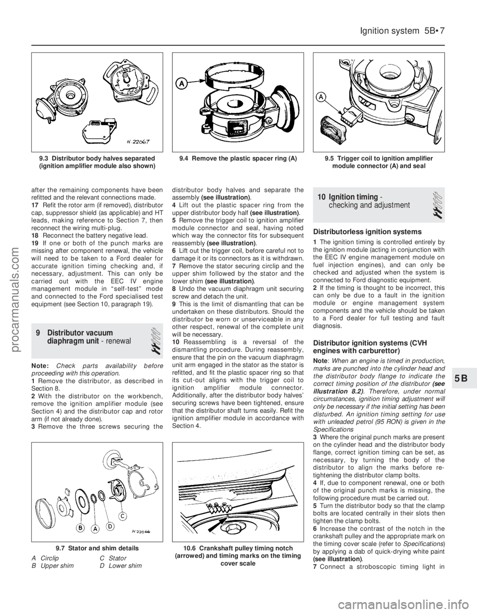
3 Remove the three screws securing the distributor body halves and separate the
assembly
(see illustration) .
4 Lift out the plastic spacer ring from the
upper distributor body half (see illustration).
5 Remove the trigger coil to ignition amplifier
module connector and seal, having noted
which way the connector fits for subsequent
reassembly (see illustration) .
6 Lift out the trigger coil, before careful not to
damage it or its connectors as it is withdrawn.
7 Remove the stator securing circlip and the
upper shim followed by the stator and the
lower shim (see illustration) .
8 Undo the vacuum diaphragm unit securing
screw and detach the unit.
9 This is the limit of dismantling that can be
undertaken on these distributors. Should the
distributor be worn or unserviceable in any
other respect, renewal of the complete unit
will be necessary.
10 Reassembling is a reversal of the
dismantling procedure. During reassembly,
ensure that the pin on the vacuum diaphragm
unit arm engaged in the stator as the stator is
refitted, and fit the plastic spacer ring so that
its cut-out aligns with the trigger coil to
ignition amplifier module connector.
Additionally, after the distributor body halves’
securing screws have been tightened, ensure
that the distributor shaft turns easily. Refit the
ignition amplifier module in accordance with
Section 4.
10 Ignition timing -
checking and adjustment
2
Distributorless ignition systems
1 The ignition timing is controlled entirely by
the ignition module (acting in conjunction with
the EEC IV engine management module on
fuel injection engines), and can only be
checked and adjusted when the system is
connected to Ford diagnostic equipment.
2 If the timing is thought to be incorrect, this
can only be due to a fault in the ignition
module or engine management system
components and the vehicle should be taken
to a Ford dealer for full testing and fault
diagnosis.
Distributor ignition systems (CVH
engines with carburettor)
Note: When an engine is timed in production,
marks are punched into the cylinder head and
the distributor body flange to indicate the
correct timing position of the distributor (see
illustration 8.2) . Therefore, under normal
circumstances, ignition timing adjustment will
only be necessary if the initial setting has been
disturbed. An ignition timing setting for use
with unleaded petrol (95 RON) is given in the
Specifications
3 Where the original punch marks are present
on the cylinder head and the distributor body
flange, correct ignition timing can be set, as
necessary, by turning the body of the
distributor to align the marks before re-
tightening the distributor clamp bolts.
4 If, due to component renewal, one or both
of the original punch marks is missing, the
following procedure must be carried out.
5 Turn the distributor body so that the clamp
bolts are located centrally in their slots then
tighten the clamp bolts.
6 Increase the contrast of the notch in the
crankshaft pulley and the appropriate mark on
the timing cover scale (refer to Specifications)
by applying a dab of quick-drying white paint
(see illustration) .
7 Connect a stroboscopic timing light in
Ignition system 5B•7
9.5 Trigger coil to ignition amplifier
module connector (A) and seal9.4 Remove the plastic spacer ring (A)9.3 Distributor body halves separated
(ignition amplifier module also shown)
10.6 Crankshaft pulley timing notch
(arrowed) and timing marks on the timing cover scale9.7 Stator and shim details
A Circlip C Stator
B Upper shim D Lower shim
5B
1595Ford Fiesta Remakeprocarmanuals.com
http://vnx.su
Page 179 of 296
15Unplug the hydraulic hose, and check that
the unions are clean. Reconnect the caliper to
the hose so that the hose is not twisted or
strained. The hose union connection can be
fully tightened when the caliper is refitted.
16 Refit the brake pads as described in
Section 2.
17 The brake hydraulic hose can now be fully
tightened. When secured, turn the steering
from lock-to-lock to ensure that the hose
does not foul on the wheel housing or
suspension components.
18 Bleed the brake hydraulic system as
described in Section 13 or 14 according to
type. Providing suitable precautions were
taken to minimise loss of fluid, it should only
be necessary to bleed the relevant front
brake.
19 Refit the roadwheel, lower the vehicle to
the ground, then tighten the wheel nuts to the
specified torque.
4 Front brake disc - inspection,
removal and refitting
2
Note: Before starting work, refer to the
warning at the beginning of Section 2
concerning the dangers of asbestos dust.
Inspection
Note: If a disc requires renewal, BOTH front
discs should be renewed or reground at the
same time to ensure even and consistent
braking. New brake pads should also be fitted.
1 Chock the rear wheels then jack up the
front of the car and support it on axle stands
(see “Jacking and Vehicle Support” ). Remove
the appropriate front roadwheel.
2 Temporarily refit two of the wheel nuts to
diagonally-opposite studs, with the flat sides
of the nuts against the disc. Tighten the nuts
progressively, to hold the disc firmly.
3 Scrape any corrosion from the disc. Rotate
the disc, and examine it for deep scoring,
grooving or cracks. Using a micrometer,
measure the thickness of the disc in several
places. Light wear and scoring is normal, but
if excessive, the disc should be removed, and
either reground by a specialist, or renewed. If regrinding is undertaken, at least the minimum
thickness must be maintained. Obviously, if
the disc is cracked, it must be renewed.
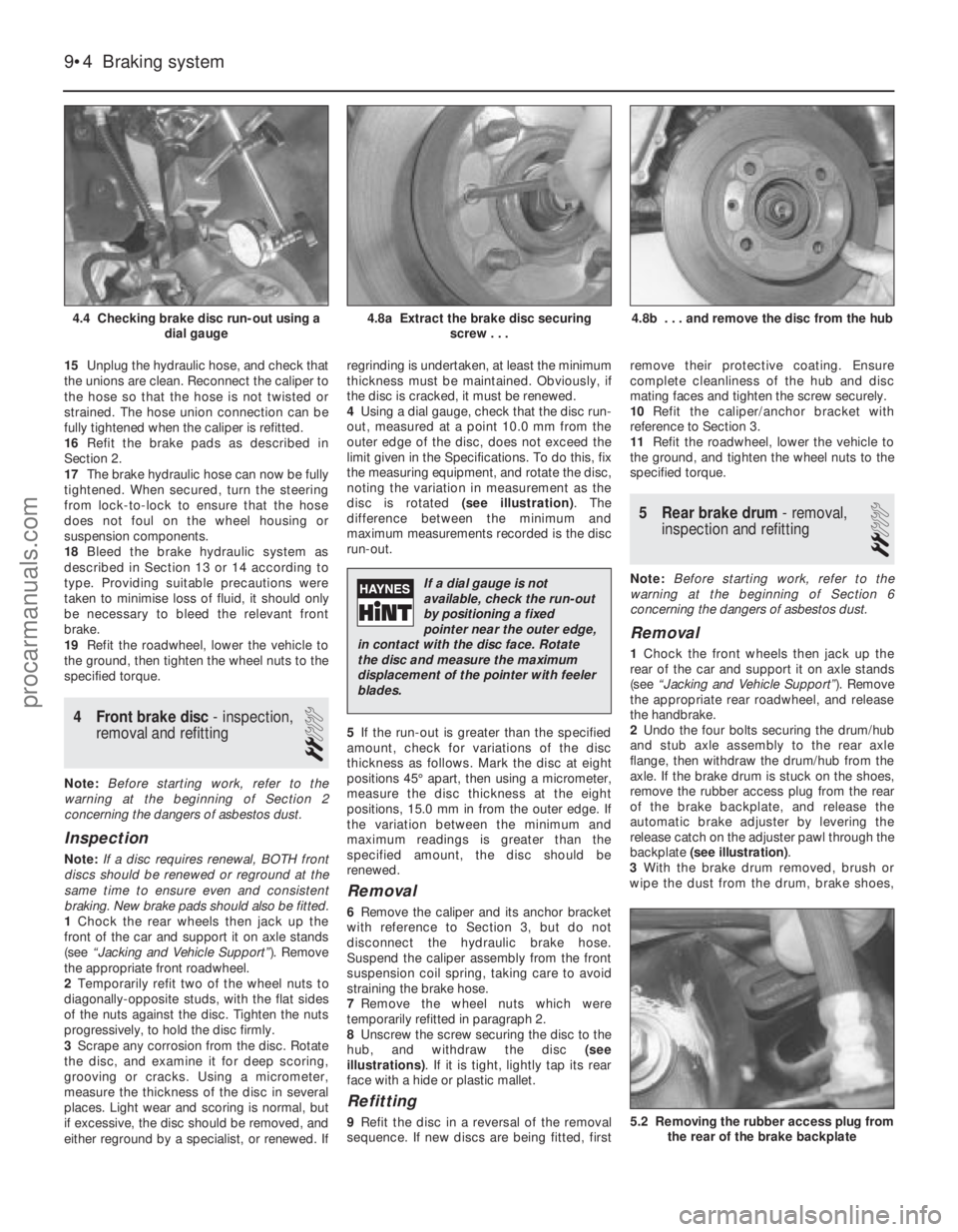
4
Using a dial gauge, check that the disc run-
out, measured at a point 10.0 mm from the
outer edge of the disc, does not exceed the
limit given in the Specifications. To do this, fix
the measuring equipment, and rotate the disc,
noting the variation in measurement as the
disc is rotated (see illustration). The
difference between the minimum and
maximum measurements recorded is the disc
run-out.
5 If the run-out is greater than the specified
amount, check for variations of the disc
thickness as follows. Mark the disc at eight
positions 45° apart, then using a micrometer,
measure the disc thickness at the eight
positions, 15.0 mm in from the outer edge. If
the variation between the minimum and
maximum readings is greater than the
specified amount, the disc should be
renewed.
Removal
6 Remove the caliper and its anchor bracket
with reference to Section 3, but do not
disconnect the hydraulic brake hose.
Suspend the caliper assembly from the front
suspension coil spring, taking care to avoid
straining the brake hose.
7 Remove the wheel nuts which were
temporarily refitted in paragraph 2.
8 Unscrew the screw securing the disc to the
hub, and withdraw the disc (see
illustrations) . If it is tight, lightly tap its rear
face with a hide or plastic mallet.
Refitting
9 Refit the disc in a reversal of the removal
sequence. If new discs are being fitted, first remove their protective coating. Ensure
complete cleanliness of the hub and disc
mating faces and tighten the screw securely.
10
Refit the caliper/anchor bracket with
reference to Section 3.
11 Refit the roadwheel, lower the vehicle to
the ground, and tighten the wheel nuts to the
specified torque.
5 Rear brake drum - removal,
inspection and refitting
2
Note: Before starting work, refer to the
warning at the beginning of Section 6
concerning the dangers of asbestos dust.
Removal
1 Chock the front wheels then jack up the
rear of the car and support it on axle stands
(see “Jacking and Vehicle Support” ). Remove
the appropriate rear roadwheel, and release
the handbrake.
2 Undo the four bolts securing the drum/hub
and stub axle assembly to the rear axle
flange, then withdraw the drum/hub from the
axle. If the brake drum is stuck on the shoes,
remove the rubber access plug from the rear
of the brake backplate, and release the
automatic brake adjuster by levering the
release catch on the adjuster pawl through the
backplate (see illustration) .
3 With the brake drum removed, brush or
wipe the dust from the drum, brake shoes,
9•4 Braking system
5.2 Removing the rubber access plug from
the rear of the brake backplate
4.8b . . . and remove the disc from the hub4.8a Extract the brake disc securing screw . . .4.4 Checking brake disc run-out using a dial gauge
1595Ford Fiesta Remake
If a dial gauge is not
available, check the run-out
by positioning a fixed
pointer near the outer edge,
in contact with the disc face. Rotate
the disc and measure the maximum
displacement of the pointer with feeler
blades.
procarmanuals.com
http://vnx.su