1989 FORD FIESTA park assist
[x] Cancel search: park assistPage 17 of 296
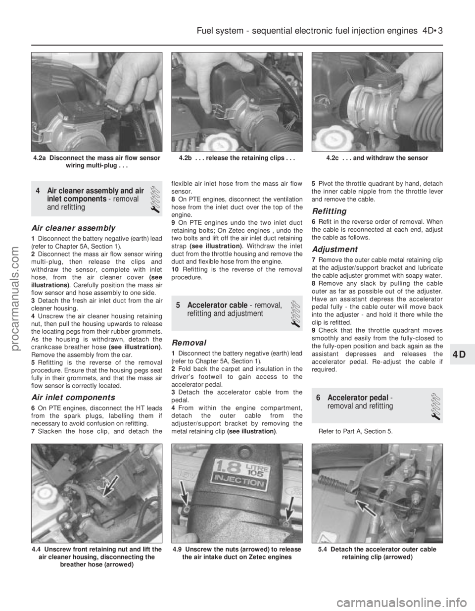
lubricant, together with dirt and water entry,
resulting in rapid deterioration of the balljoints
or steering gear.
3Check the power-assisted steering fluid
hoses (where fitted) for chafing or
deterioration, and the pipe and hose unions
for fluid leaks. Also check for signs of fluid
leakage under pressure from the steering gear
rubber gaiters, which would indicate failed
fluid seals within the steering gear.
4 Grasp the roadwheel at the 12 o’clock and
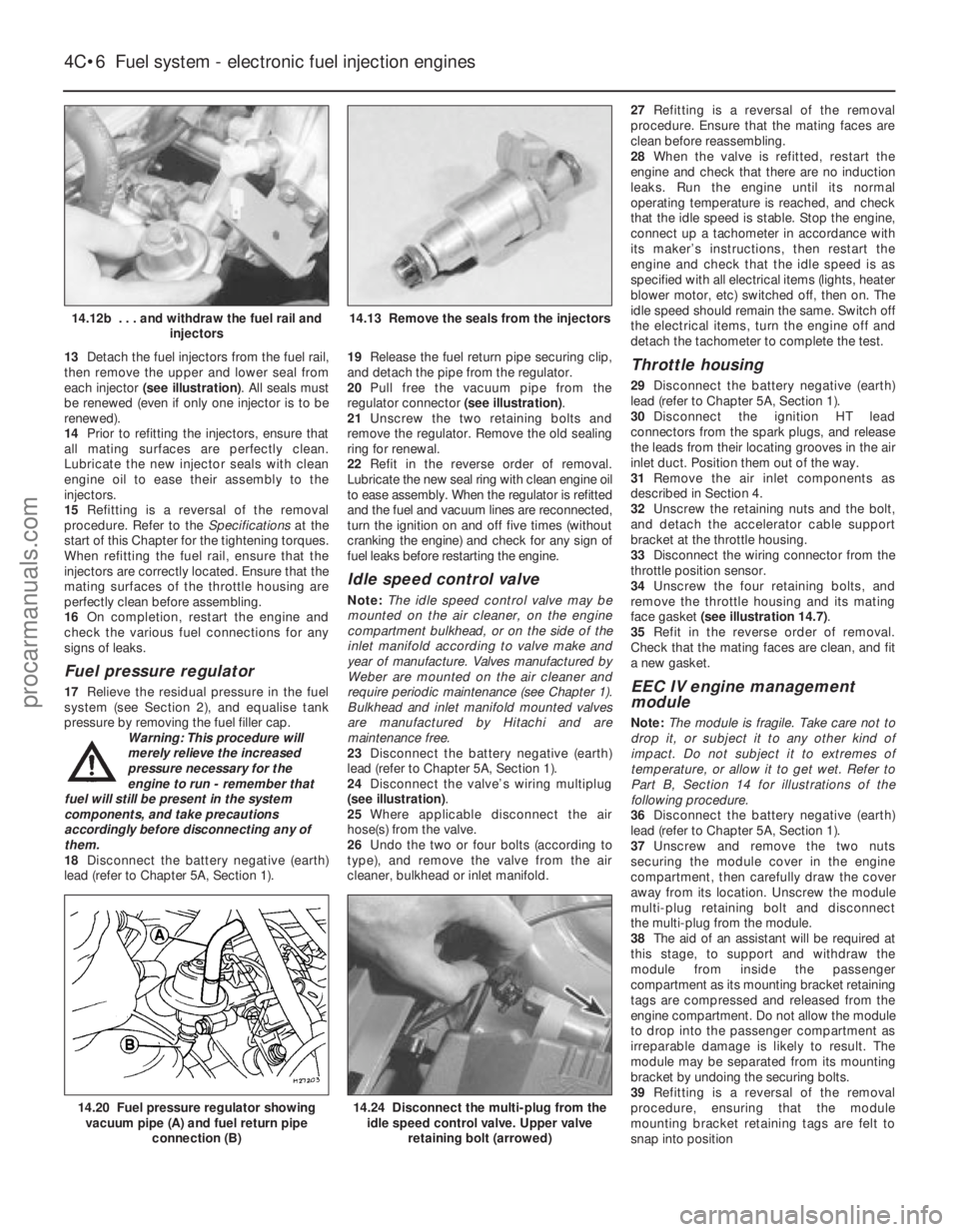
6 o’clock positions, and try to rock it. Very
slight free play may be felt, but if the
movement is appreciable, further investigation
is necessary to determine the source.
Continue rocking the wheel while an assistant
depresses the footbrake. If the movement is
now eliminated or significantly reduced, it is
likely that the hub bearings are at fault. If the
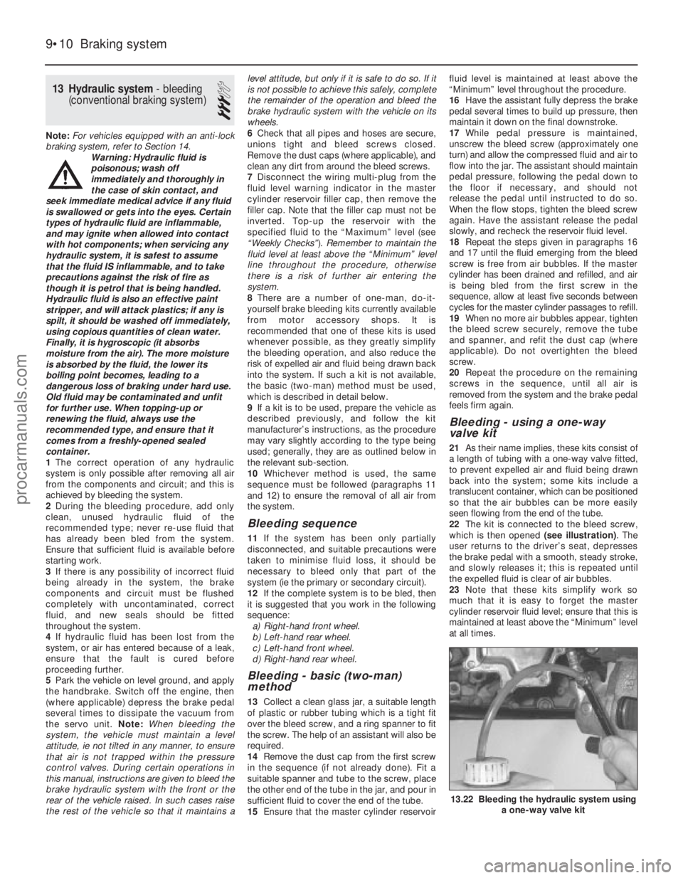
free play is still evident with the footbrake
depressed, then there is wear in the
suspension joints or mountings.
5 Now grasp the wheel at the 9 o’clock and 3
o’clock positions, and try to rock it as before.
Any movement felt now may again be caused
by wear in the hub bearings or the steering
track rod balljoints. If the outer track rod end
balljoint is worn, the visual movement will be
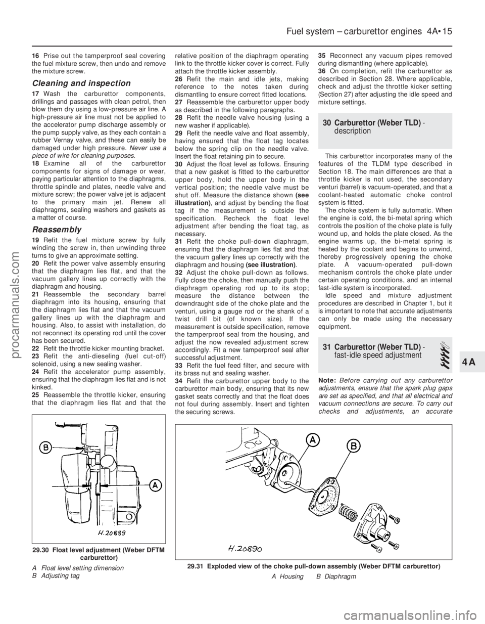
obvious. If the inner joint is suspect, it can be
felt by placing a hand over the rack-and-
pinion rubber gaiter, and gripping the track
rod. If the wheel is now rocked, movement will
be felt at the inner joint if wear has taken
place.
6 Using a large screwdriver or flat bar, check
for wear in the suspension mounting bushes
by levering between the relevant suspension
component and its attachment point. Some
movement is to be expected, as the
mountings are made of rubber, but excessive
wear should be obvious. Also check the
condition of any visible rubber bushes,
looking for splits, cracks or contamination of
the rubber.
7 With the vehicle standing on its wheels,
have an assistant turn the steering wheel
back-and-forth, about an eighth of a turn each
way. There should be very little, if any, lost
movement between the steering wheel and
roadwheels. If this is not the case, closely
observe the joints and mountings previously described, but in addition, check the steering
column universal joints for wear, and also
check the rack-and-pinion steering gear itself.
Rear suspension check
8
Chock the front wheels then jack up the
rear of the car and support it on axle stands
(see “Jacking and Vehicle Support” ). Remove
the rear roadwheels.
9 Check the rear hub bearings for wear, using
the method described for the front hub
bearings (paragraph 4).
10 Using a large screwdriver or flat bar,
check for wear in the suspension mounting
bushes by levering between the relevant
suspension component and its attachment
point. Some movement is to be expected, as
the mountings are made of rubber, but
excessive wear should be obvious. Check the
condition of the shock absorbers and their
bushes/mountings. On Van models, check the
leaves of the leaf springs for signs of cracking,
distortion, or other damage.
Roadwheel check and balancing
11 Periodically remove the roadwheels, and
clean any dirt or mud from the inside and
outside surfaces. Examine the wheel rims for
signs of rusting, corrosion or other damage.
Light alloy wheels are easily damaged by
“kerbing” whilst parking, and similarly, steel
wheels may become dented or buckled.
Renewal of the wheel is very often the only
course of remedial action possible.
12 The balance of each wheel and tyre
assembly should be maintained, not only to
avoid excessive tyre wear, but also to avoid
wear in the steering and suspension
components. Wheel imbalance is normally
signified by vibration through the vehicle’s
bodyshell, although in many cases it is
particularly noticeable through the steering
wheel. Conversely, it should be noted that
wear or damage in suspension or steering
components may cause excessive tyre wear.
Out-of-round or out-of-true tyres, damaged
wheels and wheel bearing wear/
maladjustment also fall into this category.
Balancing will not usually cure vibration
caused by such wear.
13 Wheel balancing may be carried out with
the wheel either on or off the vehicle. If balanced on the vehicle, ensure that the
wheel-to-hub relationship is marked in some
way prior to subsequent wheel removal, so
that it may be refitted in its original position.
11 Driveshaft rubber gaiter and
CV joint check
1
1The driveshaft rubber gaiters are very
important, because they prevent dirt, water
and foreign material from entering and
damaging the constant velocity (CV) joints.
External contamination can cause the gaiter
material to deteriorate prematurely, so it’s a
good idea to wash the gaiters with soap and
water occasionally.
2 With the vehicle raised and securely
supported on axle stands, turn the steering
onto full-lock, then slowly rotate each front
wheel in turn. Inspect the condition of the
outer constant velocity (CV) joint rubber
gaiters, squeezing the gaiters to open out the
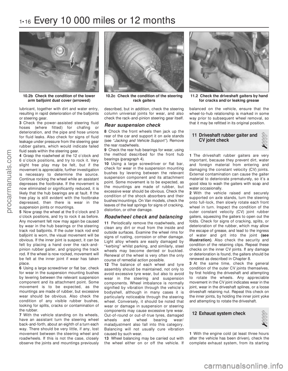
folds. Check for signs of cracking, splits, or
deterioration of the rubber, which may allow
the escape of grease, and lead to the ingress
of water and grit into the joint (see
illustration) . Also check the security and
condition of the retaining clips. Repeat these
checks on the inner CV joints. If any damage
or deterioration is found, the gaiters should be
renewed as described in Chapter 8.
3 At the same time, check the general
condition of the outer CV joints themselves,
by first holding the driveshaft and attempting
to rotate the wheels. Any appreciable
movement in the CV joint indicates wear in the
joint, wear in the driveshaft splines, or a loose
driveshaft retaining nut. Repeat this check on
the inner joints, by holding the inner joint yoke
and attempting to rotate the driveshaft.
12 Exhaust system check
1
1 With the engine cold (at least three hours
after the vehicle has been driven), check the
complete exhaust system, from its starting
1•16Every 10 000 miles or 12 months
11.2 Check the driveshaft gaiters by hand for cracks and/or leaking grease10.2c Check the condition of the steering rack gaiters10.2b Check the condition of the lowerarm balljoint dust cover (arrowed)
1595Ford Fiesta Remakeprocarmanuals.com
http://vnx.su
Page 30 of 296
connecting rods (after removing the cylinder
head and sump) without removing the engine.
However, this is not recommended. Work of
this nature is more easily and thoroughly
completed with the engine on the bench, as
described in Chapter 2D.
2 Compression test-
description and interpretation
2
1 When engine performance is down, or if
misfiring occurs which cannot be attributed to
the ignition or fuel systems, a compression
test can provide diagnostic clues as to the
engine’s condition. If the test is performed
regularly, it can give warning of trouble before
any other symptoms become apparent.
2 The engine must be fully warmed-up to
normal operating temperature, the oil level
must be correct and the battery must be fully
charged. The aid of an assistant will also be
required.
3 On fuel injection engines, refer to Chap-
ter 12 and remove the fuel pump fuse from the
fusebox. Now start the engine and allow it to
run until it stalls.
4 Disable the ignition system by
disconnecting the multi-plug from the DIS or
E-DIS ignition coil. Remove all the spark plugs
with reference to Chapter 1 if necessary.
5 Fit a compression tester to the No 1
cylinder spark plug hole - the type of tester
which screws into the plug thread is to be
preferred.
6 Arrange for an assistant to hold the
accelerator pedal fully depressed to the floor,
while at the same time cranking the engine
over for several seconds on the starter motor.
Observe the compression gauge reading. The
compression will build up fairly quickly in a
healthy engine. Low compression on the first
stroke, followed by gradually-increasing
pressure on successive strokes, indicates
worn piston rings. A low compression on the
first stroke which does not rise on successive
strokes, indicates leaking valves or a blown
head gasket (a cracked cylinder head could
also be the cause). Deposits on the underside
of the valve heads can also cause low
compression. Record the highest gauge
reading obtained, then repeat the procedure
for the remaining cylinders.
7 Due to the variety of testers available, and
the fluctuation in starter motor speed when
cranking the engine, different readings
are often obtained when carrying out
the compression test. For this reason, actual
compression pressure figures are not quoted
by Ford. However, the most important factor
is that the compression pressures are uniform
in all cylinders, and that is what this test is
mainly concerned with.
8 Add some engine oil (about three squirts
from a plunger type oil can) to each cylinder
through the spark plug holes, and then repeat
the test. 9
If the compression increases after the oil is
added, it is indicative that the piston rings are
definitely worn. If the compression does not
increase significantly, the leakage is occurring
at the valves or the head gasket. Leakage
past the valves may be caused by burned
valve seats and/or faces, or warped, cracked
or bent valves.
10 If two adjacent cylinders have equally low
compressions, it is most likely that the head
gasket has blown between them. The
appearance of coolant in the combustion
chambers or on the engine oil dipstick would
verify this condition.
11 If one cylinder is about 20 percent lower
than the other, and the engine has a slightly
rough idle, a worn lobe on the camshaft could
be the cause.
12 On completion of the checks, refit the
spark plugs and reconnect the HT leads and
the ignition coil plug. Refit the fuel pump fuse
to the fusebox.
3 Top Dead Centre (TDC) for No 1 piston - locating
2
1Top dead centre (TDC) is the highest point
of the cylinder that each piston reaches as the
crankshaft turns. Each piston reaches its TDC
position at the end of its compression stroke,
and then again at the end of its exhaust
stroke. For the purpose of engine timing, TDC
at the end of the compression stroke for No 1
piston is used. On the HCS engine, No 1
cylinder is at the crankshaft pulley/timing
chain end of the engine. Proceed as follows.
2 Ensure that the ignition is switched off.
Disconnect the HT leads from the spark plugs,
then unscrew and remove the plugs as
described in Chapter 1.
3 Turn the engine over by hand (using a
spanner on the crankshaft pulley) to the point
where the timing mark on the crankshaft
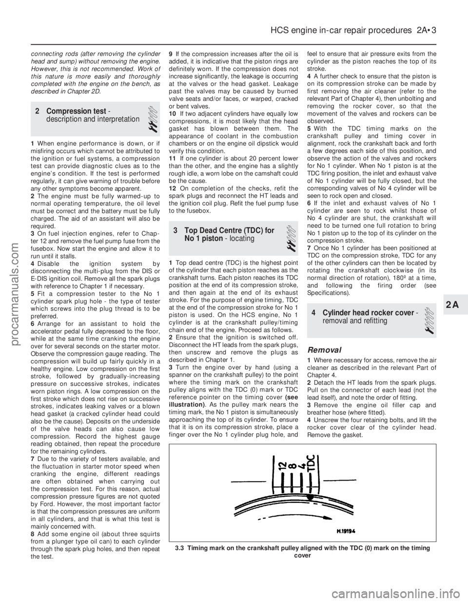
pulley aligns with the TDC (0) mark or TDC
reference pointer on the timing cover (see
illustration) . As the pulley mark nears the
timing mark, the No 1 piston is simultaneously
approaching the top of its cylinder. To ensure
that it is on its compression stroke, place a
finger over the No 1 cylinder plug hole, and feel to ensure that air pressure exits from the
cylinder as the piston reaches the top of its
stroke.
4
A further check to ensure that the piston is
on its compression stroke can be made by
first removing the air cleaner (refer to the
relevant Part of Chapter 4), then unbolting and
removing the rocker cover, so that the
movement of the valves and rockers can be
observed.
5 With the TDC timing marks on the
crankshaft pulley and timing cover in
alignment, rock the crankshaft back and forth
a few degrees each side of this position, and
observe the action of the valves and rockers
for No 1 cylinder. When No 1 piston is at the
TDC firing position, the inlet and exhaust valve
of No 1 cylinder will be fully closed, but the
corresponding valves of No 4 cylinder will be
seen to rock open and closed.
6 If the inlet and exhaust valves of No 1
cylinder are seen to rock whilst those of
No 4 cylinder are shut, the crankshaft will
need to be turned one full rotation to bring
No 1 piston up to the top of its cylinder on the
compression stroke.
7 Once No 1 cylinder has been positioned at
TDC on the compression stroke, TDC for any
of the other cylinders can then be located by
rotating the crankshaft clockwise (in its
normal direction of rotation), 180º at a time,
and following the firing order (see
Specifications).
4 Cylinder head rocker cover -
removal and refitting
1
Removal
1 Where necessary for access, remove the air
cleaner as described in the relevant Part of
Chapter 4.
2 Detach the HT leads from the spark plugs.
Pull on the connector of each lead (not the
lead itself), and note the order of fitting.
3 Remove the engine oil filler cap and
breather hose (where fitted).
4 Unscrew the four retaining bolts, and lift the
rocker cover clear of the cylinder head.
Remove the gasket.
HCS engine in-car repair procedures 2A•3
3.3 Timing mark on the crankshaft pulley aligned with the TDC (0) mar\
k on the timing cover
2A
1595Ford Fiesta Remakeprocarmanuals.com
http://vnx.su
Page 79 of 296
25Unscrew the retaining bolt, and detach
the shift rod stabiliser from the transmission.
As it is detached, note the washer located
between the stabiliser and the transmission.
Tie the stabiliser and the shift rod up out of
the way.
Automatic transmission models
26 Unclip and detach the wiring connector
from the starter inhibitor switch (on the
transmission housing).
27 Referring to the relevant Part of Chapter 4
for details, unhook the accelerator (cam plate)
cable from the carburettor or fuel injection unit
(as applicable) at the transmission end of
the cable. Undo the retaining bolt and
detach the cable sheath bracket from the
transmission. Detach the cam plate cable
from the link.
28 Undo the two nuts from the selector cable
bracket which connects it to the lever on the
selector shaft. Disconnect the yoke from the
lever on the selector shaft and the cable from
the lever.
29 Unscrew the union nuts, and disconnect
the oil cooler feed and return pipes from the
transmission. Allow for a certain amount of
spillage, and plug the connections to prevent
the ingress of dirt.
All models
30 Unscrew the retaining nut and withdraw
the Torx-type clamp bolt securing the lower
suspension arm to the spindle carrier on each
side.
31 Refer to Chapter 10 for details, and
detach the right-hand and left-hand track rod
end balljoints from the spindle carriers.
32 On vehicles fitted with the anti-lock
braking system, refer to Chapter 9 and release
the right-hand modulator from its mounting
bracket without disconnecting the rigid brake
pipes or return hose. Tie the modulator
securely to the bulkhead. Additionally, undo
the three bolts securing the modulator
bracket.
33 Insert a suitable lever between the right-
hand driveshaft inner joint and the
transmission housing, and prise free the
driveshaft from the transmission; be prepared
for oil spillage from the transmission case
through the vacated driveshaft aperture. As it
is being prised free, simultaneously pull the
roadwheel outwards on that side, to enable
the driveshaft inboard end to separate
from the transmission. Once it is free,
suspend and support the driveshaft from the
steering gear, to prevent unnecessary strain
being placed on the driveshaft joints.
34 Insert a suitable plastic plug (or if
available, an old driveshaft joint), into the
transmission driveshaft aperture, to
immobilise the gears of the differential unit.
35 Proceed as described above in
paragraphs 33 and 34, and disconnect the
left-hand driveshaft from the transmission.
36 Connect a suitable lift hoist and sling to
the engine, connecting to the lifting eyes. When securely connected, take the weight of
the engine/transmission unit so that the
tension is relieved from the mountings.
37
Undo the retaining bolts and nuts and
detach the right-hand engine mounting from
the vehicle body.
38 Undo the four bolts securing the
transmission bearer to the underside of the
vehicle body. The transmission bearer is
removed with the engine/transmission
assembly.
39 Unscrew the three retaining bolts, and
remove the auxiliary drivebelt cover from
under the crankshaft pulley.
40 The engine/transmission unit should now
be ready for removal from the vehicle. Check
that all of the associated connections and
fittings are disconnected from the engine and
transmission, and positioned out of the way.
41 Enlist the aid of an assistant to help
steady and guide the power unit down
through the engine compartment as it is
removed. If available, position a suitable
engine trolley or crawler board under the
engine/transmission so that when lowered,
the power unit can be withdrawn from the
front end of the vehicle, and then moved to
the area where it is to be cleaned and
dismantled. On automatic transmission
models, particular care must be taken not to
damage the transmission fluid pan (sump)
during the removal and subsequent refitting
processes.
42 Carefully lower the engine and
transmission unit, ensuring that no fittings
become snagged. Detach the hoist and
remove the power unit from under the vehicle.
43 Referring to the relevant Part of Chapter 7,
separate the transmission from the engine.
44 While the engine/transmission is removed,
check the mountings; renew them if they are
worn or damaged. Similarly, check the
condition of all coolant and vacuum hoses
and pipes (see Chapter 1). Components that
are normally hidden can now be checked
properly, and should be renewed if there is
any doubt at all about their condition. Where
the vehicle is fitted with manual transmission,
take the opportunity to inspect the clutch
components (see Chapter 6). It is regarded by
many as good working practice to renew the
clutch assembly as a matter of course,
whenever major engine overhaul work is
carried out. Check also the condition of all
components (such as the transmission oil
seals) disturbed on removal, and renew any
that are damaged or worn.
Refitting
45 Refitting is a reversal of removal, however
note the following additional points:
a) Refer to the applicable Chapters and Sections as for removal.
b) Fit new spring clips to the grooves in the
inboard end of the right- and left-hand
driveshaft joints. Lubricate the splines
with transmission oil prior to fitting. c) Renew the exhaust flange gasket when
reconnecting the exhaust. Ensure that all
wires are routed clear of the exhaust
system and, on catalytic converter
models, ensure that the heat shields are
securely and correctly fitted.
d) Ensure that all earth lead connections are
clean and securely made.
e) Tighten all nuts and bolts to the specified torque.
f) Fit a new oil filter, and refill the engine and transmission with oil, with reference to
Chapter 1.
g) Refill the cooling system with reference to Chapter 1.
h) Refit the alternator and starter motor with reference to Chapter 5A.
i) Where applicable, refit the power steering pump with reference to Chapter 10.
46 When engine and transmission refitting is
complete, refer to the procedures described
in Section 19 before restarting the engine.
5 Engine/transmission -
removal and refitting
(Zetec engines)
3
Warning: Petrol is extremely
flammable, so take extra
precautions when disconnecting
any part of the fuel system.
Don’t smoke, or allow naked flames or
bare light bulbs, in or near the work area,
and don’t work in a garage where a
natural-gas appliance (such as a clothes
dryer or water heater) is installed. If you
spill petrol on your skin, rinse it off
immediately. Have a fire extinguisher rated
for petrol fires handy, and know how to
use it.
Note: Read through the entire Section, as well
as reading the advice in Section 2, before
beginning this procedure. The engine and
transmission are removed as a unit, lowered to
the ground and removed from underneath,
then separated outside the vehicle.
Removal
1 Park the vehicle on firm, level ground, apply
the handbrake firmly, and slacken the nuts
securing both front roadwheels.
2 Depressurise the fuel system as described
in Chapter 4D.
3 Disconnect the battery negative (earth) lead
(refer to Chapter 5A, Section 1).
4 Place protective covers on the wings, then
remove the bonnet (see Chapter 11).
5 Drain the cooling system and the engine oil
(see Chapter 1).
6 Remove the air inlet components and the
complete air cleaner assembly as described in
Chapter 4D.
7 Equalise the pressure in the fuel tank by
removing the filler cap, then release the fuel
feed and return quick-release couplings, and
pull the hoses off the fuel pipes. Plug or cap
all open fittings.
2D•10 Engine removal and overhaul procedures
1595Ford Fiesta Remakeprocarmanuals.com
http://vnx.su
Page 111 of 296
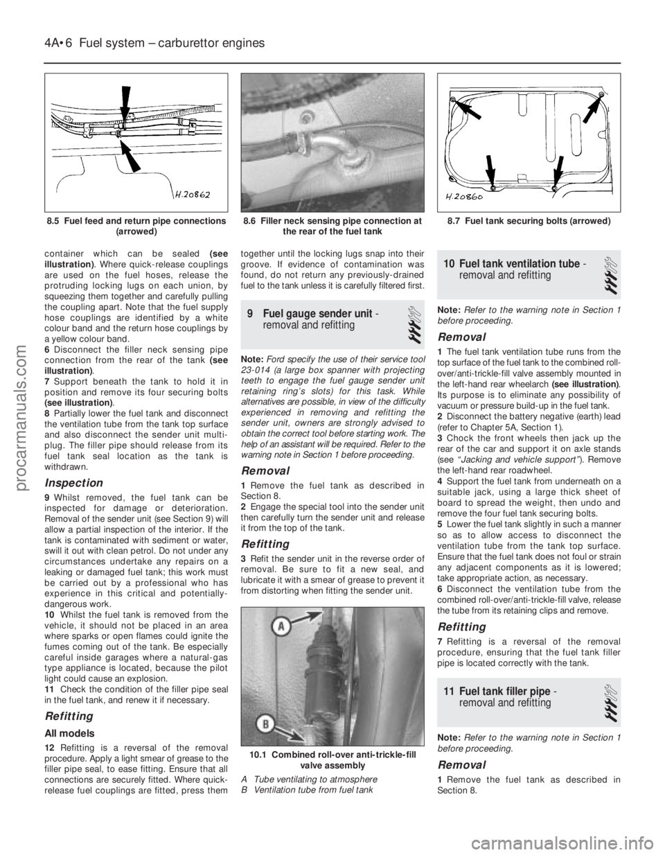
container which can be sealed (see
illustration) . Where quick-release couplings
are used on the fuel hoses, release the
protruding locking lugs on each union, by
squeezing them together and carefully pulling
the coupling apart. Note that the fuel supply
hose couplings are identified by a white
colour band and the return hose couplings by
a yellow colour band.
6 Disconnect the filler neck sensing pipe
connection from the rear of the tank (see
illustration) .
7 Support beneath the tank to hold it in
position and remove its four securing bolts
(see illustration) .
8 Partially lower the fuel tank and disconnect
the ventilation tube from the tank top surface
and also disconnect the sender unit multi-
plug. The filler pipe should release from its
fuel tank seal location as the tank is
withdrawn.
Inspection
9 Whilst removed, the fuel tank can be
inspected for damage or deterioration.
Removal of the sender unit (see Section 9) will
allow a partial inspection of the interior. If the
tank is contaminated with sediment or water,
swill it out with clean petrol. Do not under any
circumstances undertake any repairs on a
leaking or damaged fuel tank; this work must
be carried out by a professional who has
experience in this critical and potentially-
dangerous work.
10 Whilst the fuel tank is removed from the
vehicle, it should not be placed in an area
where sparks or open flames could ignite the
fumes coming out of the tank. Be especially
careful inside garages where a natural-gas
type appliance is located, because the pilot
light could cause an explosion.
11 Check the condition of the filler pipe seal
in the fuel tank, and renew it if necessary.
Refitting
All models
12 Refitting is a reversal of the removal
procedure. Apply a light smear of grease to the
filler pipe seal, to ease fitting. Ensure that all
connections are securely fitted. Where quick-
release fuel couplings are fitted, press them together until the locking lugs snap into their
groove. If evidence of contamination was
found, do not return any previously-drained
fuel to the tank unless it is carefully filtered first.
9
Fuel gauge sender unit -
removal and refitting
3
Note: Ford specify the use of their service tool
23-014 (a large box spanner with projecting
teeth to engage the fuel gauge sender unit
retaining ring’s slots) for this task. While
alternatives are possible, in view of the difficulty
experienced in removing and refitting the
sender unit, owners are strongly advised to
obtain the correct tool before starting work. The
help of an assistant will be required. Refer to the
warning note in Section 1 before proceeding.
Removal
1 Remove the fuel tank as described in
Section 8.
2 Engage the special tool into the sender unit
then carefully turn the sender unit and release
it from the top of the tank.
Refitting
3 Refit the sender unit in the reverse order of
removal. Be sure to fit a new seal, and
lubricate it with a smear of grease to prevent it
from distorting when fitting the sender unit.
10 Fuel tank ventilation tube -
removal and refitting
3
Note: Refer to the warning note in Section 1
before proceeding.
Removal
1 The fuel tank ventilation tube runs from the
top surface of the fuel tank to the combined roll-
over/anti-trickle-fill valve assembly mounted in
the left-hand rear wheelarch (see illustration).
Its purpose is to eliminate any possibility of
vacuum or pressure build-up in the fuel tank.
2 Disconnect the battery negative (earth) lead
(refer to Chapter 5A, Section 1).
3 Chock the front wheels then jack up the
rear of the car and support it on axle stands
(see “Jacking and vehicle support” ). Remove
the left-hand rear roadwheel.
4 Support the fuel tank from underneath on a
suitable jack, using a large thick sheet of
board to spread the weight, then undo and
remove the four fuel tank securing bolts.
5 Lower the fuel tank slightly in such a manner
so as to allow access to disconnect the
ventilation tube from the tank top surface.
Ensure that the fuel tank does not foul or strain
any adjacent components as it is lowered;
take appropriate action, as necessary.
6 Disconnect the ventilation tube from the
combined roll-over/anti-trickle-fill valve, release
the tube from its retaining clips and remove.
Refitting
7 Refitting is a reversal of the removal
procedure, ensuring that the fuel tank filler
pipe is located correctly with the tank.
11 Fuel tank filler pipe -
removal and refitting
3
Note: Refer to the warning note in Section 1
before proceeding.
Removal
1 Remove the fuel tank as described in
Section 8.
4A•6 Fuel system – carburettor engines
10.1 Combined roll-over anti-trickle-fill valve assembly
A Tube ventilating to atmosphere
B Ventilation tube from fuel tank
8.7 Fuel tank securing bolts (arrowed)8.6 Filler neck sensing pipe connection at the rear of the fuel tank
1595Ford Fiesta Remake
8.5 Fuel feed and return pipe connections
(arrowed)procarmanuals.com
http://vnx.su
Page 120 of 296
16Prise out the tamperproof seal covering
the fuel mixture screw, then undo and remove
the mixture screw.
Cleaning and inspection
17 Wash the carburettor components,
drillings and passages with clean petrol, then
blow them dry using a low-pressure air line. A
high-pressure air line must not be applied to
the accelerator pump discharge assembly or
the pump supply valve, as they each contain a
rubber Vernay valve, and these can easily be
damaged under high pressure. Never use a
piece of wire for cleaning purposes.
18 Examine all of the carburettor
components for signs of damage or wear,
paying particular attention to the diaphragms,
throttle spindle and plates, needle valve and
mixture screw; the power valve jet is adjacent
to the primary main jet. Renew all
diaphragms, sealing washers and gaskets as
a matter of course.
Reassembly
19 Refit the fuel mixture screw by fully
winding the screw in, then unwinding three
turns to give an approximate setting.
20 Refit the power valve assembly ensuring
that the diaphragm lies flat, and that the
vacuum gallery lines up correctly with the
diaphragm and housing.
21 Reassemble the secondary barrel
diaphragm into its housing, ensuring that
the diaphragm lies flat and that the vacuum
gallery lines up with the diaphragm and
housing. Also, to assist with installation, do
not reconnect its operating rod until the cover
has been secured.
22 Refit the throttle kicker mounting bracket.
23 Refit the anti-dieseling (fuel cut-off)
solenoid, using a new sealing washer.
24 Refit the accelerator pump assembly,
ensuring that the diaphragm lies flat and is not
kinked.
25 Reassemble the throttle kicker, ensuring
that the diaphragm lies flat and that the relative position of the diaphragm operating
link to the throttle kicker cover is correct. Fully
attach the throttle kicker assembly.
26
Refit the main and idle jets, making
reference to the notes taken during
dismantling to ensure correct fitted locations.
27 Reassemble the carburettor upper body
as described in the following paragraphs.
28 Refit the needle valve housing (using a
new washer if applicable).
29 Refit the needle valve and float assembly,
having ensured that the float tag locates
below the spring clip on the needle valve.
Insert the float retaining pin to secure.
30 Adjust the float level as follows. Ensuring
that a new gasket is fitted to the carburettor
upper body, hold the upper body in the
vertical position; the needle valve must be
shut off. Measure the distance shown (see
illustration) , and adjust by bending the float
tag if the measurement is outside the
specification. Recheck the float level
adjustment after bending the float tag, as
necessary.
31 Refit the choke pull-down diaphragm,
ensuring that the diaphragm lies flat and that
the vacuum gallery lines up correctly with the
diaphragm and housing (see illustration).
32 Adjust the choke pull-down as follows.
Fully close the choke, then manually push the
diaphragm operating rod up to its stop;
measure the distance between the
downdraught side of the choke plate and the
venturi, using a gauge rod or the shank of a
twist drill bit (of known size). If the
measurement is outside specification, remove
the tamperproof seal from the housing, and
adjust the now revealed adjustment screw
accordingly. Fit a new tamperproof seal after
successful adjustment.
33 Refit the fuel feed filter, and secure with
its brass nut and sealing washer.
34 Refit the carburettor upper body to the
carburettor main body, ensuring that its new
gasket seats correctly and that the float does
not foul during assembly. Insert and tighten
the securing screws. 35
Reconnect any vacuum pipes removed
during dismantling (where applicable).
36 On completion, refit the carburettor as
described in Section 28. Where applicable,
check and adjust the throttle kicker setting
(Section 27) after adjusting the idle speed and
mixture settings.
30 Carburettor (Weber TLD) -
description
This carburettor incorporates many of the
features of the TLDM type described in
Section 18. The main differences are that a
throttle kicker is not used, the secondary
venturi (barrel) is vacuum-operated, and that a
coolant-heated automatic choke control
system is fitted. The choke system is fully automatic. When
the engine is cold, the bi-metal spring which
controls the position of the choke plate is fully
wound up, and holds the plate closed. As the
engine warms up, the bi-metal spring is
heated by the coolant and begins to unwind,
thereby progressively opening the choke
plate. A vacuum-operated pull-down
mechanism controls the choke plate under
certain operating conditions, and an internal
fast-idle system is incorporated. Idle speed and mixture adjustment
procedures are described in Chapter 1, but it
is important to note that accurate adjustments
can only be made using the necessary
equipment.
31 Carburettor (Weber TLD) -
fast-idle speed adjustment
4
Note: Before carrying out any carburettor
adjustments, ensure that the spark plug gaps
are set as specified, and that all electrical and
vacuum connections are secure. To carry out
checks and adjustments, an accurate
Fuel system – carburettor engines 4A•15
29.31 Exploded view of the choke pull-down assembly (Weber DFTM carbur\
ettor)
A Housing B Diaphragm
29.30 Float level adjustment (Weber DFTMcarburettor)
A Float level setting dimension
B Adjusting tag
4A
1595Ford Fiesta Remakeprocarmanuals.com
http://vnx.su
Page 139 of 296
13Detach the fuel injectors from the fuel rail,
then remove the upper and lower seal from
each injector (see illustration) . All seals must
be renewed (even if only one injector is to be
renewed).
14 Prior to refitting the injectors, ensure that
all mating surfaces are perfectly clean.
Lubricate the new injector seals with clean
engine oil to ease their assembly to the
injectors.
15 Refitting is a reversal of the removal
procedure. Refer to the Specificationsat the
start of this Chapter for the tightening torques.
When refitting the fuel rail, ensure that the
injectors are correctly located. Ensure that the
mating surfaces of the throttle housing are
perfectly clean before assembling.
16 On completion, restart the engine and
check the various fuel connections for any
signs of leaks.
Fuel pressure regulator
17 Relieve the residual pressure in the fuel
system (see Section 2), and equalise tank
pressure by removing the fuel filler cap. Warning: This procedure will
merely relieve the increased
pressure necessary for the
engine to run - remember that
fuel will still be present in the system
components, and take precautions
accordingly before disconnecting any of
them.
18 Disconnect the battery negative (earth)
lead (refer to Chapter 5A, Section 1). 19
Release the fuel return pipe securing clip,
and detach the pipe from the regulator.
20 Pull free the vacuum pipe from the
regulator connector (see illustration).
21 Unscrew the two retaining bolts and
remove the regulator. Remove the old sealing
ring for renewal.
22 Refit in the reverse order of removal.
Lubricate the new seal ring with clean engine oil
to ease assembly. When the regulator is refitted
and the fuel and vacuum lines are reconnected,
turn the ignition on and off five times (without
cranking the engine) and check for any sign of
fuel leaks before restarting the engine.
Idle speed control valve
Note: The idle speed control valve may be
mounted on the air cleaner, on the engine
compartment bulkhead, or on the side of the
inlet manifold according to valve make and
year of manufacture. Valves manufactured by
Weber are mounted on the air cleaner and
require periodic maintenance (see Chapter 1).
Bulkhead and inlet manifold mounted valves
are manufactured by Hitachi and are
maintenance free.
23 Disconnect the battery negative (earth)
lead (refer to Chapter 5A, Section 1).
24 Disconnect the valve’s wiring multiplug
(see illustration) .
25 Where applicable disconnect the air
hose(s) from the valve.
26 Undo the two or four bolts (according to
type), and remove the valve from the air
cleaner, bulkhead or inlet manifold. 27
Refitting is a reversal of the removal
procedure. Ensure that the mating faces are
clean before reassembling.
28 When the valve is refitted, restart the
engine and check that there are no induction
leaks. Run the engine until its normal
operating temperature is reached, and check
that the idle speed is stable. Stop the engine,
connect up a tachometer in accordance with
its maker’s instructions, then restart the
engine and check that the idle speed is as
specified with all electrical items (lights, heater
blower motor, etc) switched off, then on. The
idle speed should remain the same. Switch off
the electrical items, turn the engine off and
detach the tachometer to complete the test.
Throttle housing
29 Disconnect the battery negative (earth)
lead (refer to Chapter 5A, Section 1).
30 Disconnect the ignition HT lead
connectors from the spark plugs, and release
the leads from their locating grooves in the air
inlet duct. Position them out of the way.
31 Remove the air inlet components as
described in Section 4.
32 Unscrew the retaining nuts and the bolt,
and detach the accelerator cable support
bracket at the throttle housing.
33 Disconnect the wiring connector from the
throttle position sensor.
34 Unscrew the four retaining bolts, and
remove the throttle housing and its mating
face gasket (see illustration 14.7) .
35 Refit in the reverse order of removal.
Check that the mating faces are clean, and fit
a new gasket.
EEC IV engine management
module
Note: The module is fragile. Take care not to
drop it, or subject it to any other kind of
impact. Do not subject it to extremes of
temperature, or allow it to get wet. Refer to
Part B, Section 14 for illustrations of the
following procedure.
36 Disconnect the battery negative (earth)
lead (refer to Chapter 5A, Section 1).
37 Unscrew and remove the two nuts
securing the module cover in the engine
compartment, then carefully draw the cover
away from its location. Unscrew the module
multi-plug retaining bolt and disconnect
the multi-plug from the module.
38 The aid of an assistant will be required at
this stage, to support and withdraw the
module from inside the passenger
compartment as its mounting bracket retaining
tags are compressed and released from the
engine compartment. Do not allow the module
to drop into the passenger compartment as
irreparable damage is likely to result. The
module may be separated from its mounting
bracket by undoing the securing bolts.
39 Refitting is a reversal of the removal
procedure, ensuring that the module
mounting bracket retaining tags are felt to
snap into position
4C•6 Fuel system - electronic fuel injection engines
14.24 Disconnect the multi-plug from the idle speed control valve. Upper valve
retaining bolt (arrowed)14.20 Fuel pressure regulator showingvacuum pipe (A) and fuel return pipe
connection (B)
14.13 Remove the seals from the injectors14.12b . . . and withdraw the fuel rail and injectors
1595Ford Fiesta Remakeprocarmanuals.com
http://vnx.su
Page 146 of 296
4 Air cleaner assembly and airinlet components - removal
and refitting
1
Air cleaner assembly
1 Disconnect the battery negative (earth) lead
(refer to Chapter 5A, Section 1).
2 Disconnect the mass air flow sensor wiring
multi-plug, then release the clips and
withdraw the sensor, complete with inlet
hose, from the air cleaner cover (see
illustrations) . Carefully position the mass air
flow sensor and hose assembly to one side.
3 Detach the fresh air inlet duct from the air
cleaner housing.
4 Unscrew the air cleaner housing retaining
nut, then pull the housing upwards to release
the locating pegs from their rubber grommets.
As the housing is withdrawn, detach the
crankcase breather hose (see illustration).
Remove the assembly from the car.
5 Refitting is the reverse of the removal
procedure. Ensure that the housing pegs seat
fully in their grommets, and that the mass air
flow sensor is correctly located.
Air inlet components
6 On PTE engines, disconnect the HT leads
from the spark plugs, labelling them if
necessary to avoid confusion on refitting.
7 Slacken the hose clip, and detach the flexible air inlet hose from the mass air flow
sensor.
8
On PTE engines, disconnect the ventilation
hose from the inlet duct over the top of the
engine.
9 On PTE engines undo the two inlet duct
retaining bolts; On Zetec engines , undo the
two bolts and lift off the air inlet duct retaining
strap (see illustration) . Withdraw the inlet
duct from the throttle housing and remove the
duct and flexible hose from the engine.
10 Refitting is the reverse of the removal
procedure.
5 Accelerator cable - removal,
refitting and adjustment
1
Removal
1 Disconnect the battery negative (earth) lead
(refer to Chapter 5A, Section 1).
2 Fold back the carpet and insulation in the
driver’s footwell to gain access to the
accelerator pedal.
3 Detach the accelerator cable from the
pedal.
4 From within the engine compartment,
detach the outer cable from the
adjuster/support bracket by removing the
metal retaining clip (see illustration).5
Pivot the throttle quadrant by hand, detach
the inner cable nipple from the throttle lever
and remove the cable.
Refitting
6 Refit in the reverse order of removal. When
the cable is reconnected at each end, adjust
the cable as follows.
Adjustment
7 Remove the outer cable metal retaining clip
at the adjuster/support bracket and lubricate
the cable adjuster grommet with soapy water.
8 Remove any slack by pulling the cable
outer as far as possible out of the adjuster.
Have an assistant depress the accelerator
pedal fully - the cable outer will move back
into the adjuster - and hold it there while the
clip is refitted.
9 Check that the throttle quadrant moves
smoothly and easily from the fully-closed to
the fully-open position and back again as the
assistant depresses and releases the
accelerator pedal. Re-adjust the cable if
required.
6 Accelerator pedal -
removal and refitting
1
Refer to Part A, Section 5.
Fuel system - sequential electronic fuel injection engines 4D•3
4.2c . . . and withdraw the sensor4.2b . . . release the retaining clips . . .4.2a Disconnect the mass air flow sensor
wiring multi-plug . . .
5.4 Detach the accelerator outer cableretaining clip (arrowed)4.9 Unscrew the nuts (arrowed) to releasethe air intake duct on Zetec engines4.4 Unscrew front retaining nut and lift theair cleaner housing, disconnecting the
breather hose (arrowed)
4D
1595Ford Fiesta Remakeprocarmanuals.com
http://vnx.su
Page 185 of 296
13 Hydraulic system- bleeding
(conventional braking system)
3
Note: For vehicles equipped with an anti-lock
braking system, refer to Section 14. Warning: Hydraulic fluid is
poisonous; wash off
immediately and thoroughly in
the case of skin contact, and
seek immediate medical advice if any fluid
is swallowed or gets into the eyes. Certain
types of hydraulic fluid are inflammable,
and may ignite when allowed into contact
with hot components; when servicing any
hydraulic system, it is safest to assume
that the fluid IS inflammable, and to take
precautions against the risk of fire as
though it is petrol that is being handled.
Hydraulic fluid is also an effective paint
stripper, and will attack plastics; if any is
spilt, it should be washed off immediately,
using copious quantities of clean water.
Finally, it is hygroscopic (it absorbs
moisture from the air). The more moisture
is absorbed by the fluid, the lower its
boiling point becomes, leading to a
dangerous loss of braking under hard use.
Old fluid may be contaminated and unfit
for further use. When topping-up or
renewing the fluid, always use the
recommended type, and ensure that it
comes from a freshly-opened sealed
container.
1 The correct operation of any hydraulic
system is only possible after removing all air
from the components and circuit; and this is
achieved by bleeding the system.
2 During the bleeding procedure, add only
clean, unused hydraulic fluid of the
recommended type; never re-use fluid that
has already been bled from the system.
Ensure that sufficient fluid is available before
starting work.
3 If there is any possibility of incorrect fluid
being already in the system, the brake
components and circuit must be flushed
completely with uncontaminated, correct
fluid, and new seals should be fitted
throughout the system.
4 If hydraulic fluid has been lost from the
system, or air has entered because of a leak,
ensure that the fault is cured before
proceeding further.
5 Park the vehicle on level ground, and apply
the handbrake. Switch off the engine, then
(where applicable) depress the brake pedal
several times to dissipate the vacuum from
the servo unit. Note:When bleeding the
system, the vehicle must maintain a level
attitude, ie not tilted in any manner, to ensure
that air is not trapped within the pressure
control valves. During certain operations in
this manual, instructions are given to bleed the
brake hydraulic system with the front or the
rear of the vehicle raised. In such cases raise
the rest of the vehicle so that it maintains a level attitude, but only if it is safe to do so. If it
is not possible to achieve this safely, complete
the remainder of the operation and bleed the
brake hydraulic system with the vehicle on its
wheels.
6
Check that all pipes and hoses are secure,
unions tight and bleed screws closed.
Remove the dust caps (where applicable), and
clean any dirt from around the bleed screws.
7 Disconnect the wiring multi-plug from the
fluid level warning indicator in the master
cylinder reservoir filler cap, then remove the
filler cap. Note that the filler cap must not be
inverted. Top-up the reservoir with the
specified fluid to the “Maximum” level (see
“Weekly Checks” ). Remember to maintain the
fluid level at least above the “Minimum” level
line throughout the procedure, otherwise
there is a risk of further air entering the
system.
8 There are a number of one-man, do-it-
yourself brake bleeding kits currently available
from motor accessory shops. It is
recommended that one of these kits is used
whenever possible, as they greatly simplify
the bleeding operation, and also reduce the
risk of expelled air and fluid being drawn back
into the system. If such a kit is not available,
the basic (two-man) method must be used,
which is described in detail below.
9 If a kit is to be used, prepare the vehicle as
described previously, and follow the kit
manufacturer’s instructions, as the procedure
may vary slightly according to the type being
used; generally, they are as outlined below in
the relevant sub-section.
10 Whichever method is used, the same
sequence must be followed (paragraphs 11
and 12) to ensure the removal of all air from
the system.
Bleeding sequence
11 If the system has been only partially
disconnected, and suitable precautions were
taken to minimise fluid loss, it should be
necessary to bleed only that part of the
system (ie the primary or secondary circuit).
12 If the complete system is to be bled, then
it is suggested that you work in the following
sequence: a) Right-hand front wheel.
b) Left-hand rear wheel.
c) Left-hand front wheel.
d) Right-hand rear wheel.
Bleeding - basic (two-man)
method
13 Collect a clean glass jar, a suitable length
of plastic or rubber tubing which is a tight fit
over the bleed screw, and a ring spanner to fit
the screw. The help of an assistant will also be
required.
14 Remove the dust cap from the first screw
in the sequence (if not already done). Fit a
suitable spanner and tube to the screw, place
the other end of the tube in the jar, and pour in
sufficient fluid to cover the end of the tube.
15 Ensure that the master cylinder reservoir fluid level is maintained at least above the
“Minimum” level throughout the procedure.
16
Have the assistant fully depress the brake
pedal several times to build up pressure, then
maintain it down on the final downstroke.
17 While pedal pressure is maintained,
unscrew the bleed screw (approximately one
turn) and allow the compressed fluid and air to
flow into the jar. The assistant should maintain
pedal pressure, following the pedal down to
the floor if necessary, and should not
release the pedal until instructed to do so.
When the flow stops, tighten the bleed screw
again. Have the assistant release the pedal
slowly, and recheck the reservoir fluid level.
18 Repeat the steps given in paragraphs 16
and 17 until the fluid emerging from the bleed
screw is free from air bubbles. If the master
cylinder has been drained and refilled, and air
is being bled from the first screw in the
sequence, allow at least five seconds between
cycles for the master cylinder passages to refill.
19 When no more air bubbles appear, tighten
the bleed screw securely, remove the tube
and spanner, and refit the dust cap (where
applicable). Do not overtighten the bleed
screw.
20 Repeat the procedure on the remaining
screws in the sequence, until all air is
removed from the system and the brake pedal
feels firm again.
Bleeding - using a one-way
valve kit
21 As their name implies, these kits consist of
a length of tubing with a one-way valve fitted,
to prevent expelled air and fluid being drawn
back into the system; some kits include a
translucent container, which can be positioned
so that the air bubbles can be more easily
seen flowing from the end of the tube.
22 The kit is connected to the bleed screw,
which is then opened (see illustration). The
user returns to the driver’s seat, depresses
the brake pedal with a smooth, steady stroke,
and slowly releases it; this is repeated until
the expelled fluid is clear of air bubbles.
23 Note that these kits simplify work so
much that it is easy to forget the master
cylinder reservoir fluid level; ensure that this is
maintained at least above the “Minimum” level
at all times.
9•10 Braking system
13.22 Bleeding the hydraulic system using a one-way valve kit
1595Ford Fiesta Remakeprocarmanuals.com
http://vnx.su