1989 FORD FIESTA open gas tank
[x] Cancel search: open gas tankPage 79 of 296
25Unscrew the retaining bolt, and detach
the shift rod stabiliser from the transmission.
As it is detached, note the washer located
between the stabiliser and the transmission.
Tie the stabiliser and the shift rod up out of
the way.
Automatic transmission models
26 Unclip and detach the wiring connector
from the starter inhibitor switch (on the
transmission housing).
27 Referring to the relevant Part of Chapter 4
for details, unhook the accelerator (cam plate)
cable from the carburettor or fuel injection unit
(as applicable) at the transmission end of
the cable. Undo the retaining bolt and
detach the cable sheath bracket from the
transmission. Detach the cam plate cable
from the link.
28 Undo the two nuts from the selector cable
bracket which connects it to the lever on the
selector shaft. Disconnect the yoke from the
lever on the selector shaft and the cable from
the lever.
29 Unscrew the union nuts, and disconnect
the oil cooler feed and return pipes from the
transmission. Allow for a certain amount of
spillage, and plug the connections to prevent
the ingress of dirt.
All models
30 Unscrew the retaining nut and withdraw
the Torx-type clamp bolt securing the lower
suspension arm to the spindle carrier on each
side.
31 Refer to Chapter 10 for details, and
detach the right-hand and left-hand track rod
end balljoints from the spindle carriers.
32 On vehicles fitted with the anti-lock
braking system, refer to Chapter 9 and release
the right-hand modulator from its mounting
bracket without disconnecting the rigid brake
pipes or return hose. Tie the modulator
securely to the bulkhead. Additionally, undo
the three bolts securing the modulator
bracket.
33 Insert a suitable lever between the right-
hand driveshaft inner joint and the
transmission housing, and prise free the
driveshaft from the transmission; be prepared
for oil spillage from the transmission case
through the vacated driveshaft aperture. As it
is being prised free, simultaneously pull the
roadwheel outwards on that side, to enable
the driveshaft inboard end to separate
from the transmission. Once it is free,
suspend and support the driveshaft from the
steering gear, to prevent unnecessary strain
being placed on the driveshaft joints.
34 Insert a suitable plastic plug (or if
available, an old driveshaft joint), into the
transmission driveshaft aperture, to
immobilise the gears of the differential unit.
35 Proceed as described above in
paragraphs 33 and 34, and disconnect the
left-hand driveshaft from the transmission.
36 Connect a suitable lift hoist and sling to
the engine, connecting to the lifting eyes. When securely connected, take the weight of
the engine/transmission unit so that the
tension is relieved from the mountings.
37
Undo the retaining bolts and nuts and
detach the right-hand engine mounting from
the vehicle body.
38 Undo the four bolts securing the
transmission bearer to the underside of the
vehicle body. The transmission bearer is
removed with the engine/transmission
assembly.
39 Unscrew the three retaining bolts, and
remove the auxiliary drivebelt cover from
under the crankshaft pulley.
40 The engine/transmission unit should now
be ready for removal from the vehicle. Check
that all of the associated connections and
fittings are disconnected from the engine and
transmission, and positioned out of the way.
41 Enlist the aid of an assistant to help
steady and guide the power unit down
through the engine compartment as it is
removed. If available, position a suitable
engine trolley or crawler board under the
engine/transmission so that when lowered,
the power unit can be withdrawn from the
front end of the vehicle, and then moved to
the area where it is to be cleaned and
dismantled. On automatic transmission
models, particular care must be taken not to
damage the transmission fluid pan (sump)
during the removal and subsequent refitting
processes.
42 Carefully lower the engine and
transmission unit, ensuring that no fittings
become snagged. Detach the hoist and
remove the power unit from under the vehicle.
43 Referring to the relevant Part of Chapter 7,
separate the transmission from the engine.
44 While the engine/transmission is removed,
check the mountings; renew them if they are
worn or damaged. Similarly, check the
condition of all coolant and vacuum hoses
and pipes (see Chapter 1). Components that
are normally hidden can now be checked
properly, and should be renewed if there is
any doubt at all about their condition. Where
the vehicle is fitted with manual transmission,
take the opportunity to inspect the clutch
components (see Chapter 6). It is regarded by
many as good working practice to renew the
clutch assembly as a matter of course,
whenever major engine overhaul work is
carried out. Check also the condition of all
components (such as the transmission oil
seals) disturbed on removal, and renew any
that are damaged or worn.
Refitting
45 Refitting is a reversal of removal, however
note the following additional points:
a) Refer to the applicable Chapters and Sections as for removal.
b) Fit new spring clips to the grooves in the
inboard end of the right- and left-hand
driveshaft joints. Lubricate the splines
with transmission oil prior to fitting. c) Renew the exhaust flange gasket when
reconnecting the exhaust. Ensure that all
wires are routed clear of the exhaust
system and, on catalytic converter
models, ensure that the heat shields are
securely and correctly fitted.
d) Ensure that all earth lead connections are
clean and securely made.
e) Tighten all nuts and bolts to the specified torque.
f) Fit a new oil filter, and refill the engine and transmission with oil, with reference to
Chapter 1.
g) Refill the cooling system with reference to Chapter 1.
h) Refit the alternator and starter motor with reference to Chapter 5A.
i) Where applicable, refit the power steering pump with reference to Chapter 10.
46 When engine and transmission refitting is
complete, refer to the procedures described
in Section 19 before restarting the engine.
5 Engine/transmission -
removal and refitting
(Zetec engines)
3
Warning: Petrol is extremely
flammable, so take extra
precautions when disconnecting
any part of the fuel system.
Don’t smoke, or allow naked flames or
bare light bulbs, in or near the work area,
and don’t work in a garage where a
natural-gas appliance (such as a clothes
dryer or water heater) is installed. If you
spill petrol on your skin, rinse it off
immediately. Have a fire extinguisher rated
for petrol fires handy, and know how to
use it.
Note: Read through the entire Section, as well
as reading the advice in Section 2, before
beginning this procedure. The engine and
transmission are removed as a unit, lowered to
the ground and removed from underneath,
then separated outside the vehicle.
Removal
1 Park the vehicle on firm, level ground, apply
the handbrake firmly, and slacken the nuts
securing both front roadwheels.
2 Depressurise the fuel system as described
in Chapter 4D.
3 Disconnect the battery negative (earth) lead
(refer to Chapter 5A, Section 1).
4 Place protective covers on the wings, then
remove the bonnet (see Chapter 11).
5 Drain the cooling system and the engine oil
(see Chapter 1).
6 Remove the air inlet components and the
complete air cleaner assembly as described in
Chapter 4D.
7 Equalise the pressure in the fuel tank by
removing the filler cap, then release the fuel
feed and return quick-release couplings, and
pull the hoses off the fuel pipes. Plug or cap
all open fittings.
2D•10 Engine removal and overhaul procedures
1595Ford Fiesta Remakeprocarmanuals.com
http://vnx.su
Page 98 of 296
Before adding antifreeze, check all hoses
and hose connections, because antifreeze
tends to leak through very small openings.
Engines don’t normally consume coolant, so if
the level falls regularly, find the cause and
correct it. The exact mixture of antifreeze-to-water
which you should use depends on the relative
weather conditions. The mixture should
contain at least 40% antifreeze, but not more
than 70%. Consult the mixture ratio chart on
the antifreeze container before adding
coolant. Hydrometers are available at most
automotive accessory shops to test the
coolant. Use only good-quality ethylene-
glycol-based antifreeze which meets the
vehicle manufacturer’s specifications.
3 Cooling system hoses -
disconnection and renewal
1
Note: Refer to the warnings given in Section 1
of this Chapter before starting work.
1 If the checks described in Chapter 1 reveal
a faulty hose, it must be renewed as follows.
2 First drain the cooling system (see Chap-
ter 1); if the antifreeze is not due for renewal,
the drained coolant may be re-used, if it is
collected in a clean container.
3 To disconnect any hose, use a pair of pliers
to release the spring clamps (or a screwdriver
to slacken screw-type clamps), then move
them along the hose clear of the union.
Carefully work the hose off its stubs. The
hoses can be removed with relative ease
when new - on an older car, they may have
stuck.
4 If a hose proves stubborn, try to release it
by rotating it on its unions before attempting
to work it off. Gently prise the end of the hose
with a blunt instrument (such as a flat-bladed
screwdriver), but do not apply too much force,
and take care not to damage the pipe stubs or
hoses. Note in particular that the radiator hose
unions are fragile; do not use excessive force
when attempting to remove the hoses.
5 When refitting a hose, first slide the clamps
onto the hose, then work the hose onto its
unions. 6
Work each hose end fully onto its union,
then check that the hose is settled correctly
and is properly routed. Slide each clip along
the hose until it is behind the union flared end,
before tightening it securely.
7 Refill the system with coolant (see Chap-
ter 1).
8 Check carefully for leaks as soon as
possible after disturbing any part of the
cooling system.
4 Thermostat -
removal, testing and refitting
1
Note: Refer to the warnings given in Section 1
of this Chapter before starting work.
Removal
1 Disconnect the battery negative (earth) lead
(refer to Chapter 5A, Section 1).
2 Drain the cooling system (see Chapter 1).
3 Refer to the relevant Part of Chapter 4 and
remove the air cleaner or air inlet hoses,
according to engine type as necessary, to
gain access to the thermostat housing.
HCS, CVH and PTE engines
4 Loosen the clips, and disconnect the
radiator top hose, expansion tank hose and,
where applicable, the heater hose from the
thermostat housing (see illustrations).5
Disconnect the thermostatic switch wire
multi-plug from the thermostat housing.
6 Unscrew the retaining bolts, and remove
the thermostat housing (see illustration).
7 Remove the gasket from the mating face of
the thermostat housing, then using suitable
pliers, compress the thermostat retaining clip
(where applicable) and remove it from the
housing. Extract the thermostat from
the housing (noting its direction of fitting) and
where applicable, remove the O-ring seal (see
illustrations) .
Zetec engines
8Disconnect the expansion tank hose and
Cooling, heating and ventilation systems 3•3
4.4b Disconnecting the expansion tank
top hose from the thermostat housing
(HCS engine). Radiator cooling fan thermal switch (arrowed)4.4a Thermostat housing hose
attachments on the CVH engine
4.7b Exploded view of thermostat and housing (CVH and PTE engines)
A Sealing ring C Retaining clip
B Thermostat
4.7a Removing the gasket and thermostat from an HCS engine4.6 Removing the thermostat housingfrom a CVH engine
3
1595Ford Fiesta Remake
If all else fails, cut the hose
with a sharp knife, then slit
it so that it can be peeled off
in two pieces. Although this
may prove expensive if the hose is
otherwise undamaged, it is preferable
to buying a new radiator.
If the hose is stiff, use a little
soapy water as a lubricant,
or soften the hose by
soaking it in hot water. Do
not use oil or grease, which may attack
the rubber.
procarmanuals.com
http://vnx.su
Page 110 of 296
position at the carburettor, then secure the
outer cable with its retaining clip.
Adjustment
12To check that the choke cable is correctly
adjusted, the control knob must be pulled out
to the full-on position and the choke lever
must be in contact with its stop. Adjust as
required if necessary.
13 Press the choke knob fully in (to the off
position), then check that the choke linkage at
the carburettor has fully returned to its off
position and the choke valve plate in the
carburettor is at a right angle (90º) to the
venturi.
14 Refit the air cleaner.
15 Reconnect the battery, turn the ignition
on, operate the choke and check that the
choke warning light operates correctly.
7 Fuel pump -
testing, removal and refitting
2
Note: Refer to the warning note in Section 1
before proceeding.
Testing
1 Access to the fuel pump on HCS engine models is best gained from underneath the
vehicle
(see illustrations) . Apply the
handbrake, then raise and support it on axle
stands at the front end (see “Jacking and
vehicle support” ).
2 The fuel pump may be tested by
disconnecting the fuel feed pipe from the
carburettor, and placing the pipe’s open end
in a suitable container.
3 Detach the multi-plug from the DIS ignition
coil, or the LT lead from the negative terminal
of the ignition coil, to prevent the engine from
firing.
4 Actuate the starter motor. If the fuel pump
is in good working order, regular well-defined
spurts of fuel should eject from the open end
of the disconnected fuel pipe.
5 If this does not occur, and there is fuel in
the tank, the pump is defective and must be
renewed. The fuel pump is a sealed unit, and
cannot be repaired.
Removal
6 Two types of mechanical fuel pump are
fitted, the application depending on the
engine type. Some models may also be fitted
with a fuel vapour separator (see illustration) ;
if this is removed, its hoses should be labelled
to avoid the possibility of confusion and
incorrect attachment on refitting. 7
To remove the fuel pump, first disconnect
the battery negative (earth) lead (refer to
Chapter 5A, Section 1).
8 Where applicable, remove the air cleaner to
improve access to the fuel pump (see Sec-
tion 2).
9 Disconnect the fuel hoses from the fuel
pump, noting their respective connections for
refitting. Where quick-release couplings are
used on the fuel hoses, release the protruding
locking lugs on each union, by squeezing
them together and carefully pulling the
coupling apart. Use rag to soak up any spilt
fuel. Where the unions are colour-coded, the
pipes cannot be confused. Where both unions
are the same colour, note carefully which pipe
is connected to which, and ensure that they
are correctly reconnected on refitting. Plug
the hoses to prevent fuel spillage and the
ingress of dirt.
10 Unscrew and remove the retaining bolts
or nuts (as applicable) and remove the fuel
pump.
11 Recover the gasket/spacer (see
illustration) and if required, withdraw the
pump operating pushrod (CVH engines only).
12 Thoroughly clean the mating faces on the
pump and engine.
Refitting
13 Refit in the reverse order of removal. Be
sure to use a new gasket, and tighten the
securing bolts/nuts securely. Ensure that the
hoses are correctly and securely reconnected.
If they were originally secured with crimped
type hose clips, discard them and fit
screw type clips. Where quick-release
couplings are fitted, press them together until
the locking lugs snap into their groove.
14 When the engine is restarted, check
the pump connections for any signs of fuel
leaks.
8 Fuel tank - removal,
inspection and refitting
3
Note: Refer to the warning note in Section 1
before proceeding.
Removal
1 Run the fuel level as low as possible prior to
removing the tank.
2 Disconnect the battery negative (earth) lead
(refer to Chapter 5A, Section 1).
3 Remove the fuel filler cap, then syphon or
pump out the remaining fuel from the fuel tank
(there is no drain plug). The fuel must be
emptied into a suitable container for storage.
4 Chock the front wheels then jack up the
rear of the car and support it on axle stands
(see “Jacking and vehicle support” ). Remove
the rear roadwheels.
5 Unclip and disconnect the fuel feed and
return hoses located in front of the fuel tank,
and allow any residual fuel to drain into a
Fuel system – carburettor engines 4A•5
7.6 Fuel pump and fuel vapour separator
arrangement on HCS engine (shown from
below)
7.1b Fuel pump assembly fitted to CVHengines (securing nuts arrowed)
A Fuel feed from tank
B Fuel return to tank
C Fuel feed to carburettor7.1a Fuel pump location on HCS engine (shown from below)
A Fuel inlet hose
B Fuel return hose to tank
C Fuel outlet hose to carburettor
D Pump securing bolts
7.11 Gasket/spacer fitment on HCS
engine. Note position of the lug (arrowed)
4A
1595Ford Fiesta Remakeprocarmanuals.com
http://vnx.su
Page 111 of 296
container which can be sealed (see
illustration) . Where quick-release couplings
are used on the fuel hoses, release the
protruding locking lugs on each union, by
squeezing them together and carefully pulling
the coupling apart. Note that the fuel supply
hose couplings are identified by a white
colour band and the return hose couplings by
a yellow colour band.
6 Disconnect the filler neck sensing pipe
connection from the rear of the tank (see
illustration) .
7 Support beneath the tank to hold it in
position and remove its four securing bolts
(see illustration) .
8 Partially lower the fuel tank and disconnect
the ventilation tube from the tank top surface
and also disconnect the sender unit multi-
plug. The filler pipe should release from its
fuel tank seal location as the tank is
withdrawn.
Inspection
9 Whilst removed, the fuel tank can be
inspected for damage or deterioration.
Removal of the sender unit (see Section 9) will
allow a partial inspection of the interior. If the
tank is contaminated with sediment or water,
swill it out with clean petrol. Do not under any
circumstances undertake any repairs on a
leaking or damaged fuel tank; this work must
be carried out by a professional who has
experience in this critical and potentially-
dangerous work.
10 Whilst the fuel tank is removed from the
vehicle, it should not be placed in an area
where sparks or open flames could ignite the
fumes coming out of the tank. Be especially
careful inside garages where a natural-gas
type appliance is located, because the pilot
light could cause an explosion.
11 Check the condition of the filler pipe seal
in the fuel tank, and renew it if necessary.
Refitting
All models
12 Refitting is a reversal of the removal
procedure. Apply a light smear of grease to the
filler pipe seal, to ease fitting. Ensure that all
connections are securely fitted. Where quick-
release fuel couplings are fitted, press them together until the locking lugs snap into their
groove. If evidence of contamination was
found, do not return any previously-drained
fuel to the tank unless it is carefully filtered first.
9
Fuel gauge sender unit -
removal and refitting
3
Note: Ford specify the use of their service tool
23-014 (a large box spanner with projecting
teeth to engage the fuel gauge sender unit
retaining ring’s slots) for this task. While
alternatives are possible, in view of the difficulty
experienced in removing and refitting the
sender unit, owners are strongly advised to
obtain the correct tool before starting work. The
help of an assistant will be required. Refer to the
warning note in Section 1 before proceeding.
Removal
1 Remove the fuel tank as described in
Section 8.
2 Engage the special tool into the sender unit
then carefully turn the sender unit and release
it from the top of the tank.
Refitting
3 Refit the sender unit in the reverse order of
removal. Be sure to fit a new seal, and
lubricate it with a smear of grease to prevent it
from distorting when fitting the sender unit.
10 Fuel tank ventilation tube -
removal and refitting
3
Note: Refer to the warning note in Section 1
before proceeding.
Removal
1 The fuel tank ventilation tube runs from the
top surface of the fuel tank to the combined roll-
over/anti-trickle-fill valve assembly mounted in
the left-hand rear wheelarch (see illustration).
Its purpose is to eliminate any possibility of
vacuum or pressure build-up in the fuel tank.
2 Disconnect the battery negative (earth) lead
(refer to Chapter 5A, Section 1).
3 Chock the front wheels then jack up the
rear of the car and support it on axle stands
(see “Jacking and vehicle support” ). Remove
the left-hand rear roadwheel.
4 Support the fuel tank from underneath on a
suitable jack, using a large thick sheet of
board to spread the weight, then undo and
remove the four fuel tank securing bolts.
5 Lower the fuel tank slightly in such a manner
so as to allow access to disconnect the
ventilation tube from the tank top surface.
Ensure that the fuel tank does not foul or strain
any adjacent components as it is lowered;
take appropriate action, as necessary.
6 Disconnect the ventilation tube from the
combined roll-over/anti-trickle-fill valve, release
the tube from its retaining clips and remove.
Refitting
7 Refitting is a reversal of the removal
procedure, ensuring that the fuel tank filler
pipe is located correctly with the tank.
11 Fuel tank filler pipe -
removal and refitting
3
Note: Refer to the warning note in Section 1
before proceeding.
Removal
1 Remove the fuel tank as described in
Section 8.
4A•6 Fuel system – carburettor engines
10.1 Combined roll-over anti-trickle-fill valve assembly
A Tube ventilating to atmosphere
B Ventilation tube from fuel tank
8.7 Fuel tank securing bolts (arrowed)8.6 Filler neck sensing pipe connection at the rear of the fuel tank
1595Ford Fiesta Remake
8.5 Fuel feed and return pipe connections
(arrowed)procarmanuals.com
http://vnx.su
Page 112 of 296
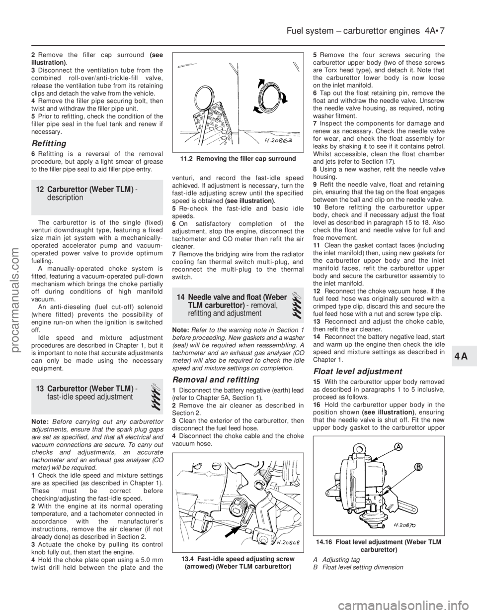
2Remove the filler cap surround (see
illustration) .
3 Disconnect the ventilation tube from the
combined roll-over/anti-trickle-fill valve,
release the ventilation tube from its retaining
clips and detach the valve from the vehicle.
4 Remove the filler pipe securing bolt, then
twist and withdraw the filler pipe unit.
5 Prior to refitting, check the condition of the
filler pipe seal in the fuel tank and renew if
necessary.
Refitting
6 Refitting is a reversal of the removal
procedure, but apply a light smear of grease
to the filler pipe seal to aid filler pipe entry.
12 Carburettor (Weber TLM) -
description
The carburettor is of the single (fixed)
venturi downdraught type, featuring a fixed
size main jet system with a mechanically-
operated accelerator pump and vacuum-
operated power valve to provide optimum
fuelling. A manually-operated choke system is
fitted, featuring a vacuum-operated pull-down
mechanism which brings the choke partially
off during conditions of high manifold
vacuum. An anti-dieseling (fuel cut-off) solenoid
(where fitted) prevents the possibility of
engine run-on when the ignition is switched
off. Idle speed and mixture adjustment
procedures are described in Chapter 1, but it
is important to note that accurate adjustments
can only be made using the necessary
equipment.
13 Carburettor (Weber TLM) -
fast-idle speed adjustment
4
Note: Before carrying out any carburettor
adjustments, ensure that the spark plug gaps
are set as specified, and that all electrical and
vacuum connections are secure. To carry out
checks and adjustments, an accurate
tachometer and an exhaust gas analyser (CO
meter) will be required.
1 Check the idle speed and mixture settings
are as specified (as described in Chapter 1).
These must be correct before
checking/adjusting the fast-idle speed.
2 With the engine at its normal operating
temperature, and a tachometer connected in
accordance with the manufacturer’s
instructions, remove the air cleaner (if not
already done) as described in Section 2.
3 Actuate the choke by pulling its control
knob fully out, then start the engine.
4 Hold the choke plate open using a 5.0 mm
twist drill held between the plate and the venturi, and record the fast-idle speed
achieved. If adjustment is necessary, turn the
fast-idle adjusting screw until the specified
speed is obtained
(see illustration).
5 Re-check the fast-idle and basic idle
speeds.
6 On satisfactory completion of the
adjustment, stop the engine, disconnect the
tachometer and CO meter then refit the air
cleaner.
7 Remove the bridging wire from the radiator
cooling fan thermal switch multi-plug, and
reconnect the multi-plug to the thermal
switch.
14 Needle valve and float (Weber
TLM carburettor) - removal,
refitting and adjustment
4
Note: Refer to the warning note in Section 1
before proceeding. New gaskets and a washer
(seal) will be required when reassembling. A
tachometer and an exhaust gas analyser (CO
meter) will also be required to check the idle
speed and mixture settings on completion.
Removal and refitting
1 Disconnect the battery negative (earth) lead
(refer to Chapter 5A, Section 1).
2 Remove the air cleaner as described in
Section 2.
3 Clean the exterior of the carburettor, then
disconnect the fuel feed hose.
4 Disconnect the choke cable and the choke
vacuum hose. 5
Remove the four screws securing the
carburettor upper body (two of these screws
are Torx head type), and detach it. Note that
the carburettor lower body is now loose
on the inlet manifold.
6 Tap out the float retaining pin, remove the
float and withdraw the needle valve. Unscrew
the needle valve housing, as required, noting
washer fitment.
7 Inspect the components for damage and
renew as necessary. Check the needle valve
for wear, and check the float assembly for
leaks by shaking it to see if it contains petrol.
Whilst accessible, clean the float chamber
and jets (refer to Section 17).
8 Using a new washer, refit the needle valve
housing.
9 Refit the needle valve, float and retaining
pin, ensuring that the tag on the float engages
between the ball and clip on the needle valve.
10 Before refitting the carburettor upper
body, check and if necessary adjust the float
level as described in paragraph 15 to 18. Also
check the float and needle valve for full and
free movement.
11 Clean the gasket contact faces (including
the inlet manifold) then, using new gaskets for
the carburettor upper body and the inlet
manifold faces, refit the carburettor upper
body and secure the carburettor assembly to
the inlet manifold.
12 Reconnect the choke vacuum hose. If the
fuel feed hose was originally secured with a
crimped type clip, discard this and secure the
fuel feed hose with a nut and screw type clip.
13 Reconnect and adjust the choke cable,
then refit the air cleaner.
14 Reconnect the battery negative lead, start
and warm up the engine then check the idle
speed and mixture settings as described in
Chapter 1.
Float level adjustment
15 With the carburettor upper body removed
as described in paragraphs 1 to 5 inclusive,
proceed as follows.
16 Hold the carburettor upper body in the
position shown (see illustration) , ensuring
that the needle valve is shut off. Fit the new
upper body gasket to the carburettor upper
Fuel system – carburettor engines 4A•7
13.4 Fast-idle speed adjusting screw (arrowed) (Weber TLM carburettor)
11.2 Removing the filler cap surround
14.16 Float level adjustment (Weber TLM carburettor)
A Adjusting tag
B Float level setting dimension
4A
1595Ford Fiesta Remakeprocarmanuals.com
http://vnx.su
Page 121 of 296
tachometer and an exhaust gas analyser (CO
meter) will be required.
1Check that the idle speed and mixture
settings are as specified (as described in
Chapter 1). These must be correct before
checking/adjusting the fast-idle speed.
2 Switch the engine off, then remove the air
cleaner as described in Section 2.
3 With the engine at its normal operating
temperature and a tachometer connected in
accordance with its manufacturer’s
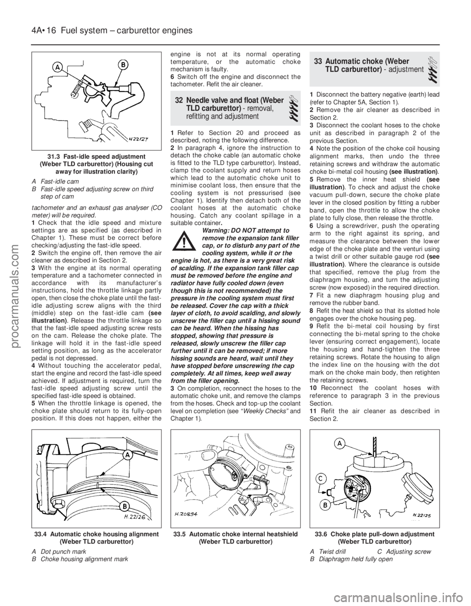
instructions, hold the throttle linkage partly
open, then close the choke plate until the fast-
idle adjusting screw aligns with the third
(middle) step on the fast-idle cam (see
illustration) . Release the throttle linkage so
that the fast-idle speed adjusting screw rests
on the cam. Release the choke plate. The
linkage will hold it in the fast-idle speed
setting position, as long as the accelerator
pedal is not depressed.
4 Without touching the accelerator pedal,
start the engine and record the fast-idle speed
achieved. If adjustment is required, turn the
fast-idle speed adjusting screw until the
specified fast-idle speed is obtained.
5 When the throttle linkage is opened, the
choke plate should return to its fully-open
position. If this does not happen, either the engine is not at its normal operating
temperature, or the automatic choke
mechanism is faulty.
6
Switch off the engine and disconnect the
tachometer. Refit the air cleaner.
32 Needle valve and float (Weber
TLD carburettor) - removal,
refitting and adjustment
4
1 Refer to Section 20 and proceed as
described, noting the following difference.
2 In paragraph 4, ignore the instruction to
detach the choke cable (an automatic choke
is fitted to the TLD type carburettor). Instead,
clamp the coolant supply and return hoses
which lead to the automatic choke unit to
minimise coolant loss, then ensure that the
cooling system is not pressurised (see
Chapter 1). Identify then detach both of the
coolant hoses at the automatic choke
housing. Catch any coolant spillage in a
suitable container .
Warning: DO NOT attempt to
remove the expansion tank filler
cap, or to disturb any part of the
cooling system, while it or the
engine is hot, as there is a very great risk
of scalding. If the expansion tank filler cap
must be removed before the engine and
radiator have fully cooled down (even
though this is not recommended) the
pressure in the cooling system must first
be released. Cover the cap with a thick
layer of cloth, to avoid scalding, and slowly
unscrew the filler cap until a hissing sound
can be heard. When the hissing has
stopped, showing that pressure is
released, slowly unscrew the filler cap
further until it can be removed; if more
hissing sounds are heard, wait until they
have stopped before unscrewing the cap
completely. At all times, keep well away
from the filler opening.
3 On completion, reconnect the hoses to the
automatic choke unit, and remove the clamps
from the hoses. Check and top-up the coolant
level on completion (see “Weekly Checks”and
Chapter 1).
33 Automatic choke (Weber TLD carburettor) - adjustment
3
1Disconnect the battery negative (earth) lead
(refer to Chapter 5A, Section 1).
2 Remove the air cleaner as described in
Section 2.
3 Disconnect the coolant hoses to the choke
unit as described in paragraph 2 of the
previous Section.
4 Note the position of the choke coil housing
alignment marks, then undo the three
retaining screws and withdraw the automatic
choke bi-metal coil housing (see illustration).
5 Remove the inner heat shield (see
illustration) . To check and adjust the choke
vacuum pull-down, secure the choke plate
lever in the closed position by fitting a rubber
band, open the throttle to allow the choke
plate to fully close, then release the throttle.
6 Using a screwdriver, push the operating
arm to the right against its spring, and
measure the clearance between the lower
edge of the choke plate and the venturi using
a twist drill or other suitable gauge rod (see
illustration) . Where the clearance is outside
that specified, remove the plug from the
diaphragm housing, and turn the adjusting
screw (now exposed) in the required direction.
7 Fit a new diaphragm housing plug and
remove the rubber band.
8 Refit the heat shield so that its slotted hole
engages over the choke housing peg.
9 Refit the bi-metal coil housing by first
connecting the bi-metal spring to the choke
lever (ensuring correct engagement), locate
the housing and hand-tighten the three
retaining screws. Rotate the housing to align
the index line on the housing with the dot
mark on the choke main body, then retighten
the retaining screws.
10 Reconnect the coolant hoses with
reference to paragraph 3 in the previous
Section.
11 Refit the air cleaner as described in
Section 2.
4A•16 Fuel system – carburettor engines
33.6 Choke plate pull-down adjustment (Weber TLD carburettor)
A Twist drill C Adjusting screw
B Diaphragm held fully open33.5 Automatic choke internal heatshield (Weber TLD carburettor)33.4 Automatic choke housing alignment(Weber TLD carburettor)
A Dot punch mark
B Choke housing alignment mark
1595Ford Fiesta Remake
31.3 Fast-idle speed adjustment
(Weber TLD carburettor) (Housing cut away for illustration clarity)
A Fast-idle cam
B Fast-idle speed adjusting screw on third step of cam
procarmanuals.com
http://vnx.su
Page 122 of 296
34 Automatic choke (WeberTLD carburettor) - removal,
inspection and refitting
4
Note: Refer to the warning note in Section 1
before proceeding. A new carburettor upper
body gasket will be required when
reassembling. On completion, a tachometer
will be required to check the fast-idle speed
adjustment.
Removal
1 Disconnect the battery negative (earth) lead
(refer to Chapter 5A, Section 1).
2 Remove the air cleaner as described in
Section 2.
3 To prevent excess coolant loss, clamp the
coolant supply and return hoses to the
automatic choke unit, and ensure that the
cooling system is not pressurised (see
Chapter 1). Identify then detach both of the
coolant hoses at the automatic choke
housing. Catch any coolant spillage in a
suitable container.
Warning: DO NOT attempt to
remove the expansion tank filler
cap, or to disturb any part of the
cooling system, while it or the
engine is hot, as there is a very great risk
of scalding. If the expansion tank filler cap
must be removed before the engine and
radiator have fully cooled down (even
though this is not recommended) the
pressure in the cooling system must first
be released. Cover the cap with a thick
layer of cloth, to avoid scalding, and slowly
unscrew the filler cap until a hissing sound
can be heard. When the hissing has
stopped, showing that pressure is
released, slowly unscrew the filler cap
further until it can be removed; if more
hissing sounds are heard, wait until they
have stopped before unscrewing the cap
completely. At all times, keep well away
from the filler opening.
4 Detach the fuel pipe and the anti-dieseling
solenoid wiring connector. Any crimped type
hose clips must be replaced with a screw
clamp type clips during reassembly.
5 Unscrew and remove the retaining screws (two conventional, and four Torx type), then lift
the carburettor upper body clear and remove it.
6
Note the position of the choke housing
alignment marks, then undo the three retaining
screws and remove the choke bi-metal coil
unit. Remove the internal heat shield.
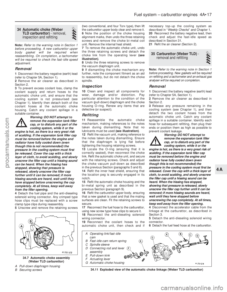
7 To remove the automatic choke unit, undo
the three retaining screws and detach the
choke link from the operating lever (see
illustration) .
8 Undo the three retaining screws to remove
the vacuum diaphragm unit.
9 If dismantling the choke mechanism any
further, note the component fitment as an aid
to reassembly, but do not detach the choke
spindle.
Inspection
10 Clean and inspect all components for
wear, damage and/or distortion. Pay
particular attention to the condition of the
vacuum (pull-down) diaphragm and the choke
housing O-ring. Renew any items that are
defective (or suspect).
Refitting
11 Reassemble the automatic choke
mechanism, making references to the notes
taken during dismantling. Note that no
lubricants must be used (see illustration).
12 Refit the vacuum unit, making reference to
the notes taken during dismantling. Ensure
that the diaphragm is lying flat before
tightening the housing retaining screws.
13 Locate the O-ring (ensuring that it is
correctly seated), then reconnect the choke
link. Refit the automatic choke unit, and secure
with the retaining screws. Check and adjust
the choke vacuum pull-down as described
in the previous Section (paragraphs 5 and 6).
14 Refit the inner heat shield, ensuring that
the location peg is securely engaged in its
notch.
15 Refit the automatic choke housing and the
bi-metal spring unit as described in the
previous Section (paragraph 9).
16 Refit the carburettor upper body, ensuring
that a new gasket is used and that the mating
surfaces are clean. Fit the retaining screws to
secure.
17 Reconnect the fuel hose to the carburettor,
using new screw type hose clips to secure it.
18 Reconnect the anti-dieseling solenoid
wiring connector.
19 Reconnect the coolant hoses to the
automatic choke unit, then check and if necessary top-up the cooling system as
described in “
Weekly Checks ” and Chapter 1.
20 Reconnect the battery negative lead, then
check and adjust the fast-idle speed as
described in Section 31.
21 Refit the air cleaner (Section 2).
35 Carburettor (Weber TLD) -
removal and refitting
4
Note: Refer to the warning note in Section 1
before proceeding. New gaskets will be required
on refitting and a tachometer and an exhaust gas
analyser will be required on completion.
Removal
1 Disconnect the battery negative (earth) lead
(refer to Chapter 5A, Section 1).
2 Remove the air cleaner as described in
Section 2.
3 Release any pressure remaining in the
cooling system (see Chapter 1), and then
detach the two coolant hoses from the
automatic choke unit. Catch any coolant
spillage in a suitable container. Identify each
hose for subsequent refitting, then plug their
ends or position them as high as possible to
prevent coolant leakage. Warning: DO NOT attempt to
remove the expansion tank filler
cap, or to disturb any part of the
cooling system, while it or the
engine is hot, as there is a very great risk of
scalding. If the expansion tank filler cap
must be removed before the engine and
radiator have fully cooled down (even
though this is not recommended) the
pressure in the cooling system must first be
released. Cover the cap with a thick layer of
cloth, to avoid scalding, and slowly unscrew
the filler cap until a hissing sound can be
heard. When the hissing has stopped,
showing that pressure is released, slowly
unscrew the filler cap further until it can be
removed; if more hissing sounds are heard,
wait until they have stopped before
unscrewing the cap completely. At all times,
keep well away from the filler opening.
4 Disconnect the accelerator cable from the
linkage at the carburettor, as described in
Section 3.
5 Detach the anti-dieseling solenoid wiring
connector.
6 Detach the fuel feed hose at the carburettor.
Fuel system – carburettor engines 4A•17
34.11 Exploded view of the automatic choke linkage (Weber TLD carburet\
tor)
34.7 Automatic choke assembly
(Weber TLD carburettor)
A Pull-down diaphragm housing
B Securing screws
4A
1595Ford Fiesta Remake
A Operating link/fast-idle cam
B Fast-idle cam return spring
C Spindle sleeve
D Connecting rod and lever assembly
E Pull-down kink
F Actuating lever
G Automatic choke housing
procarmanuals.com
http://vnx.su
Page 125 of 296
1 General information andprecautions
General information
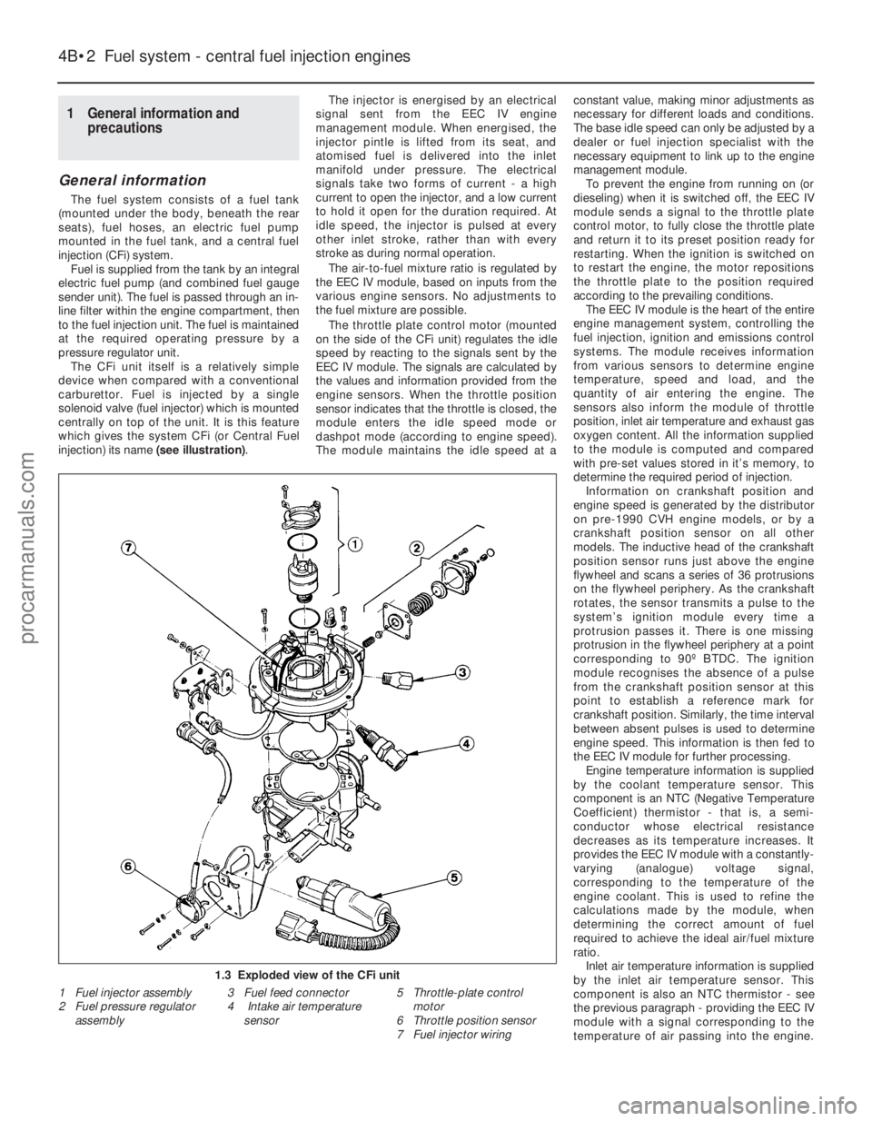
The fuel system consists of a fuel tank
(mounted under the body, beneath the rear
seats), fuel hoses, an electric fuel pump
mounted in the fuel tank, and a central fuel
injection (CFi) system. Fuel is supplied from the tank by an integral
electric fuel pump (and combined fuel gauge
sender unit). The fuel is passed through an in-
line filter within the engine compartment, then
to the fuel injection unit. The fuel is maintained
at the required operating pressure by a
pressure regulator unit. The CFi unit itself is a relatively simple
device when compared with a conventional
carburettor. Fuel is injected by a single
solenoid valve (fuel injector) which is mounted
centrally on top of the unit. It is this feature
which gives the system CFi (or Central Fuel
injection) its name (see illustration).The injector is energised by an electrical
signal sent from the EEC IV engine
management module. When energised, the
injector pintle is lifted from its seat, and
atomised fuel is delivered into the inlet
manifold under pressure. The electrical
signals take two forms of current - a high
current to open the injector, and a low current
to hold it open for the duration required. At
idle speed, the injector is pulsed at every
other inlet stroke, rather than with every
stroke as during normal operation.
The air-to-fuel mixture ratio is regulated by
the EEC IV module, based on inputs from the
various engine sensors. No adjustments to
the fuel mixture are possible.
The throttle plate control motor (mounted
on the side of the CFi unit) regulates the idle
speed by reacting to the signals sent by the
EEC IV module. The signals are calculated by
the values and information provided from the
engine sensors. When the throttle position
sensor indicates that the throttle is closed, the
module enters the idle speed mode or
dashpot mode (according to engine speed).
The module maintains the idle speed at a constant value, making minor adjustments as
necessary for different loads and conditions.
The base idle speed can only be adjusted by a
dealer or fuel injection specialist with the
necessary equipment to link up to the engine
management module.
To prevent the engine from running on (or
dieseling) when it is switched off, the EEC IV
module sends a signal to the throttle plate
control motor, to fully close the throttle plate
and return it to its preset position ready for
restarting. When the ignition is switched on
to restart the engine, the motor repositions
the throttle plate to the position required
according to the prevailing conditions. The EEC IV module is the heart of the entire
engine management system, controlling the
fuel injection, ignition and emissions control
systems. The module receives information
from various sensors to determine engine
temperature, speed and load, and the
quantity of air entering the engine. The
sensors also inform the module of throttle
position, inlet air temperature and exhaust gas
oxygen content. All the information supplied
to the module is computed and compared
with pre-set values stored in it’s memory, to
determine the required period of injection. Information on crankshaft position and
engine speed is generated by the distributor
on pre-1990 CVH engine models, or by a
crankshaft position sensor on all other
models. The inductive head of the crankshaft
position sensor runs just above the engine
flywheel and scans a series of 36 protrusions
on the flywheel periphery. As the crankshaft
rotates, the sensor transmits a pulse to the
system’s ignition module every time a
protrusion passes it. There is one missing
protrusion in the flywheel periphery at a point
corresponding to 90º BTDC. The ignition
module recognises the absence of a pulse
from the crankshaft position sensor at this
point to establish a reference mark for
crankshaft position. Similarly, the time interval
between absent pulses is used to determine
engine speed. This information is then fed to
the EEC IV module for further processing. Engine temperature information is supplied
by the coolant temperature sensor. This
component is an NTC (Negative Temperature
Coefficient) thermistor - that is, a semi-
conductor whose electrical resistance
decreases as its temperature increases. It
provides the EEC IV module with a constantly-
varying (analogue) voltage signal,
corresponding to the temperature of the
engine coolant. This is used to refine the
calculations made by the module, when
determining the correct amount of fuel
required to achieve the ideal air/fuel mixture
ratio. Inlet air temperature information is supplied
by the inlet air temperature sensor. This
component is also an NTC thermistor - see
the previous paragraph - providing the EEC IV
module with a signal corresponding to the
temperature of air passing into the engine.
4B•2 Fuel system - central fuel injection engines
1.3 Exploded view of the CFi unit
1 Fuel injector assembly
2 Fuel pressure regulator
assembly 3 Fuel feed connector
4 Intake air temperature
sensor 5 Throttle-plate control
motor
6 Throttle position sensor
7 Fuel injector wiring
1595Ford Fiesta Remakeprocarmanuals.com
http://vnx.su