1989 FORD FIESTA jack points
[x] Cancel search: jack pointsPage 22 of 296
23 Coolant renewal
1
Note: If the antifreeze used is Ford’s own, the
coolant need not be renewed for the life of the
vehicle. If the vehicle’s history is unknown, if
antifreeze of lesser quality is known to be in
the system, or simply if you prefer to follow
conventional servicing intervals, the coolant
should be changed periodically (typically,
every 3 years) as described here. Refer also to
“Antifreeze - notes on renewal” in this
Section.
Warning: Do not allow
antifreeze to come in contact
with your skin or painted
surfaces of the vehicle. Flush
contaminated areas immediately with
plenty of water. Don’t store new coolant,
or leave old coolant lying around, where
it’s accessible to children or pets - they’re
attracted by its sweet smell. Ingestion of
even a small amount of coolant can be
fatal! Wipe up garage-floor and drip-pan
spills immediately. Keep antifreeze
containers covered, and repair cooling
system leaks as soon as they’re noticed.
Warning: Never remove the expansion
tank filler cap when the engine is running,
or has just been switched off, as the
cooling system will be hot, and the
consequent escaping steam and scalding
coolant could cause serious injury.
Coolant draining
Warning: Wait until the engine is
cold before starting this
procedure.
1 To drain the system, first remove the
expansion tank filler cap (see “Weekly
Checks” ).
2 If additional working clearance is required,
raise the front of the vehicle and support it securely on axle stands (see
“Jacking and
Vehicle Support” ).
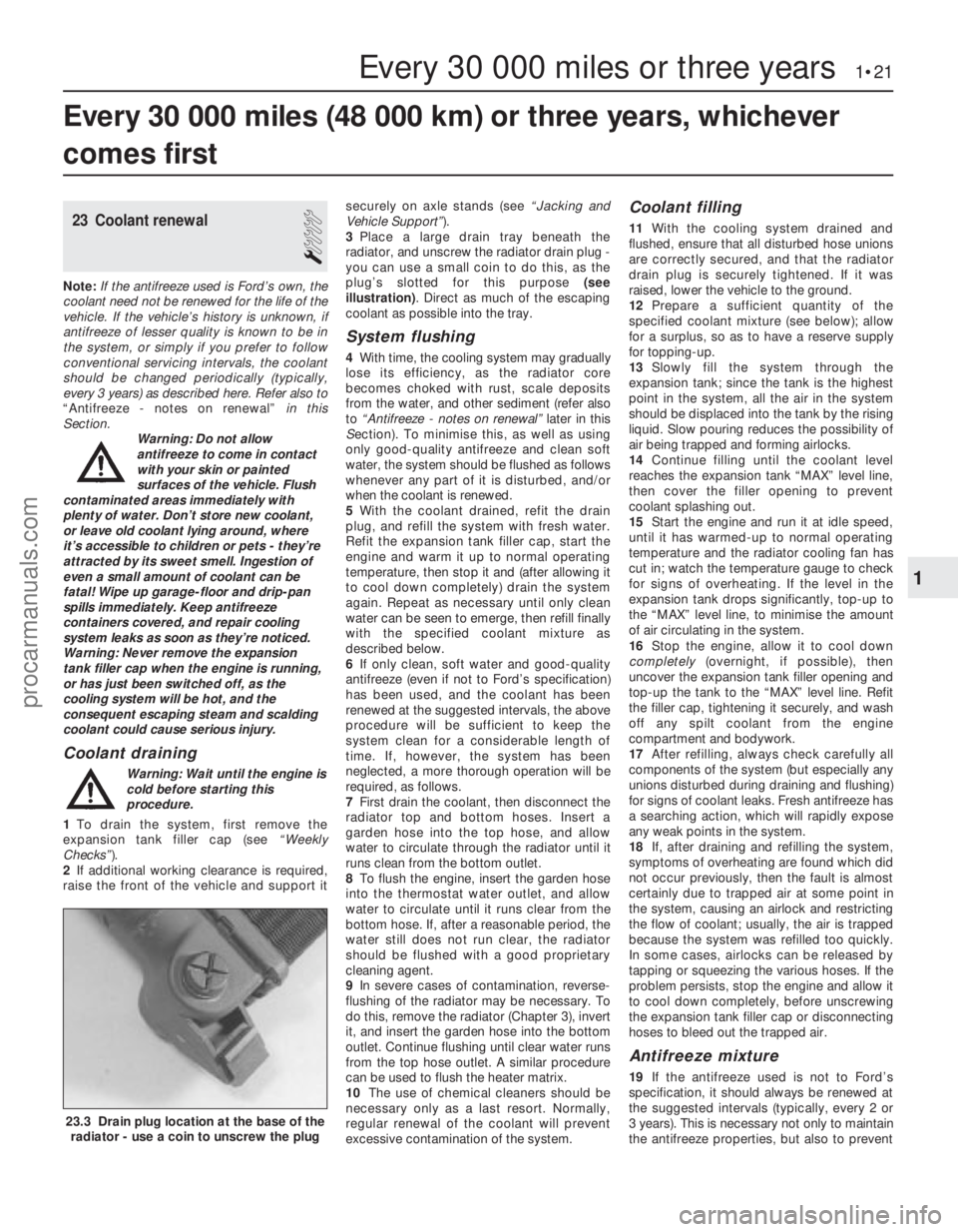
3 Place a large drain tray beneath the
radiator, and unscrew the radiator drain plug -
you can use a small coin to do this, as the
plug’s slotted for this purpose (see
illustration) . Direct as much of the escaping
coolant as possible into the tray.
System flushing
4 With time, the cooling system may gradually
lose its efficiency, as the radiator core
becomes choked with rust, scale deposits
from the water, and other sediment (refer also
to “Antifreeze - notes on renewal” later in this
S ection). To minimise this, as well as using
only good-quality antifreeze and clean soft
water, the system should be flushed as follows
whenever any part of it is disturbed, and/or
when the coolant is renewed.
5 With the coolant drained, refit the drain
plug, and refill the system with fresh water.
Refit the expansion tank filler cap, start the
engine and warm it up to normal operating
temperature, then stop it and (after allowing it
to cool down completely) drain the system
again. Repeat as necessary until only clean
water can be seen to emerge, then refill finally
with the specified coolant mixture as
described below.
6 If only clean, soft water and good-quality
antifreeze (even if not to Ford’s specification)
has been used, and the coolant has been
renewed at the suggested intervals, the above
procedure will be sufficient to keep the
system clean for a considerable length of
time. If, however, the system has been
neglected, a more thorough operation will be
required, as follows.
7 First drain the coolant, then disconnect the
radiator top and bottom hoses. Insert a
garden hose into the top hose, and allow
water to circulate through the radiator until it
runs clean from the bottom outlet.
8 To flush the engine, insert the garden hose
into the thermostat water outlet, and allow
water to circulate until it runs clear from the
bottom hose. If, after a reasonable period, the
water still does not run clear, the radiator
should be flushed with a good proprietary
cleaning agent.
9 In severe cases of contamination, reverse-
flushing of the radiator may be necessary. To
do this, remove the radiator (Chapter 3), invert
it, and insert the garden hose into the bottom
outlet. Continue flushing until clear water runs
from the top hose outlet. A similar procedure
can be used to flush the heater matrix.
10 The use of chemical cleaners should be
necessary only as a last resort. Normally,
regular renewal of the coolant will prevent
excessive contamination of the system.
Coolant filling
11 With the cooling system drained and
flushed, ensure that all disturbed hose unions
are correctly secured, and that the radiator
drain plug is securely tightened. If it was
raised, lower the vehicle to the ground.
12 Prepare a sufficient quantity of the
specified coolant mixture (see below); allow
for a surplus, so as to have a reserve supply
for topping-up.
13 Slowly fill the system through the
expansion tank; since the tank is the highest
point in the system, all the air in the system
should be displaced into the tank by the rising
liquid. Slow pouring reduces the possibility of
air being trapped and forming airlocks.
14 Continue filling until the coolant level
reaches the expansion tank “MAX” level line,
then cover the filler opening to prevent
coolant splashing out.
15 Start the engine and run it at idle speed,
until it has warmed-up to normal operating
temperature and the radiator cooling fan has
cut in; watch the temperature gauge to check
for signs of overheating. If the level in the
expansion tank drops significantly, top-up to
the “MAX” level line, to minimise the amount
of air circulating in the system.
16 Stop the engine, allow it to cool down
completely (overnight, if possible), then
uncover the expansion tank filler opening and
top-up the tank to the “MAX” level line. Refit
the filler cap, tightening it securely, and wash
off any spilt coolant from the engine
compartment and bodywork.
17 After refilling, always check carefully all
components of the system (but especially any
unions disturbed during draining and flushing)
for signs of coolant leaks. Fresh antifreeze has
a searching action, which will rapidly expose
any weak points in the system.
18 If, after draining and refilling the system,
symptoms of overheating are found which did
not occur previously, then the fault is almost
certainly due to trapped air at some point in
the system, causing an airlock and restricting
the flow of coolant; usually, the air is trapped
because the system was refilled too quickly.
In some cases, airlocks can be released by
tapping or squeezing the various hoses. If the
problem persists, stop the engine and allow it
to cool down completely, before unscrewing
the expansion tank filler cap or disconnecting
hoses to bleed out the trapped air.
Antifreeze mixture
19 If the antifreeze used is not to Ford’s
specification, it should always be renewed at
the suggested intervals (typically, every 2 or
3 years). This is necessary not only to maintain
the antifreeze properties, but also to prevent
Every 30 000 miles (48 000 km) or three years, whichever
comes first
Every 30 000 miles or three years 1•21
23.3 Drain plug location at the base of the radiator - use a coin to unscrew the plug
1
1595Ford Fiesta Remakeprocarmanuals.com
http://vnx.su
Page 26 of 296
the specified type of fluid. It is essential that
no dirt is introduced into the transmission
during this operation.
7Depending on the extent to which the fluid
was allowed to drain, it is possible that the
amount of fluid required when filling the
transmission may be more than the specified
amount (see “Lubricants, fluids and tyre
pressures” ). However, due to fluid remaining in
the system, it is more likely that less than the
specified amount will be required. Add about
half the specified amount, then run the engine
up to its normal operating temperature and
check the level on the dipstick. When the level
approaches the maximum mark, proceed as
detailed in Section 20 to check the level and
complete the final topping-up as described.
27 Handbrake adjustment
3
1 Chock the front wheels then jack up the
rear of the car and support it on axle stands
(see “Jacking and Vehicle Support” ). Fully
release the handbrake.
2 Check that the handbrake cables are
correctly routed and secured by the retaining
clips at the appropriate points under the vehicle.
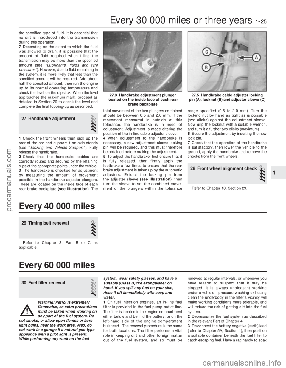
3 The handbrake is checked for adjustment
by measuring the amount of movement
possible in the handbrake adjuster plungers.
These are located on the inside face of each
rear brake backplate (see illustration) . Thetotal movement of the two plungers combined
should be between 0.5 and 2.0 mm. If the
movement measured is outside of this
tolerance, the handbrake is in need of
adjustment. Adjustment is made altering the
position of the in-line cable adjuster sleeve.
4
When adjustment to the handbrake is
necessary, a new adjustment sleeve locking
pin will be required, and this must therefore
be obtained before making the adjustment.
5 To adjust the handbrake, first ensure that it
is fully released, then firmly apply the
footbrake a few times to ensure that the rear
brake adjustment is taken up by the automatic
adjusters. Extract the locking pin from
the adjuster sleeve (see illustration), then
turn the sleeve to set the combined move-
ment of the plungers within the tolerance range specified (0.5 to 2.0 mm). Turn the
locking nut by hand as tight as is possible
(two clicks) against the adjustment sleeve.
Now grip the locknut with a suitable wrench,
and turn it a further two clicks (maximum).
6
Secure the adjustment by inserting the new
lock pin.
7 Check that the operation of the handbrake
is satisfactory, then lower the vehicle to the
ground, apply the handbrake and remove the
chocks from the front wheels.
28 Front wheel alignment check
4
Refer to Chapter 10, Section 29.
Every 30 000 miles or three years1•25
27.5 Handbrake cable adjuster locking
pin (A), locknut (B) and adjuster sleeve (C)27.3 Handbrake adjustment plunger
located on the inside face of each rear brake backplate
1
1595Ford Fiesta Remake
Every 40 000 miles
29 Timing belt renewal
4
Refer to Chapter 2, Part B or C as
applicable.
Every 60 000 miles
30 Fuel filter renewal
1
Warning: Petrol is extremely
flammable, so extra precautions
must be taken when working on
any part of the fuel system. Do
not smoke, or allow open flames or bare
light bulbs, near the work area. Also, do
not work in a garage if a natural gas-type appliance with a pilot light is present.
While performing any work on the fuel system, wear safety glasses, and have a
suitable (Class B) fire extinguisher on
hand. If you spill any fuel on your skin,
rinse it off immediately with soap and
water.
1
On fuel injection engines, an in-line fuel
filter is provided in the fuel pump outlet line.
The filter is located in the engine compartment
either below and behind the battery, or on the
left-hand side of the engine compartment
bulkhead. The renewal procedure is the same
for both locations. The filter performs a vital
role in keeping dirt and other foreign matter
out of the fuel system, and so must be renewed at regular intervals, or whenever you
have reason to suspect that it may be
clogged. It is always unpleasant working
under a vehicle - pressure-washing or hosing
clean the underbody in the filter’s vicinity will
make working conditions more tolerable, and
will reduce the risk of getting dirt into the fuel
system.
2
Depressurise the fuel system as described
in the relevant Part of Chapter 4.
3 Disconnect the battery negative (earth) lead
(refer to Chapter 5A, Section 1), then position
a suitable container beneath the fuel filter to
catch escaping fuel. Have a rag handy to soak
procarmanuals.com
http://vnx.su
Page 69 of 296
4Check the mountings to see if the rubber is
cracked, hardened or separated from the
metal components. Sometimes, the rubber
will split right down the centre.
5 Check for relative movement between each
mounting’s brackets and the engine/
transmission or body (use a large screwdriver
or lever to attempt to move the mountings). If
movement is noted, lower the engine and
check-tighten the mounting fasteners.
Renewal
6 The engine mountings can be removed if
the weight of the engine/transmission is
supported by one of the following alternative
methods.
7 Either support the weight of the assembly
from underneath using a jack and a suitable
piece of wood between the jack saddle and
the sump or transmission (to prevent
damage), or from above by attaching a hoist
to the engine. A third method is to use a
suitable support bar with end pieces which
will engage in the water channel each side of
the bonnet lid aperture. Using an adjustable
hook and chain connected to the engine, the
weight of the engine and transmission can
then be taken from the mountings.
Engine front right-hand mounting
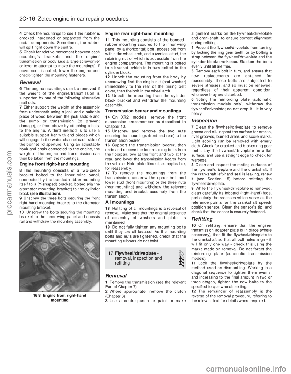
8 This mounting consists of a two-piece
bracket bolted to the inner wing panel,
connected by the bonded-rubber mounting
itself to a (Y-shaped) bracket, bolted (via the
alternator mounting bracket) to the cylinder
block (see illustration) .
9 Unscrew the three bolts securing the front
right-hand mounting bracket to the alternator
mounting bracket.
10 Unscrew the bolts securing the mounting
bracket to the inner wing panel and chassis
rail and withdraw the mounting assembly.
Engine rear right-hand mounting
11 This mounting consists of the bonded-
rubber mounting secured to the inner wing
panel by a (horizontal) bolt, accessible from
within the wheel arch, and a (vertical) stud, the
retaining nut of which is accessible from the
engine compartment. The mounting is bolted
to a bracket, which is in turn bolted to the
cylinder block.
12 Unbolt the mounting from the body by
unscrewing first the single nut (and washer)
immediately to the rear of the timing belt
cover, then the bolt in the wheel arch.
13 Unbolt the mounting from the cylinder
block bracket and withdraw the mounting
assembly.
Transmission bearer and mountings
14 On XR2i models, remove the front
suspension crossmember as described in
Chapter 10.
15 Unscrew and remove the two nuts
securing the mountings (front and rear) to the
transmission bearer
16 Support the transmission bearer, then
undo and remove the four retaining bolts from
the floorpan, two at the front and two at the
rear, and lower the transmission bearer from
the vehicle. Note plate fitment, as applicable,
for reassembly.
17 To remove the mountings from the
transmission, unscrew the upper bolt and
lower stud (front mounting) or the three nuts
(rear mounting) and withdraw the relevant
mounting and bracket assembly from the
transmission.
All mountings
18 Refitting of all mountings is a reversal of
removal. Make sure that the original sequence
of assembly of washers and plates is
maintained.
19 Do not fully tighten any mounting bolts
until they are all located. As the mounting
bolts and nuts are tightened, check that the
mounting rubbers do not twist.
17 Flywheel/driveplate -
removal, inspection and
refitting
3
Removal
1 Remove the transmission (see the relevant
Part of Chapter 7).
2 Where appropriate, remove the clutch
(Chapter 6).
3 Use a centre-punch or paint to make alignment marks on the flywheel/driveplate
and crankshaft, to ensure correct alignment
during refitting.
4
Prevent the flywheel/driveplate from turning
by locking the ring gear teeth, or by bolting a
strap between the flywheel/driveplate and the
cylinder block/crankcase. Slacken the bolts
evenly until all are free.
5 Remove each bolt in turn, and ensure that
new replacements are obtained for
reassembly; these bolts are subjected to
severe stresses, and so must be renewed,
regardless of their apparent condition,
whenever they are disturbed.
6 Noting the reinforcing plate (automatic
transmission models only), withdraw the
flywheel/driveplate; do not drop it - it is very
heavy.
Inspection
7 Clean the flywheel/driveplate to remove
grease and oil. Inspect the surface for cracks,
rivet grooves, burned areas and score marks.
Light scoring can be removed with emery
cloth. Check for cracked and broken ring gear
teeth. Lay the flywheel/driveplate on a flat
surface, and use a straight edge to check for
warpage.
8 Clean and inspect the mating surfaces of
the flywheel/driveplate and the crankshaft. If
the crankshaft left-hand seal is leaking, renew
it (see Section 15) before refitting the
flywheel/driveplate.
9 While the flywheel/driveplate is removed,
clean carefully its inboard (right-hand) face,
particularly the recesses which serve as the
reference points for the crankshaft speed/
position sensor. Clean the sensor’s tip, and
check that the sensor is securely fastened.
Refitting
10 On refitting, ensure that the engine/
transmission adapter plate is in place (where
necessary), then fit the flywheel/driveplate to
the crankshaft so that all bolt holes align - it
will fit only one way - check this using the
marks made on removal. Do not forget the
reinforcing plate (automatic transmission
models).
11 Lock the flywheel/driveplate by the
method used on dismantling. Working in a
diagonal sequence to tighten them evenly,
and increasing to the final amount in two or
three stages, tighten the new bolts to the
specified torque wrench setting.
12 The remainder of reassembly is the
reverse of the removal procedure, referring to
the relevant text for details where required.
2C•16 Zetec engine in-car repair procedures
16.8 Engine front right-hand mounting
1595Ford Fiesta Remakeprocarmanuals.com
http://vnx.su
Page 77 of 296
transmission flange attachment bolts (see
illustration) .
19 Check that the appropriate underside
attachments are disconnected and out of the
way, then lower the vehicle to the ground.
20 Unbolt and remove the heat shield from
the exhaust manifold.
21 Attach a suitable hoist to the engine. It is
possible to fabricate lifting eyes to connect
the hoist to the engine, but make sure that
they are strong enough, and connect them to
the inlet and exhaust manifold at diagonally-
opposite ends of the engine.
22 With the hoist securely connected, take
the weight of the engine. Unscrew and
remove the right-hand engine mounting side
bolt from under the right-hand wheel arch.
Unscrew and remove the mounting retaining
nut and washer from the suspension strut cup
retaining plate, and the three bolts securing
the mounting unit to the cylinder block.
23 Locate a jack under the transmission, and
raise it to take the weight of the transmission.
24 Unscrew and remove the remaining
engine-to-transmission retaining bolts on the
upper flange.
25 Check around the engine to ensure that all
of the relevant fixings and attachments are
disconnected and out of the way for the
removal.
26 Enlist the aid of an assistant, then move
the engine sideways and away from the
transmission, whilst simultaneously raising
the transmission. When the engine is
separated from the transmission, carefully
guide it up and out of the engine
compartment. Do not allow the weight of the
engine to hang on the transmission input shaft
at any point during the removal (or refitting) of
the engine. When the engine sump is clear
of the vehicle, swing the power unit out of the
way, and lower it onto a trolley (if available).
Unless a mobile hoist is being used, it will be
necessary to move the vehicle rearwards and
out of the way in order to allow the engine to
be lowered for removal. In this instance,
ensure that the weight of the transmission is
well supported as the vehicle is moved.
27 While the engine is removed, check the
mountings; renew them if they are worn or
damaged. Similarly, check the condition of all
coolant and vacuum hoses and pipes (see Chapter 1); components that are normally
hidden can now be checked properly, and
should be renewed if there is any doubt at all
about their condition. Also, take the
opportunity to overhaul the clutch
components (see Chapter 6). It is regarded by
many as good working practice to renew the
clutch assembly as a matter of course,
whenever major engine overhaul work is
carried out. Check also the condition of all
components disturbed on removal, and renew
any that are damaged or worn.
Refitting
28
Refitting is in general, a reversal of the
removal procedure, but the following special
points should be noted.
29 Before coupling the engine to the
transmission, apply a thin smear of high-
melting-point grease onto the transmission
input shaft splines. If the clutch has been
removed, ensure that the clutch disc is
centralised, and disconnect the clutch cable
from the release lever on the transmission
casing.
30 Tighten all fixings to their recommended
torque wrench settings.
31 Check that the mating faces are clean,
and fit a new exhaust downpipe-to-manifold
gasket and self-locking nuts when
reconnecting this joint.
32 Ensure that all wiring connections are
correctly and securely made.
33 Remove the plugs from the fuel lines
before reconnecting them correctly and
securely.
34 Reconnect and adjust the accelerator and
choke cables as described in the relevant Part
of Chapter 4. The refitting details for the air
cleaner components are also given in that
Chapter.
35 Renew any coolant hoses (and/or
retaining clips) that are not in good condition.
36 Refer to Chapter 6 for details on
reconnecting the clutch cable.
37 When the engine is fully refitted, check
that the various hoses are connected, and
then top-up the engine oil and coolant levels
as described in Chapter 1 and “Weekly
Checks”.
38 When engine refitting is completed, refer to
Section 19 for the engine start-up procedures.
4 Engine/transmission -
removal and refitting (CVH and
PTE engines)
3
Warning: Petrol is extremely
flammable, so take extra
precautions when disconnecting
any part of the fuel system.
Don’t smoke, or allow naked flames or bare
light bulbs, in or near the work area, and
don’t work in a garage where a natural-gas
appliance (such as a clothes dryer or water
heater) is installed. If you spill petrol on
your skin, rinse it off immediately. Have a
fire extinguisher rated for petrol fires
handy, and know how to use it.
Note: Read through the entire Section, as well
as reading the advice in Section 2, before
beginning this procedure. The engine and
transmission are removed as a unit, lowered to
the ground and removed from underneath,
then separated outside the vehicle.
Removal
1 On all fuel injection engines, refer to
Chapter 4B, C or D as applicable and
depressurise the fuel system.
2 Disconnect the battery negative (earth) lead
(refer to Chapter 5A, Section 1).
3 Referring to Chapter 1 for details, drain the
coolant and the engine oil. Refit the drain plug
to the sump on completion.
4 Refer to Chapter 11 for details, and remove
the bonnet.
5 Remove the air cleaner assembly and air
inlet components as described in the relevant
Part of Chapter 4.
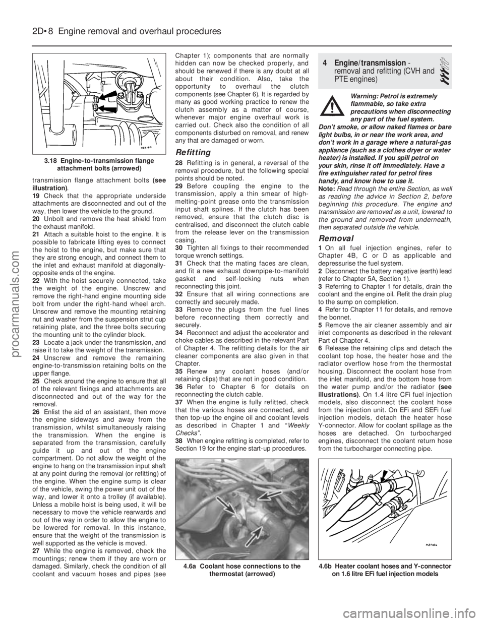
6 Release the retaining clips and detach the
coolant top hose, the heater hose and the
radiator overflow hose from the thermostat
housing. Disconnect the coolant hose from
the inlet manifold, and the bottom hose from
the water pump and/or the radiator (see
illustrations) . On 1.4 litre CFi fuel injection
models, also disconnect the coolant hose
from the injection unit. On EFi and SEFi fuel
injection models, detach the heater hose
Y-connector. Allow for coolant spillage as the
hoses are detached. On turbocharged
engines, disconnect the coolant return hose
from the turbocharger connecting pipe.
2D•8 Engine removal and overhaul procedures
4.6b Heater coolant hoses and Y-connector on 1.6 litre EFi fuel injection models4.6a Coolant hose connections to the thermostat (arrowed)
3.18 Engine-to-transmission flangeattachment bolts (arrowed)
1595Ford Fiesta Remakeprocarmanuals.com
http://vnx.su
Page 130 of 296
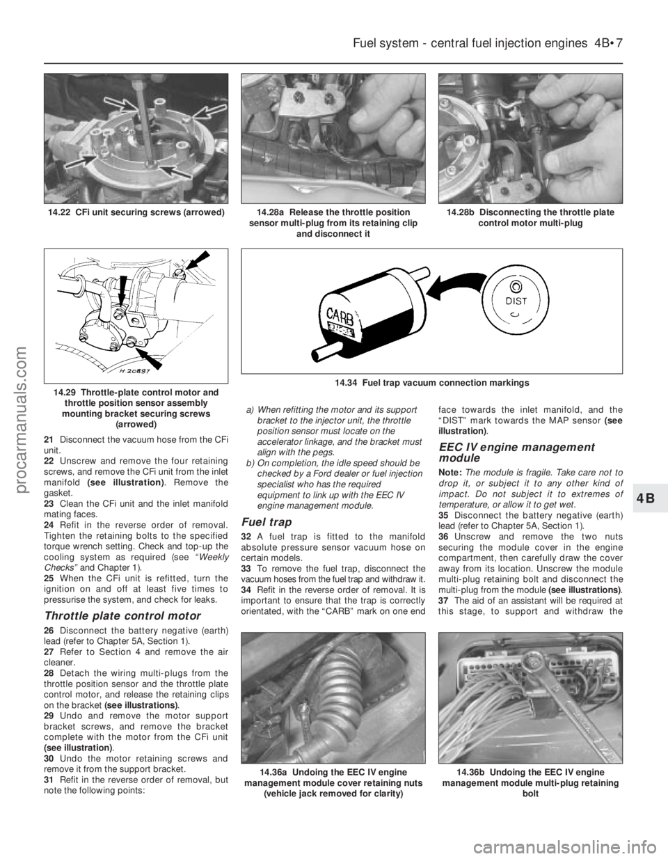
21Disconnect the vacuum hose from the CFi
unit.
22 Unscrew and remove the four retaining
screws, and remove the CFi unit from the inlet
manifold (see illustration) . Remove the
gasket.
23 Clean the CFi unit and the inlet manifold
mating faces.
24 Refit in the reverse order of removal.
Tighten the retaining bolts to the specified
torque wrench setting. Check and top-up the
cooling system as required (see “Weekly
Checks” and Chapter 1).
25 When the CFi unit is refitted, turn the
ignition on and off at least five times to
pressurise the system, and check for leaks.
Throttle plate control motor
26 Disconnect the battery negative (earth)
lead (refer to Chapter 5A, Section 1).
27 Refer to Section 4 and remove the air
cleaner.
28 Detach the wiring multi-plugs from the
throttle position sensor and the throttle plate
control motor, and release the retaining clips
on the bracket (see illustrations) .
29 Undo and remove the motor support
bracket screws, and remove the bracket
complete with the motor from the CFi unit
(see illustration) .
30 Undo the motor retaining screws and
remove it from the support bracket.
31 Refit in the reverse order of removal, but
note the following points: a) When refitting the motor and its support
bracket to the injector unit, the throttle
position sensor must locate on the
accelerator linkage, and the bracket must
align with the pegs.
b) On completion, the idle speed should be
checked by a Ford dealer or fuel injection
specialist who has the required
equipment to link up with the EEC IV
engine management module.
Fuel trap
32 A fuel trap is fitted to the manifold
absolute pressure sensor vacuum hose on
certain models.
33 To remove the fuel trap, disconnect the
vacuum hoses from the fuel trap and withdraw it.
34 Refit in the reverse order of removal. It is
important to ensure that the trap is correctly
orientated, with the “CARB” mark on one end face towards the inlet manifold, and the
“DIST” mark towards the MAP sensor
(see
illustration) .
EEC IV engine management
module
Note: The module is fragile. Take care not to
drop it, or subject it to any other kind of
impact. Do not subject it to extremes of
temperature, or allow it to get wet.
35 Disconnect the battery negative (earth)
lead (refer to Chapter 5A, Section 1).
36 Unscrew and remove the two nuts
securing the module cover in the engine
compartment, then carefully draw the cover
away from its location. Unscrew the module
multi-plug retaining bolt and disconnect the
multi-plug from the module (see illustrations).
37 The aid of an assistant will be required at
this stage, to support and withdraw the
Fuel system - central fuel injection engines 4B•7
14.28b Disconnecting the throttle plate control motor multi-plug14.28a Release the throttle position
sensor multi-plug from its retaining clip and disconnect it14.22 CFi unit securing screws (arrowed)
14.36b Undoing the EEC IV engine
management module multi-plug retaining
bolt
14.34 Fuel trap vacuum connection markings14.29 Throttle-plate control motor andthrottle position sensor assembly
mounting bracket securing screws (arrowed)
14.36a Undoing the EEC IV engine
management module cover retaining nuts
(vehicle jack removed for clarity)
4B
1595Ford Fiesta Remakeprocarmanuals.com
http://vnx.su
Page 140 of 296
Crankshaft position sensor
40Refer to Chapter 5B.
Coolant temperature sensor
41Refer to Chapter 3.
Inlet air temperature sensor
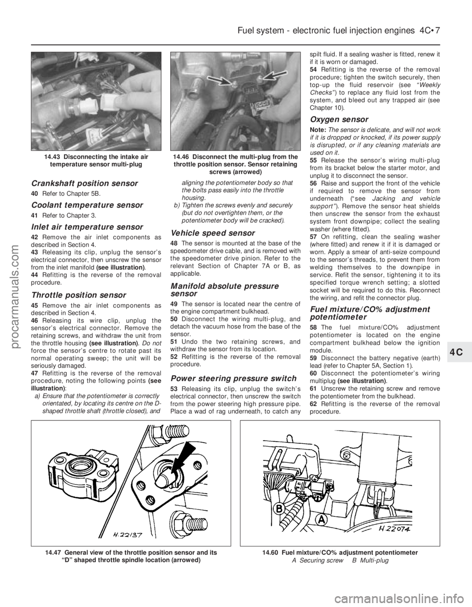
42Remove the air inlet components as
described in Section 4.
43 Releasing its clip, unplug the sensor’s
electrical connector, then unscrew the sensor
from the inlet manifold (see illustration).
44 Refitting is the reverse of the removal
procedure.
Throttle position sensor
45 Remove the air inlet components as
described in Section 4.
46 Releasing its wire clip, unplug the
sensor’s electrical connector. Remove the
retaining screws, and withdraw the unit from
the throttle housing (see illustration). Do not
force the sensor’s centre to rotate past its
normal operating sweep; the unit will be
seriously damaged.
47 Refitting is the reverse of the removal
procedure, noting the following points (see
illustration) :
a) Ensure that the potentiometer is correctly
orientated, by locating its centre on the D-
shaped throttle shaft (throttle closed), and aligning the potentiometer body so that
the bolts pass easily into the throttle
housing.
b) Tighten the screws evenly and securely
(but do not overtighten them, or the
potentiometer body will be cracked).
Vehicle speed sensor
48 The sensor is mounted at the base of the
speedometer drive cable, and is removed with
the speedometer drive pinion. Refer to the
relevant Section of Chapter 7A or B, as
applicable.
Manifold absolute pressure
sensor
49 The sensor is located near the centre of
the engine compartment bulkhead.
50 Disconnect the wiring multi-plug, and
detach the vacuum hose from the base of the
sensor.
51 Undo the two retaining screws, and
withdraw the sensor from its location.
52 Refitting is the reverse of the removal
procedure.
Power steering pressure switch
53 Releasing its clip, unplug the switch’s
electrical connector, then unscrew the switch
from the power steering high pressure pipe.
Place a wad of rag underneath, to catch any spilt fluid. If a sealing washer is fitted, renew it
if it is worn or damaged.
54
Refitting is the reverse of the removal
procedure; tighten the switch securely, then
top-up the fluid reservoir (see “Weekly
Checks” ) to replace any fluid lost from the
system, and bleed out any trapped air (see
Chapter 10).
Oxygen sensor
Note: The sensor is delicate, and will not work
if it is dropped or knocked, if its power supply
is disrupted, or if any cleaning materials are
used on it.
55 Release the sensor’s wiring multi-plug
from its bracket below the starter motor, and
unplug it to disconnect the sensor.
56 Raise and support the front of the vehicle
if required to remove the sensor from
underneath (“see Jacking and vehicle
support” ). Remove the sensor heat shields
then unscrew the sensor from the exhaust
system front downpipe; collect the sealing
washer (where fitted).
57 On refitting, clean the sealing washer
(where fitted) and renew it if it is damaged or
worn. Apply a smear of anti-seize compound
to the sensor’s threads, to prevent them from
welding themselves to the downpipe in
service. Refit the sensor, tightening it to its
specified torque wrench setting; a slotted
socket will be required to do this. Reconnect
the wiring, and refit the connector plug.
Fuel mixture/CO% adjustment
potentiometer
58 The fuel mixture/CO% adjustment
potentiometer is located on the engine
compartment bulkhead below the ignition
module.
59 Disconnect the battery negative (earth)
lead (refer to Chapter 5A, Section 1).
60 Disconnect the potentiometer’s wiring
multiplug (see illustration) .
61 Unscrew the retaining screw and remove
the potentiometer from the bulkhead.
62 Refitting is the reverse of the removal
procedure.
Fuel system - electronic fuel injection engines 4C•7
14.46 Disconnect the multi-plug from the throttle position sensor. Sensor retaining screws (arrowed)14.43 Disconnecting the intake airtemperature sensor multi-plug
14.60 Fuel mixture/CO% adjustment potentiometer
A Securing screw B Multi-plug14.47 General view of the throttle position sensor and its “D” shaped throttle spindle location (arrowed)
4C
1595Ford Fiesta Remakeprocarmanuals.com
http://vnx.su
Page 155 of 296
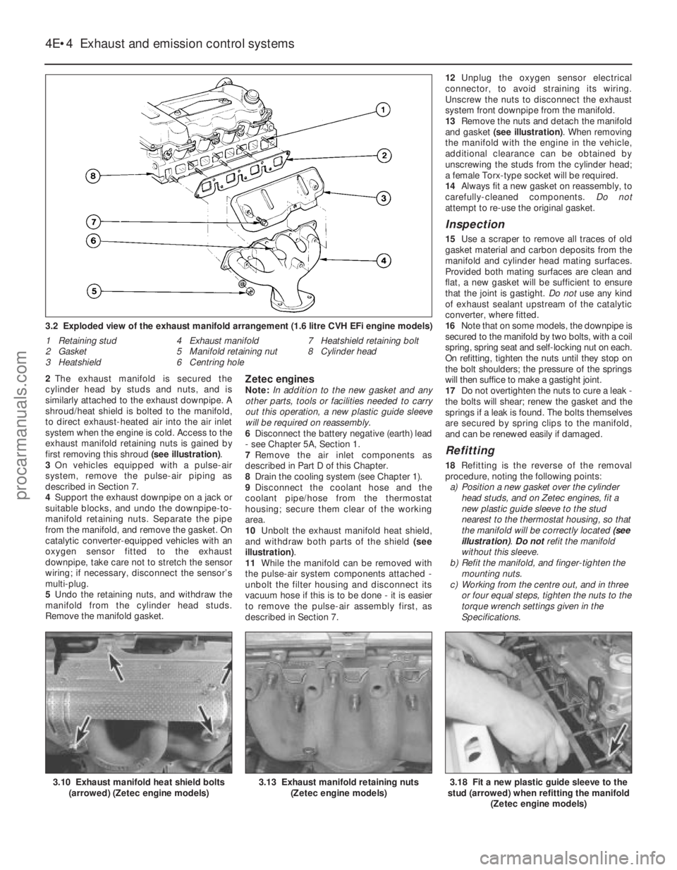
2The exhaust manifold is secured the
cylinder head by studs and nuts, and is
similarly attached to the exhaust downpipe. A
shroud/heat shield is bolted to the manifold,
to direct exhaust-heated air into the air inlet
system when the engine is cold. Access to the
exhaust manifold retaining nuts is gained by
first removing this shroud (see illustration).
3 On vehicles equipped with a pulse-air
system, remove the pulse-air piping as
described in Section 7.
4 Support the exhaust downpipe on a jack or
suitable blocks, and undo the downpipe-to-
manifold retaining nuts. Separate the pipe
from the manifold, and remove the gasket. On
catalytic converter-equipped vehicles with an
oxygen sensor fitted to the exhaust
downpipe, take care not to stretch the sensor
wiring; if necessary, disconnect the sensor’s
multi-plug.
5 Undo the retaining nuts, and withdraw the
manifold from the cylinder head studs.
Remove the manifold gasket.Zetec enginesNote: In addition to the new gasket and any
other parts, tools or facilities needed to carry
out this operation, a new plastic guide sleeve
will be required on reassembly.
6 Disconnect the battery negative (earth) lead
- see Chapter 5A, Section 1.
7 Remove the air inlet components as
described in Part D of this Chapter.
8 Drain the cooling system (see Chapter 1).
9 Disconnect the coolant hose and the
coolant pipe/hose from the thermostat
housing; secure them clear of the working
area.
10 Unbolt the exhaust manifold heat shield,
and withdraw both parts of the shield (see
illustration) .
11 While the manifold can be removed with
the pulse-air system components attached -
unbolt the filter housing and disconnect its
vacuum hose if this is to be done - it is easier
to remove the pulse-air assembly first, as
described in Section 7. 12
Unplug the oxygen sensor electrical
connector, to avoid straining its wiring.
Unscrew the nuts to disconnect the exhaust
system front downpipe from the manifold.
13 Remove the nuts and detach the manifold
and gasket (see illustration) . When removing
the manifold with the engine in the vehicle,
additional clearance can be obtained by
unscrewing the studs from the cylinder head;
a female Torx-type socket will be required.
14 Always fit a new gasket on reassembly, to
carefully-cleaned components. Do not
attempt to re-use the original gasket.
Inspection
15 Use a scraper to remove all traces of old
gasket material and carbon deposits from the
manifold and cylinder head mating surfaces.
Provided both mating surfaces are clean and
flat, a new gasket will be sufficient to ensure
that the joint is gastight. Do not use any kind
of exhaust sealant upstream of the catalytic
converter, where fitted.
16 Note that on some models, the downpipe is
secured to the manifold by two bolts, with a coil
spring, spring seat and self-locking nut on each.
On refitting, tighten the nuts until they stop on
the bolt shoulders; the pressure of the springs
will then suffice to make a gastight joint.
17 Do not overtighten the nuts to cure a leak -
the bolts will shear; renew the gasket and the
springs if a leak is found. The bolts themselves
are secured by spring clips to the manifold,
and can be renewed easily if damaged.
Refitting
18 Refitting is the reverse of the removal
procedure, noting the following points: a) Position a new gasket over the cylinder head studs, and on Zetec engines, fit a
new plastic guide sleeve to the stud
nearest to the thermostat housing, so that
the manifold will be correctly located (see
illustration) . Do notrefit the manifold
without this sleeve.
b) Refit the manifold, and finger-tighten the
mounting nuts.
c) Working from the centre out, and in three or four equal steps, tighten the nuts to the
torque wrench settings given in the
Specifications.
4E•4 Exhaust and emission control systems
3.18 Fit a new plastic guide sleeve to the
stud (arrowed) when refitting the manifold
(Zetec engine models)3.13 Exhaust manifold retaining nuts(Zetec engine models)3.10 Exhaust manifold heat shield bolts(arrowed) (Zetec engine models)
3.2 Exploded view of the exhaust manifold arrangement (1.6 litre CVH E\
Fi engine models)
1 Retaining stud
2 Gasket
3 Heatshield 4 Exhaust manifold
5 Manifold retaining nut
6 Centring hole 7 Heatshield retaining bolt
8 Cylinder head
1595Ford Fiesta Remakeprocarmanuals.com
http://vnx.su
Page 177 of 296
1 General information
The braking system is of the diagonally
split, dual-circuit hydraulic type, with servo
assistance to the front disc brakes and rear
drum brakes. The dual-circuit hydraulic
system is a safety feature - in the event of a
malfunction somewhere in one of the
hydraulic circuits, the other circuit continues
to operate, providing at least some braking
effort. Under normal circumstances, both
brake circuits operate in unison, to provide
efficient braking.
The master cylinder (and the vacuum servo
unit to which it is bolted) is located on the left-
hand side of the bulkhead in the engine
compartment. On all right-hand drive variants,
they are jointly operated via a transverse
cross-link from the brake pedal.
Brake pressure control valves are fitted in-
line to each rear brake circuit, their function
being to regulate the braking force available at
each rear wheel, reducing the possibility of
the rear wheels locking up under heavy
braking. Courier models also have a “light-
laden” valve incorporated into the rear braking
circuits for the same reason. The front brake discs are of the ventilated
type on XR2i and ABS-equipped models, with
solid discs fitted on all other models. The front
brake calipers are of single sliding piston type
mounted on the front spindle carriers each
side. Each rear brake shoe assembly is operated
by a twin-piston wheel cylinder. The leading
brake shoe in each brake unit has a thicker
lining than the trailing shoe, so that they wear
proportionally. To take up the brake
adjustment as the linings wear, each rear
brake assembly incorporates an automatic
adjuster mechanism. The cable-operated handbrake acts on
both rear brakes, to provide an independent
means of brake operation. An anti-lock braking system (ABS) is
available on some models, and has many of
the components in common with the conventional braking system. Further details
on ABS can be found later in this Chapter.
Note:
When servicing any part of the system,
work carefully and methodically; also observe
scrupulous cleanliness when overhauling any
part of the hydraulic system. Always renew
components (in axle sets, where applicable) if
in doubt about their condition, and use only
genuine Ford replacement parts, or at least
those of known good quality. Note the
warnings given in “Safety first” and at relevant
points in this Chapter concerning the dangers
of asbestos dust and hydraulic fluid.
2 Front brake pads - renewal
2
Warning: Disc brake pads MUST
be renewed on both front
wheels at the same time -
NEVER renew the pads on only
one wheel, as uneven braking may result.
The front brake calipers will be of Bendix
or Teves manufacture, and if they or their
component parts require renewal, ensure
that the correct type is fitted. Dust created
by wear of the pads may contain asbestos,
which is a health hazard. Never blow it out
with compressed air, and do not inhale any
of it. DO NOT use petroleum-based
solvents to clean brake parts - use brake
cleaner or methylated spirit only. DO NOT allow any brake fluid, oil or grease to
contact the brake pads or disc. Also refer
to the warning in Section 13 concerning
the dangers of hydraulic fluid.
1
Chock the rear wheels then jack up the
front of the car and support it on axle stands
(see “Jacking and Vehicle Support” ). Remove
the front roadwheels.
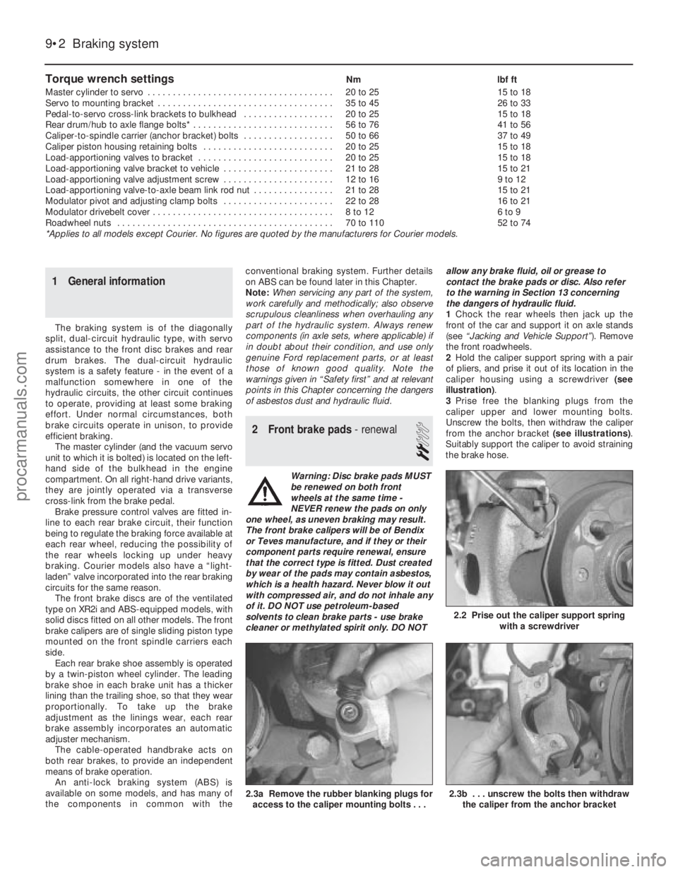
2 Hold the caliper support spring with a pair
of pliers, and prise it out of its location in the
caliper housing using a screwdriver (see
illustration) .
3 Prise free the blanking plugs from the
caliper upper and lower mounting bolts.
Unscrew the bolts, then withdraw the caliper
from the anchor bracket (see illustrations).
Suitably support the caliper to avoid straining
the brake hose.
Torque wrench settingsNm lbf ft
Master cylinder to servo . . . . . . . . . . . . . . . . . . . . . . . . . . . . . . . . . . . .\
. 20 to 25 15 to 18
Servo to mounting bracket . . . . . . . . . . . . . . . . . . . . . . . . . . . . . . . . . . . 35 to 45 26 to 33
Pedal-to-servo cross-link brackets to bulkhead . . . . . . . . . . . . . . . . . . 20 to 25 15 to 18
Rear drum/hub to axle flange bolts* . . . . . . . . . . . . . . . . . . . . . . . . . . . . 56 to 76 41 to 56
Caliper-to-spindle carrier (anchor bracket) bolts . . . . . . . . . . . . . . . . . . 50 to 66 37 to 49
Caliper piston housing retaining bolts . . . . . . . . . . . . . . . . . . . . . . . . . . 20 to 25 15 to 18
Load-apportioning valves to bracket . . . . . . . . . . . . . . . . . . . . . . . . . . . 20 to 25 15 to 18
Load-apportioning valve bracket to vehicle . . . . . . . . . . . . . . . . . . . . . . 21 to 28 15 to 21
Load-apportioning valve adjustment screw . . . . . . . . . . . . . . . . . . . . . . 12 to 16 9 to 12
Load-apportioning valve-to-axle beam link rod nut . . . . . . . . . . . . . . . . 21 to 28 15 to 21
Modulator pivot and adjusting clamp bolts . . . . . . . . . . . . . . . . . . . . . . 22 to 28 16 to 21
Modulator drivebelt cover . . . . . . . . . . . . . . . . . . . . . . . . . . . . . . . . . . . .\
8 to 12 6 to 9
Roadwheel nuts . . . . . . . . . . . . . . . . . . . . . . . . . . . . . . . . . . . .\
. . . . . . . 70 to 110 52 to 74
*Applies to all models except Courier. No figures are quoted by the manu\
facturers for Courier models.
9•2 Braking system
2.3b . . . unscrew the bolts then withdraw the caliper from the anchor bracket2.3a Remove the rubber blanking plugs foraccess to the caliper mounting bolts . . .
2.2 Prise out the caliper support spring with a screwdriver
1595Ford Fiesta Remakeprocarmanuals.com
http://vnx.su