1989 FORD FIESTA key battery
[x] Cancel search: key batteryPage 15 of 296
connections - remake the connections or
renew the leads if a fault is found. Use the
same techniques to ensure that all earth
points in the engine compartment provide
good electrical contact through clean, metal-
to-metal joints, and that all are securely
fastened. (In addition to the earth connection
at the engine lifting eye, and that from the
transmission to the body/battery, there are
others in various places, so check carefully).
8Refer to Section 21 for details of spark plug
(HT) lead checks.
7 Valve clearance adjustment
2
Refer to Chapter 2, Part A.
8 Manual transmission oil level check
1
1The manual transmission does not have a
dipstick. To check the oil level, raise the
vehicle and support it securely on axle stands,
making sure that the vehicle is level. On the
lower front side of the transmission housing,
you will see the filler/level plug. Unscrew and
remove it - an Allen key or bit will probably be
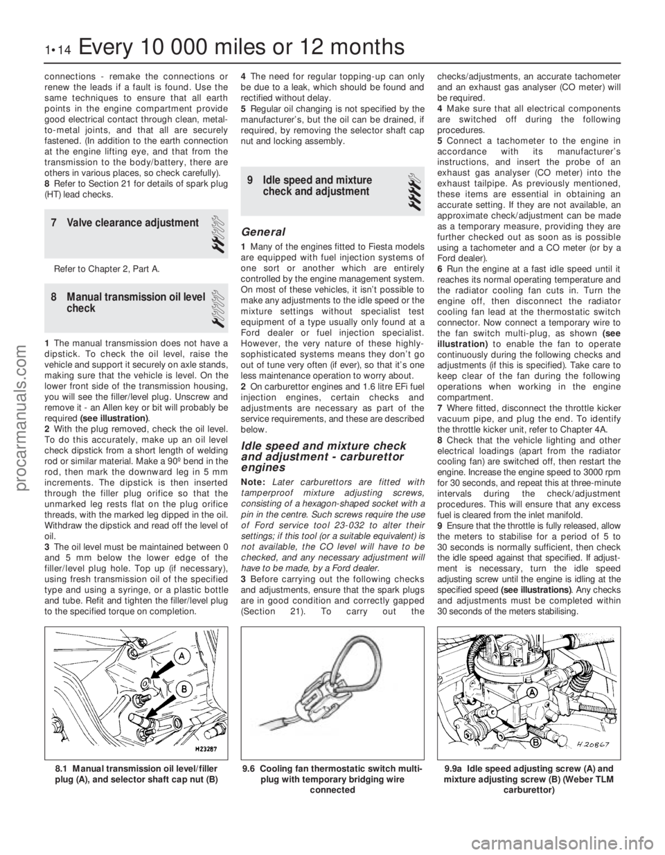
required (see illustration) .
2 With the plug removed, check the oil level.
To do this accurately, make up an oil level
check dipstick from a short length of welding
rod or similar material. Make a 90º bend in the
rod, then mark the downward leg in 5 mm
increments. The dipstick is then inserted
through the filler plug orifice so that the
unmarked leg rests flat on the plug orifice
threads, with the marked leg dipped in the oil.
Withdraw the dipstick and read off the level of
oil.
3 The oil level must be maintained between 0
and 5 mm below the lower edge of the
filler/level plug hole. Top up (if necessary),
using fresh transmission oil of the specified
type and using a syringe, or a plastic bottle
and tube. Refit and tighten the filler/level plug
to the specified torque on completion. 4
The need for regular topping-up can only
be due to a leak, which should be found and
rectified without delay.
5 Regular oil changing is not specified by the
manufacturer’s, but the oil can be drained, if
required, by removing the selector shaft cap
nut and locking assembly.
9 Idle speed and mixture check and adjustment
4
General
1Many of the engines fitted to Fiesta models
are equipped with fuel injection systems of
one sort or another which are entirely
controlled by the engine management system.
On most of these vehicles, it isn’t possible to
make any adjustments to the idle speed or the
mixture settings without specialist test
equipment of a type usually only found at a
Ford dealer or fuel injection specialist.
However, the very nature of these highly-
sophisticated systems means they don’t go
out of tune very often (if ever), so that it’s one
less maintenance operation to worry about.
2 On carburettor engines and 1.6 litre EFi fuel
injection engines, certain checks and
adjustments are necessary as part of the
service requirements, and these are described
below.
Idle speed and mixture check
and adjustment - carburettor
engines
Note: Later carburettors are fitted with
tamperproof mixture adjusting screws,
consisting of a hexagon-shaped socket with a
pin in the centre. Such screws require the use
of Ford service tool 23-032 to alter their
settings; if this tool (or a suitable equivalent) is
not available, the CO level will have to be
checked, and any necessary adjustment will
have to be made, by a Ford dealer.
3 Before carrying out the following checks
and adjustments, ensure that the spark plugs
are in good condition and correctly gapped
(Section 21). To carry out the checks/adjustments, an accurate tachometer
and an exhaust gas analyser (CO meter) will
be required.
4
Make sure that all electrical components
are switched off during the following
procedures.
5 Connect a tachometer to the engine in
accordance with its manufacturer’s
instructions, and insert the probe of an
exhaust gas analyser (CO meter) into the
exhaust tailpipe. As previously mentioned,
these items are essential in obtaining an
accurate setting. If they are not available, an
approximate check/adjustment can be made
as a temporary measure, providing they are
further checked out as soon as is possible
using a tachometer and a CO meter (or by a
Ford dealer).
6 Run the engine at a fast idle speed until it
reaches its normal operating temperature and
the radiator cooling fan cuts in. Turn the
engine off, then disconnect the radiator
cooling fan lead at the thermostatic switch
connector. Now connect a temporary wire to
the fan switch multi-plug, as shown (see
illustration) to enable the fan to operate
continuously during the following checks and
adjustments (if this is specified). Take care to
keep clear of the fan during the following
operations when working in the engine
compartment.
7 Where fitted, disconnect the throttle kicker
vacuum pipe, and plug the end. To identify
the throttle kicker unit, refer to Chapter 4A.
8 Check that the vehicle lighting and other
electrical loadings (apart from the radiator
cooling fan) are switched off, then restart the
engine. Increase the engine speed to 3000 rpm
for 30 seconds, and repeat this at three-minute
intervals during the check/adjustment
procedures. This will ensure that any excess
fuel is cleared from the inlet manifold.
9 Ensure that the throttle is fully released, allow
the meters to stabilise for a period of 5 to
30 seconds is normally sufficient, then check
the idle speed against that specified. If adjust-
ment is necessary, turn the idle speed
adjusting screw until the engine is idling at the
specified speed (see illustrations) . Any checks
and adjustments must be completed within
30 seconds of the meters stabilising.
1•14Every 10 000 miles or 12 months
9.9a Idle speed adjusting screw (A) and
mixture adjusting screw (B) (Weber TLM
carburettor)9.6 Cooling fan thermostatic switch multi-plug with temporary bridging wire
connected8.1 Manual transmission oil level/filler
plug (A), and selector shaft cap nut (B)
1595Ford Fiesta Remakeprocarmanuals.com
http://vnx.su
Page 45 of 296
of the crankshaft sprocket, and then pull the
belt vertically upright on its right-hand run.
Keep it taut, and engage it with the teeth of
the camshaft sprocket. If the original belt is
being refitted, check that the belt’s direction
of travel is correct, and realign the belt-to-
sprocket marks made during removal, to
ensure that the exact original engagement
positions are retained. When the belt is fully
fitted on the sprockets, check that the
sprocket positions have not altered.
9Carefully manoeuvre the belt around the
tensioner, and engage its teeth with the water
pump sprocket, again ensuring that the TDC
positions of the crankshaft and camshaft
are not disturbed as the belt is finally
located.
10 Refit the lower timing belt cover, and
tighten its retaining bolts to the specified
torque setting. Refit the crankshaft pulley, and
tighten its retaining bolt to the specified
torque setting.
11 To take up belt slack, loosen off the
tensioner and move it towards the front of the
car to apply an initial tension to the belt.
Secure the tensioner in this position, then
remove the flywheel ring gear locking device.
12 Rotate the crankshaft through two full
revolutions in (the normal direction of travel),
returning to the TDC position (camshaft
sprocket-to-cylinder head). Check that the
crankshaft pulley notch is aligned with the
TDC (0) mark on the lower half of the timing
belt cover.
13 Grasp the belt between the thumb and
forefinger, at the midway point between the
crankshaft and camshaft sprockets on the
right-hand side. If the belt tension is correct, it
should just be possible to twist the belt
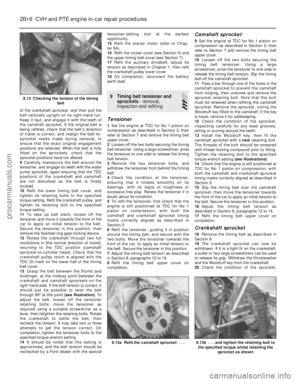
through 90º at this point (see illustration). To
adjust the belt, loosen off the tensioner
retaining bolts, move the tensioner as
required using a suitable screwdriver as a
lever, then retighten the retaining bolts. Rotate
the crankshaft to settle the belt, then
recheck the tension. It may take two or three
attempts to get the tension correct. On
completion, tighten the tensioner bolts to the
specified torque wrench setting.
14 It should be noted that this setting is
approximate, and the belt tension should be
rechecked by a Ford dealer with the special tensioner-setting tool at the earliest
opportunity.
15
Refit the starter motor (refer to Chap-
ter 5A).
16 Refit the rocker cover (see Section 4) and
the upper timing belt cover (see Section 7).
17 Refit the auxiliary drivebelt, adjust its
tension as described in Chapter 1, then refit
the crankshaft pulley lower cover.
18 On completion, reconnect the battery
earth lead.
9 Timing belt tensioner and sprockets - removal,
inspection and refitting
3
Tensioner
1 Set the engine at TDC for No 1 piston on
compression as described in Section 3, then
refer to Section 7 and remove the timing belt
upper cover.
2 Loosen off the two bolts securing the timing
belt tensioner. Using a large screwdriver, prise
the tensioner to one side to release the timing
belt tension.
3 Remove the two tensioner bolts, and
withdraw the tensioner from behind the timing
belt.
4 Check the condition of the tensioner,
ensuring that it rotates smoothly on its
bearings, with no signs of roughness or
excessive free play. Renew the tensioner if in
doubt about its condition.
5 To refit the tensioner, first check that the
engine is still positioned at TDC for No 1
piston on compression, with both the
camshaft and crankshaft sprocket timing
marks correctly aligned as described in
Section 3.
6 Refit the tensioner, guiding it in position
around the timing belt, and secure with the
two bolts. Move the tensioner towards the
front of the car, to apply an initial tension to
the belt. Secure the tensioner in this position.
7 Adjust the timing belt tension as described
in Section 8, paragraphs 12 to 14.
8 Refit the timing belt upper cover on
completion.
Camshaft sprocket
9 Set the engine at TDC for No 1 piston on
compression as described in Section 3, then
refer to Section 7 and remove the timing belt
upper cover.
10 Loosen off the two bolts securing the
timing belt tensioner. Using a large
screwdriver, prise the tensioner to one side to
release the timing belt tension. Slip the timing
belt off the camshaft sprocket.
11 Pass a bar through one of the holes in the
camshaft sprocket to prevent the camshaft
from rotating, then unscrew and remove the
sprocket retaining bolt. Note that this bolt
must be renewed when refitting the camshaft
sprocket. Remove the sprocket, noting the
Woodruff key fitted to the camshaft; if the key
is loose, remove it for safekeeping.
12 Check the condition of the sprocket,
inspecting carefully for any wear grooves,
pitting or scoring around the teeth.
13 Install the Woodruff key, then fit the
camshaft sprocket with a newretaining bolt.
The threads of the bolt should be smeared
with thread-locking compound prior to fitting.
Tighten the retaining bolt to the specified
torque wrench setting (see illustrations).
14 Check that the engine is still positioned at
TDC for No 1 piston on compression, with
both the camshaft and crankshaft sprocket
timing marks correctly aligned as described in
Section 3.
15 Slip the timing belt over the camshaft
sprocket, then move the tensioner towards
the front of the car to apply an initial tension to
the belt. Secure the tensioner in this position.
16 Adjust the timing belt tension as
described in Section 8, paragraphs 12 to 14.
17 Refit the timing belt upper cover on
completion.
Crankshaft sprocket
18 Remove the timing belt as described in
Section 8.
19 The crankshaft sprocket can now be
withdrawn. If it is a tight fit on the crankshaft,
a puller or two large screwdrivers can be used
to release its grip. Withdraw the thrustwasher
and the Woodruff key from the crankshaft.
20 Check the condition of the sprocket,
2B•6 CVH and PTE engine in-car repair procedures
9.13b . . . and tighten the retaining bolt to
the specified torque whilst retaining the
sprocket as shown9.13a Refit the camshaft sprocket . . .
8.13 Checking the tension of the timing belt
1595Ford Fiesta Remakeprocarmanuals.com
http://vnx.su
Page 46 of 296
inspecting carefully for any wear grooves,
pitting or scoring around the teeth.
21Refit the thrustwasher with its curved side
facing outwards, followed by the Woodruff
key.
22 Lubricate the oil seal and the crankshaft
sprocket with engine oil, then position the
sprocket on the crankshaft with its thrust face
facing outwards.
23 Using the auxiliary drivebelt pulley and its
retaining bolt, draw the sprocket fully into
position on the crankshaft. Remove the
pulley.
24 Refit the timing belt as described in
Section 8.
10 Camshaft oil seal - renewal
3
1Remove the camshaft sprocket as
described in the previous Section.
2 The oil seal is now accessible for removal.
Note its direction of fitting, then using a
suitable screwdriver or a tool with a hooked
end to lever and extract the seal from its
housing (but take care not to damage the
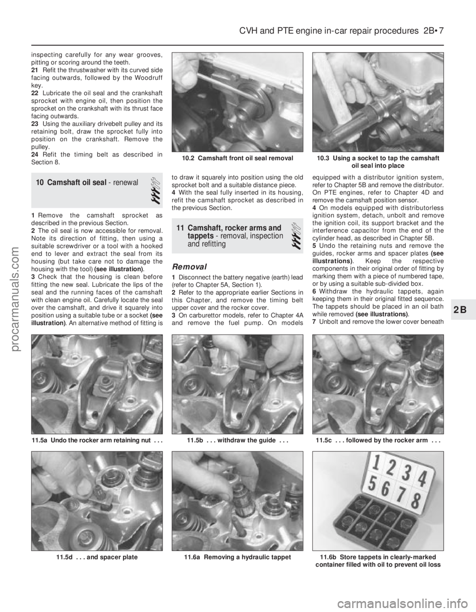
housing with the tool) (see illustration).
3 Check that the housing is clean before
fitting the new seal. Lubricate the lips of the
seal and the running faces of the camshaft
with clean engine oil. Carefully locate the seal
over the camshaft, and drive it squarely into
position using a suitable tube or a socket (see
illustration) . An alternative method of fitting is to draw it squarely into position using the old
sprocket bolt and a suitable distance piece.
4
With the seal fully inserted in its housing,
refit the camshaft sprocket as described in
the previous Section.
11 Camshaft, rocker arms and tappets - removal, inspection
and refitting
3
Removal
1 Disconnect the battery negative (earth) lead
(refer to Chapter 5A, Section 1).
2 Refer to the appropriate earlier Sections in
this Chapter, and remove the timing belt
upper cover and the rocker cover.
3 On carburettor models, refer to Chapter 4A
and remove the fuel pump. On models equipped with a distributor ignition system,
refer to Chapter 5B and remove the distributor.
On PTE engines, refer to Chapter 4D and
remove the camshaft position sensor.
4
On models equipped with distributorless
ignition system, detach, unbolt and remove
the ignition coil, its support bracket and the
interference capacitor from the end of the
cylinder head, as described in Chapter 5B.
5 Undo the retaining nuts and remove the
guides, rocker arms and spacer plates (see
illustrations) . Keep the respective
components in their original order of fitting by
marking them with a piece of numbered tape,
or by using a suitable sub-divided box.
6 Withdraw the hydraulic tappets, again
keeping them in their original fitted sequence.
The tappets should be placed in an oil bath
while removed (see illustrations) .
7 Unbolt and remove the lower cover beneath
CVH and PTE engine in-car repair procedures 2B•7
11.5a Undo the rocker arm retaining nut . . .
10.3 Using a socket to tap the camshaft
oil seal into place
11.6b Store tappets in clearly-marked
container filled with oil to prevent oil loss11.6a Removing a hydraulic tappet
11.5c . . . followed by the rocker arm . . .11.5b . . . withdraw the guide . . .
11.5d . . . and spacer plate
10.2 Camshaft front oil seal removal
2B
1595Ford Fiesta Remakeprocarmanuals.com
http://vnx.su
Page 50 of 296
bolt(s) securing the gearchange mechanism
stabiliser bar/exhaust forward mounting
bracket (where fitted) and ease it out of the
way.
7Remove the starter motor as described in
Chapter 5A, then undo the retaining bolts, and
remove the clutch cover plate from the front
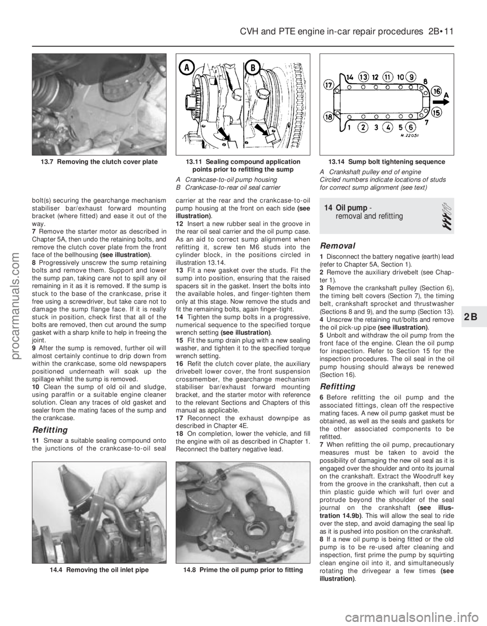
face of the bellhousing (see illustration).
8 Progressively unscrew the sump retaining
bolts and remove them. Support and lower
the sump pan, taking care not to spill any oil
remaining in it as it is removed. If the sump is
stuck to the base of the crankcase, prise it
free using a screwdriver, but take care not to
damage the sump flange face. If it is really
stuck in position, check first that all of the
bolts are removed, then cut around the sump
gasket with a sharp knife to help in freeing the
joint.
9 After the sump is removed, further oil will
almost certainly continue to drip down from
within the crankcase, some old newspapers
positioned underneath will soak up the
spillage whilst the sump is removed.
10 Clean the sump of old oil and sludge,
using paraffin or a suitable engine cleaner
solution. Clean any traces of old gasket and
sealer from the mating faces of the sump and
the crankcase.
Refitting
11 Smear a suitable sealing compound onto
the junctions of the crankcase-to-oil seal carrier at the rear and the crankcase-to-oil
pump housing at the front on each side
(see
illustration) .
12 Insert a new rubber seal in the groove in
the rear oil seal carrier and the oil pump case.
As an aid to correct sump alignment when
refitting it, screw ten M6 studs into the
cylinder block, in the positions circled in
illustration 13.14.
13 Fit a new gasket over the studs. Fit the
sump into position, ensuring that the raised
spacers sit in the gasket. Insert the bolts into
the available holes, and finger-tighten them
only at this stage. Now remove the studs and
fit the remaining bolts, again finger-tight.
14 Tighten the sump bolts in a progressive,
numerical sequence to the specified torque
wrench setting (see illustration) .
15 Fit the sump drain plug with a new sealing
washer, and tighten it to the specified torque
wrench setting.
16 Refit the clutch cover plate, the auxiliary
drivebelt lower cover, the front suspension
crossmember, the gearchange mechanism
stabiliser bar/exhaust forward mounting
bracket, and the starter motor with reference
to the relevant Sections and Chapters of this
manual as applicable.
17 Reconnect the exhaust downpipe as
described in Chapter 4E.
18 On completion, lower the vehicle, and fill
the engine with oil as described in Chapter 1.
Reconnect the battery negative lead.
14 Oil pump -
removal and refitting
3
Removal
1 Disconnect the battery negative (earth) lead
(refer to Chapter 5A, Section 1).
2 Remove the auxiliary drivebelt (see Chap-
ter 1).
3 Remove the crankshaft pulley (Section 6),
the timing belt covers (Section 7), the timing
belt, crankshaft sprocket and thrustwasher
(Sections 8 and 9), and the sump (Section 13).
4 Unscrew the retaining nut/bolts and remove
the oil pick-up pipe (see illustration).
5 Unbolt and withdraw the oil pump from the
front face of the engine. Clean the oil pump
for inspection. Refer to Section 15 for the
inspection procedures. The oil seal in the oil
pump housing should always be renewed
(Section 16).
Refitting
6 Before refitting the oil pump and the
associated fittings, clean off the respective
mating faces. A new oil pump gasket must be
obtained, as well as the seals and gaskets for
the other associated components to be
refitted.
7 When refitting the oil pump, precautionary
measures must be taken to avoid the
possibility of damaging the new oil seal as it is
engaged over the shoulder and onto its journal
on the crankshaft. Extract the Woodruff key
from the groove in the crankshaft, then cut a
thin plastic guide which will furl over and
protrude beyond the shoulder of the seal
journal on the crankshaft (see illus-
tration 14.9b) . This will allow the seal to ride
over the step, and avoid damaging the seal lip
as it is pushed into position on the crankshaft.
8 If a new oil pump is being fitted or the old
pump is to be re-used after cleaning and
inspection, first prime the pump by squirting
clean engine oil into it, and simultaneously
rotating the drivegear a few times (see
illustration) .
CVH and PTE engine in-car repair procedures 2B•11
13.14 Sump bolt tightening sequence
A Crankshaft pulley end of engine
Circled numbers indicate locations of studs
for correct sump alignment (see text)13.11 Sealing compound application points prior to refitting the sump
A Crankcase-to-oil pump housing
B Crankcase-to-rear oil seal carrier13.7 Removing the clutch cover plate
14.8 Prime the oil pump prior to fitting14.4 Removing the oil inlet pipe
2B
1595Ford Fiesta Remakeprocarmanuals.com
http://vnx.su
Page 51 of 296
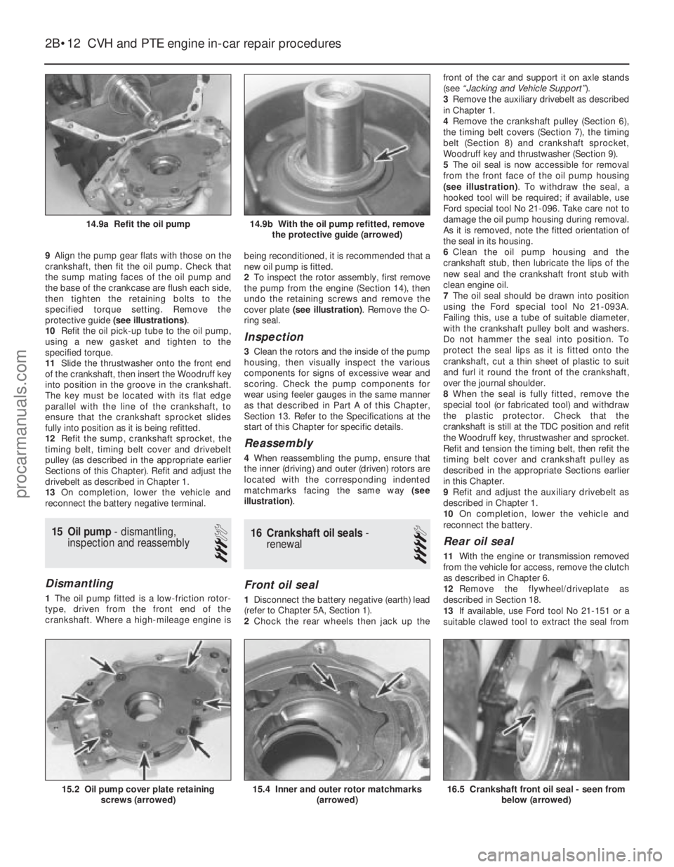
9Align the pump gear flats with those on the
crankshaft, then fit the oil pump. Check that
the sump mating faces of the oil pump and
the base of the crankcase are flush each side,
then tighten the retaining bolts to the
specified torque setting. Remove the
protective guide (see illustrations) .
10 Refit the oil pick-up tube to the oil pump,
using a new gasket and tighten to the
specified torque.
11 Slide the thrustwasher onto the front end
of the crankshaft, then insert the Woodruff key
into position in the groove in the crankshaft.
The key must be located with its flat edge
parallel with the line of the crankshaft, to
ensure that the crankshaft sprocket slides
fully into position as it is being refitted.
12 Refit the sump, crankshaft sprocket, the
timing belt, timing belt cover and drivebelt
pulley (as described in the appropriate earlier
Sections of this Chapter). Refit and adjust the
drivebelt as described in Chapter 1.
13 On completion, lower the vehicle and
reconnect the battery negative terminal.
15 Oil pump - dismantling,
inspection and reassembly
3
Dismantling
1 The oil pump fitted is a low-friction rotor-
type, driven from the front end of the
crankshaft. Where a high-mileage engine is being reconditioned, it is recommended that a
new oil pump is fitted.
2
To inspect the rotor assembly, first remove
the pump from the engine (Section 14), then
undo the retaining screws and remove the
cover plate (see illustration) . Remove the O-
ring seal.
Inspection
3 Clean the rotors and the inside of the pump
housing, then visually inspect the various
components for signs of excessive wear and
scoring. Check the pump components for
wear using feeler gauges in the same manner
as that described in Part A of this Chapter,
Section 13. Refer to the Specifications at the
start of this Chapter for specific details.
Reassembly
4 When reassembling the pump, ensure that
the inner (driving) and outer (driven) rotors are
located with the corresponding indented
matchmarks facing the same way (see
illustration) .
16Crankshaft oil seals -
renewal
4
Front oil seal
1 Disconnect the battery negative (earth) lead
(refer to Chapter 5A, Section 1).
2 Chock the rear wheels then jack up the front of the car and support it on axle stands
(see
“Jacking and Vehicle Support” ).
3 Remove the auxiliary drivebelt as described
in Chapter 1.
4 Remove the crankshaft pulley (Section 6),
the timing belt covers (Section 7), the timing
belt (Section 8) and crankshaft sprocket,
Woodruff key and thrustwasher (Section 9).
5 The oil seal is now accessible for removal
from the front face of the oil pump housing
(see illustration) . To withdraw the seal, a
hooked tool will be required; if available, use
Ford special tool No 21-096. Take care not to
damage the oil pump housing during removal.
As it is removed, note the fitted orientation of
the seal in its housing.
6 Clean the oil pump housing and the
crankshaft stub, then lubricate the lips of the
new seal and the crankshaft front stub with
clean engine oil.
7 The oil seal should be drawn into position
using the Ford special tool No 21-093A.
Failing this, use a tube of suitable diameter,
with the crankshaft pulley bolt and washers.
Do not hammer the seal into position. To
protect the seal lips as it is fitted onto the
crankshaft, cut a thin sheet of plastic to suit
and furl it round the front of the crankshaft,
over the journal shoulder.
8 When the seal is fully fitted, remove the
special tool (or fabricated tool) and withdraw
the plastic protector. Check that the
crankshaft is still at the TDC position and refit
the Woodruff key, thrustwasher and sprocket.
Refit and tension the timing belt, then refit the
timing belt cover and crankshaft pulley as
described in the appropriate Sections earlier
in this Chapter.
9 Refit and adjust the auxiliary drivebelt as
described in Chapter 1.
10 On completion, lower the vehicle and
reconnect the battery.
Rear oil seal
11 With the engine or transmission removed
from the vehicle for access, remove the clutch
as described in Chapter 6.
12 Remove the flywheel/driveplate as
described in Section 18.
13 If available, use Ford tool No 21-151 or a
suitable clawed tool to extract the seal from
2B•12 CVH and PTE engine in-car repair procedures
16.5 Crankshaft front oil seal - seen from
below (arrowed)15.4 Inner and outer rotor matchmarks (arrowed)15.2 Oil pump cover plate retainingscrews (arrowed)
14.9b With the oil pump refitted, removethe protective guide (arrowed)14.9a Refit the oil pump
1595Ford Fiesta Remakeprocarmanuals.com
http://vnx.su
Page 137 of 296
11On non-Turbo models, disconnect the
flexible hose between the air cleaner lid and
the air inlet duct.
12 On Turbo models, disconnect the idle
speed control valve air bypass hose from the
air inlet duct and the flexible hose between
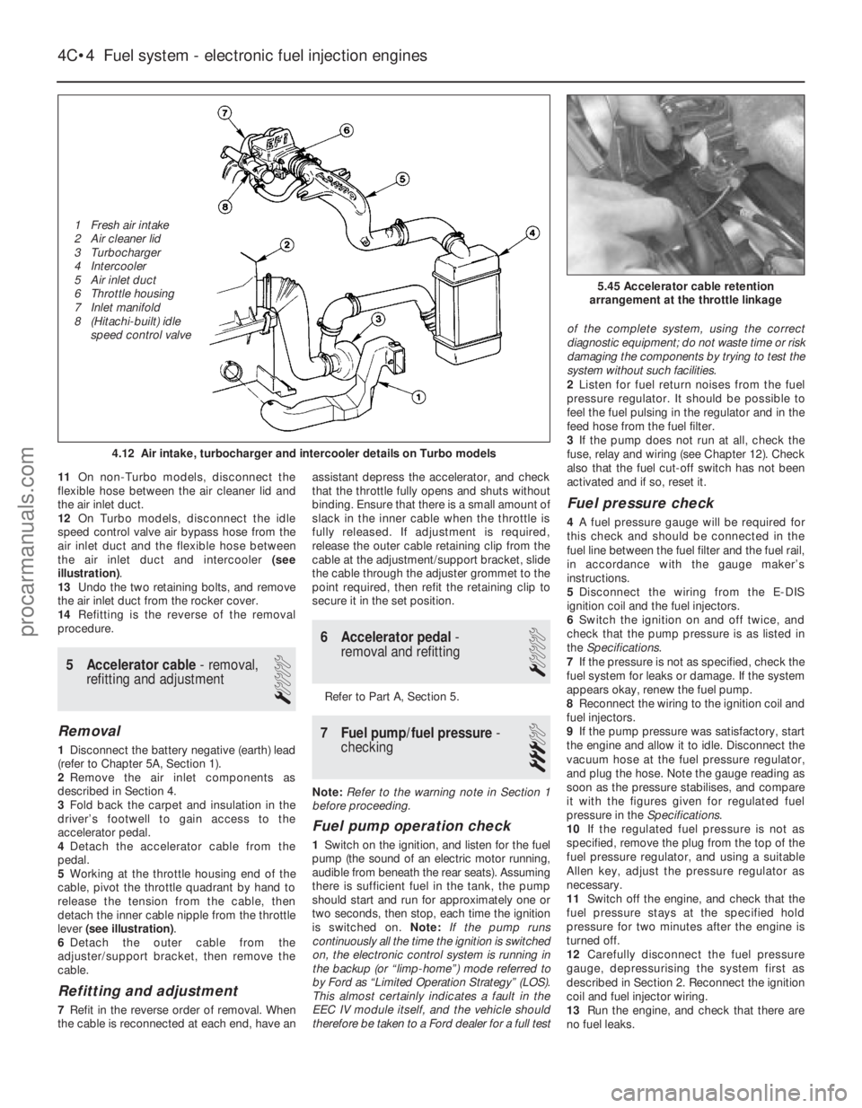
the air inlet duct and intercooler (see
illustration) .
13 Undo the two retaining bolts, and remove
the air inlet duct from the rocker cover.
14 Refitting is the reverse of the removal
procedure.
5 Accelerator cable - removal,
refitting and adjustment
1
Removal
1 Disconnect the battery negative (earth) lead
(refer to Chapter 5A, Section 1).
2 Remove the air inlet components as
described in Section 4.
3 Fold back the carpet and insulation in the
driver’s footwell to gain access to the
accelerator pedal.
4 Detach the accelerator cable from the
pedal.
5 Working at the throttle housing end of the
cable, pivot the throttle quadrant by hand to
release the tension from the cable, then
detach the inner cable nipple from the throttle
lever (see illustration) .
6 Detach the outer cable from the
adjuster/support bracket, then remove the
cable.
Refitting and adjustment
7 Refit in the reverse order of removal. When
the cable is reconnected at each end, have an assistant depress the accelerator, and check
that the throttle fully opens and shuts without
binding. Ensure that there is a small amount of
slack in the inner cable when the throttle is
fully released. If adjustment is required,
release the outer cable retaining clip from the
cable at the adjustment/support bracket, slide
the cable through the adjuster grommet to the
point required, then refit the retaining clip to
secure it in the set position.
6 Accelerator pedal
-
removal and refitting
1
Refer to Part A, Section 5.
7 Fuel pump/fuel pressure -
checking
3
Note: Refer to the warning note in Section 1
before proceeding.
Fuel pump operation check
1 Switch on the ignition, and listen for the fuel
pump (the sound of an electric motor running,
audible from beneath the rear seats). Assuming
there is sufficient fuel in the tank, the pump
should start and run for approximately one or
two seconds, then stop, each time the ignition
is switched on. Note:If the pump runs
continuously all the time the ignition is switched
on, the electronic control system is running in
the backup (or “limp-home”) mode referred to
by Ford as “Limited Operation Strategy” (LOS).
This almost certainly indicates a fault in the
EEC IV module itself, and the vehicle should
therefore be taken to a Ford dealer for a full test of the complete system, using the correct
diagnostic equipment; do not waste time or risk
damaging the components by trying to test the
system without such facilities.
2
Listen for fuel return noises from the fuel
pressure regulator. It should be possible to
feel the fuel pulsing in the regulator and in the
feed hose from the fuel filter.
3 If the pump does not run at all, check the
fuse, relay and wiring (see Chapter 12). Check
also that the fuel cut-off switch has not been
activated and if so, reset it.
Fuel pressure check
4 A fuel pressure gauge will be required for
this check and should be connected in the
fuel line between the fuel filter and the fuel rail,
in accordance with the gauge maker’s
instructions.
5 Disconnect the wiring from the E-DIS
ignition coil and the fuel injectors.
6 Switch the ignition on and off twice, and
check that the pump pressure is as listed in
the Specifications .
7 If the pressure is not as specified, check the
fuel system for leaks or damage. If the system
appears okay, renew the fuel pump.
8 Reconnect the wiring to the ignition coil and
fuel injectors.
9 If the pump pressure was satisfactory, start
the engine and allow it to idle. Disconnect the
vacuum hose at the fuel pressure regulator,
and plug the hose. Note the gauge reading as
soon as the pressure stabilises, and compare
it with the figures given for regulated fuel
pressure in the Specifications.
10 If the regulated fuel pressure is not as
specified, remove the plug from the top of the
fuel pressure regulator, and using a suitable
Allen key, adjust the pressure regulator as
necessary.
11 Switch off the engine, and check that the
fuel pressure stays at the specified hold
pressure for two minutes after the engine is
turned off.
12 Carefully disconnect the fuel pressure
gauge, depressurising the system first as
described in Section 2. Reconnect the ignition
coil and fuel injector wiring.
13 Run the engine, and check that there are
no fuel leaks.
4C•4 Fuel system - electronic fuel injection engines
5.45 Accelerator cable retention
arrangement at the throttle linkage
4.12 Air intake, turbocharger and intercooler details on Turbo models
1595Ford Fiesta Remake
1 Fresh air intake
2 Air cleaner lid
3 Turbocharger
4 Intercooler
5 Air inlet duct
6 Throttle housing
7 Inlet manifold
8 (Hitachi-built) idle
speed control valveprocarmanuals.com
http://vnx.su
Page 160 of 296
5A
1595Ford Fiesta Remake
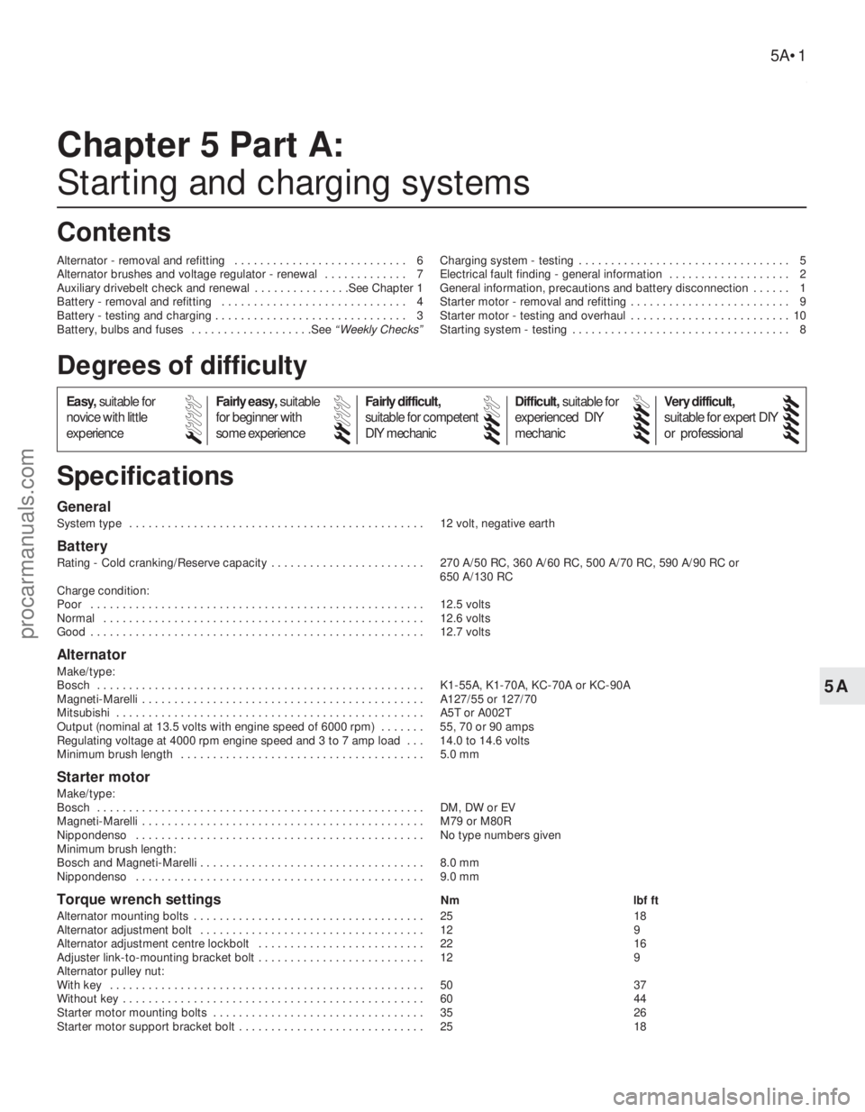
General
System type . . . . . . . . . . . . . . . . . . . . . . . . . . . . . . . . . . . .\
. . . . . . . . . . 12 volt, negative earth
Battery
Rating - Cold cranking/Reserve capacity . . . . . . . . . . . . . . . . . . . . . . . . 270 A/50 RC, 360 A/60 RC, 500 A/70 RC, 590 A/90 RC or 650 A/130 RC
Charge condition:
Poor . . . . . . . . . . . . . . . . . . . . . . . . . . . . . . . . . . . .\
. . . . . . . . . . . . . . . . 12.5 volts
Normal . . . . . . . . . . . . . . . . . . . . . . . . . . . . . . . . . . . .\
. . . . . . . . . . . . . . 12.6 volts
Good . . . . . . . . . . . . . . . . . . . . . . . . . . . . . . . . . . . .\
. . . . . . . . . . . . . . . . 12.7 volts
Alternator
Make/type:
Bosch . . . . . . . . . . . . . . . . . . . . . . . . . . . . . . . . . . . .\
. . . . . . . . . . . . . . . K1-55A, K1-70A, KC-70A or KC-90A
Magneti-Marelli . . . . . . . . . . . . . . . . . . . . . . . . . . . . . . . . . . . .\
. . . . . . . . A127/55 or 127/70
Mitsubishi . . . . . . . . . . . . . . . . . . . . . . . . . . . . . . . . . . . .\
. . . . . . . . . . . . A5T or A002T
Output (nominal at 13.5 volts with engine speed of 6000 rpm) . . . . . . . 55, 70 or 90 amps
Regulating voltage at 4000 rpm engine speed and 3 to 7 amp load . . . 14.0 to 14.6 volts
Minimum brush length . . . . . . . . . . . . . . . . . . . . . . . . . . . . . . . . . . . .\
. . 5.0 mm
Starter motor
Make/type:
Bosch . . . . . . . . . . . . . . . . . . . . . . . . . . . . . . . . . . . .\
. . . . . . . . . . . . . . . DM, DW or EV
Magneti-Marelli . . . . . . . . . . . . . . . . . . . . . . . . . . . . . . . . . . . .\
. . . . . . . . M79 or M80R
Nippondenso . . . . . . . . . . . . . . . . . . . . . . . . . . . . . . . . . . . .\
. . . . . . . . . No type numbers given
Minimum brush length:
Bosch and Magneti-Marelli . . . . . . . . . . . . . . . . . . . . . . . . . . . . . . . . . . . 8.0 mm
Nippondenso . . . . . . . . . . . . . . . . . . . . . . . . . . . . . . . . . . . .\
. . . . . . . . . 9.0 mm
Torque wrench settingsNm lbf ft
Alternator mounting bolts . . . . . . . . . . . . . . . . . . . . . . . . . . . . . . . . . . . .\
25 18
Alternator adjustment bolt . . . . . . . . . . . . . . . . . . . . . . . . . . . . . . . . . . . 12 9
Alternator adjustment centre lockbolt . . . . . . . . . . . . . . . . . . . . . . . . . . 22 16
Adjuster link-to-mounting bracket bolt . . . . . . . . . . . . . . . . . . . . . . . . . . 12 9
Alternator pulley nut:
With key . . . . . . . . . . . . . . . . . . . . . . . . . . . . . . . . . . . .\
. . . . . . . . . . . . . 50 37
Without key . . . . . . . . . . . . . . . . . . . . . . . . . . . . . . . . . . . .\
. . . . . . . . . . . 60 44
Starter motor mounting bolts . . . . . . . . . . . . . . . . . . . . . . . . . . . . . . . . . 35 26
Starter motor support bracket bolt . . . . . . . . . . . . . . . . . . . . . . . . . . . . . 25 18
Chapter 5 Part A:
Starting and charging systems
Alternator - removal and refitting . . . . . . . . . . . . . . . . . . . . . . . . . . . 6
Alternator brushes and voltage regulator - renewal . . . . . . . . . . . . . 7
Auxiliary drivebelt check and renewal . . . . . . . . . . . . . . .See Chapter 1
Battery - removal and refitting . . . . . . . . . . . . . . . . . . . . . . . . . . . . . 4
Battery - testing and charging . . . . . . . . . . . . . . . . . . . . . . . . . . . . . . 3
Battery, bulbs and fuses . . . . . . . . . . . . . . . . . . .See
“Weekly Checks” Charging system - testing . . . . . . . . . . . . . . . . . . . . . . . . . . . . . . . . . 5
Electrical fault finding - general information . . . . . . . . . . . . . . . . . . . 2
General information, precautions and battery disconnection . . . . . . 1
Starter motor - removal and refitting . . . . . . . . . . . . . . . . . . . . . . . . . 9
Starter motor - testing and overhaul . . . . . . . . . . . . . . . . . . . . . . . . . 10
Starting system - testing . . . . . . . . . . . . . . . . . . . . . . . . . . . . . . . . . . 8
5A•1
Specifications Contents
Easy,
suitable for
novice with little
experience Fairly easy,
suitable
for beginner with
some experience Fairly difficult,
suitable for competent
DIY mechanic
Difficult,
suitable for
experienced DIY
mechanic Very difficult,
suitable for expert DIY
or professional
Degrees of difficulty
54321
procarmanuals.com
http://vnx.su
Page 161 of 296
1 General information,precautions and battery
disconnection
General information
The engine electrical system consists
mainly of the charging and starting systems.
Because of their engine-related functions,
these components are covered separately
from the body electrical devices such as the
lights, instruments, etc (which are covered in
Chapter 12). Information on the ignition
system is covered in Part B of this Chapter.
The electrical system is of the 12-volt
negative earth type. The battery is of the low maintenance or
“maintenance-free” (sealed for life) type and is
charged by the alternator, which is belt-driven
from the crankshaft pulley. The starter motor is of the pre-engaged
type incorporating an integral solenoid. On
starting, the solenoid moves the drive pinion
into engagement with the flywheel ring gear
before the starter motor is energised. Once
the engine has started, a one-way clutch
prevents the motor armature being driven by
the engine until the pinion disengages from
the flywheel.
Precautions
Further details of the various systems are
given in the relevant Sections of this Chapter.
While some repair procedures are given, the
usual course of action is to renew the
component concerned. The owner whose
interest extends beyond mere component
renewal should obtain a copy of the
“Automobile Electrical & Electronic Systems
Manual” , available from the publishers of this
manual. It is necessary to take extra care when
working on the electrical system to avoid
damage to semi-conductor devices (diodes
and transistors), and to avoid the risk of
personal injury. In addition to the precautions
given in “Safety first!” at the beginning of this
manual, observe the following when working
on the system:
Always remove rings, watches, etc before
working on the electrical system. Even with
the battery disconnected, capacitive
discharge could occur if a component’s live
terminal is earthed through a metal object.
This could cause a shock or nasty burn. Do not reverse the battery connections.
Components such as the alternator, electronic
control units, or any other components having
semi-conductor circuitry could be irreparably
damaged. If the engine is being started using jump
leads and a slave battery, connect the
batteries positive-to-positive and negative-to-
negative (see “Jump starting” ). This also
applies when connecting a battery charger.
Never disconnect the battery terminals, the
alternator, any electrical wiring or any test instruments when the engine is running.
Do not allow the engine to turn the
alternator when the alternator is not
connected. Never “test” for alternator output by
“flashing” the output lead to earth.
Never use an ohmmeter of the type
incorporating a hand-cranked generator for
circuit or continuity testing.
Always ensure that the battery negative lead
is disconnected when working on the
electrical system. Before using electric-arc welding
equipment on the car, disconnect the battery,
alternator and components such as the fuel
injection/ignition electronic control unit to
protect them from the risk of damage.
Battery disconnection
Several systems fitted to the vehicle require
battery power to be available at all times, either
to ensure that their continued operation (such as
the clock) or to maintain control unit memories
(such as that in the engine management
system’s ECU) which would be wiped if the
battery were to be disconnected. Whenever the
battery is to be disconnected therefore, first note
the following, to ensure that there are no
unforeseen consequences of this action:
a) First, on any vehicle with central locking, it is a wise precaution to remove the key
from the ignition, and to keep it with you,
so that it does not get locked in, if the
central locking should engage accidentally
when the battery is reconnected.
b) On cars equipped with an engine
management system, the system’s ECU will
lose the information stored in its memory -
referred to by Ford as the “KAM” (Keep-
Alive Memory) - when the battery is
disconnected. This includes idling and
operating values, and any fault codes
detected - in the case of the fault codes, if
it is thought likely that the system has
developed a fault for which the
corresponding code has been logged, the
vehicle must be taken to a Ford dealer for
the codes to be read, using the special
diagnostic equipment necessary for this.
Whenever the battery is disconnected, the
information relating to idle speed control
and other operating values will have to be
re-programmed into the unit’s memory.
The ECU does this by itself, but until then,
there may be surging, hesitation, erratic idle
and a generally inferior level of
performance. To allow the ECU to relearn
these values, start the engine and run it as
close to idle speed as possible until it
reaches its normal operating temperature,
then run it for approximately two minutes at
1200 rpm. Next, drive the vehicle as far as
necessary - approximately 5 miles of varied
driving conditions is usually sufficient - to
complete the relearning process.
c) If the battery is disconnected while the alarm system is armed or activated, the
alarm will remain in the same state when the battery is reconnected. The same
applies to the engine immobiliser system
(where fitted).
d) If a Ford “Keycode” audio unit is fitted,
and the unit and/or the battery is
disconnected, the unit will not function
again on reconnection until the correct
security code is entered. Details of this
procedure, which varies according to the
unit and model year, are given in the
“Ford Audio Systems Operating Guide”
supplied with the vehicle when new, with
the code itself being given in a “Radio
Passport” and/or a “Keycode Label” at
the same time. Ensure you have the
correct code before you disconnect the
battery. For obvious security reasons, the
procedure is not given in this manual. If
you do not have the code or details of the
correct procedure, but can supply proof
of ownership and a legitimate reason for
wanting this information, the vehicle’s
selling dealer may be able to help.
Devices known as “memory-savers” (or
“code-savers”) can be used to avoid some of
the above problems. Precise details vary
according to the device used. Typically, it is
plugged into the cigarette lighter, and is
connected by its own wires to a spare battery;
the vehicle’s own battery is then disconnected
from the electrical system, leaving the
“memory-saver” to pass sufficient current to
maintain audio unit security codes and ECU
memory values, and also to run permanently-
live circuits such as the clock, all the while
isolating the battery in the event of a short-
circuit occurring while work is carried out.
Warning: Some of these devices
allow a considerable amount of
current to pass, which can mean
that many of the vehicle’s
systems are still operational when the
main battery is disconnected. If a
“memory-saver” is used, ensure that the
circuit concerned is actually “dead” before
carrying out any work on it!
2 Electrical fault finding - general information
Refer to Chapter 12.
3 Battery -testing and charging
1
Standard and low maintenance
battery - testing
1If the vehicle covers a small annual mileage,
it is worthwhile checking the specific gravity
of the electrolyte every three months to
determine the state of charge of the battery.
Use a hydrometer to make the check and
compare the results with the following table.
5A•2 Starting and charging systems
1595Ford Fiesta Remakeprocarmanuals.com
http://vnx.su