1989 FORD FIESTA seat memory
[x] Cancel search: seat memoryPage 125 of 296
1 General information andprecautions
General information
The fuel system consists of a fuel tank
(mounted under the body, beneath the rear
seats), fuel hoses, an electric fuel pump
mounted in the fuel tank, and a central fuel
injection (CFi) system. Fuel is supplied from the tank by an integral
electric fuel pump (and combined fuel gauge
sender unit). The fuel is passed through an in-
line filter within the engine compartment, then
to the fuel injection unit. The fuel is maintained
at the required operating pressure by a
pressure regulator unit. The CFi unit itself is a relatively simple
device when compared with a conventional
carburettor. Fuel is injected by a single
solenoid valve (fuel injector) which is mounted
centrally on top of the unit. It is this feature
which gives the system CFi (or Central Fuel
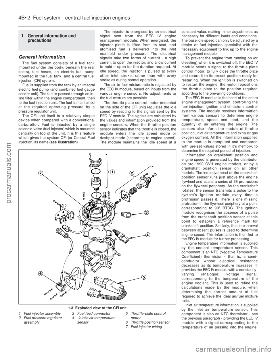
injection) its name (see illustration).The injector is energised by an electrical
signal sent from the EEC IV engine
management module. When energised, the
injector pintle is lifted from its seat, and
atomised fuel is delivered into the inlet
manifold under pressure. The electrical
signals take two forms of current - a high
current to open the injector, and a low current
to hold it open for the duration required. At
idle speed, the injector is pulsed at every
other inlet stroke, rather than with every
stroke as during normal operation.
The air-to-fuel mixture ratio is regulated by
the EEC IV module, based on inputs from the
various engine sensors. No adjustments to
the fuel mixture are possible.
The throttle plate control motor (mounted
on the side of the CFi unit) regulates the idle
speed by reacting to the signals sent by the
EEC IV module. The signals are calculated by
the values and information provided from the
engine sensors. When the throttle position
sensor indicates that the throttle is closed, the
module enters the idle speed mode or
dashpot mode (according to engine speed).
The module maintains the idle speed at a constant value, making minor adjustments as
necessary for different loads and conditions.
The base idle speed can only be adjusted by a
dealer or fuel injection specialist with the
necessary equipment to link up to the engine
management module.
To prevent the engine from running on (or
dieseling) when it is switched off, the EEC IV
module sends a signal to the throttle plate
control motor, to fully close the throttle plate
and return it to its preset position ready for
restarting. When the ignition is switched on
to restart the engine, the motor repositions
the throttle plate to the position required
according to the prevailing conditions. The EEC IV module is the heart of the entire
engine management system, controlling the
fuel injection, ignition and emissions control
systems. The module receives information
from various sensors to determine engine
temperature, speed and load, and the
quantity of air entering the engine. The
sensors also inform the module of throttle
position, inlet air temperature and exhaust gas
oxygen content. All the information supplied
to the module is computed and compared
with pre-set values stored in it’s memory, to
determine the required period of injection. Information on crankshaft position and
engine speed is generated by the distributor
on pre-1990 CVH engine models, or by a
crankshaft position sensor on all other
models. The inductive head of the crankshaft
position sensor runs just above the engine
flywheel and scans a series of 36 protrusions
on the flywheel periphery. As the crankshaft
rotates, the sensor transmits a pulse to the
system’s ignition module every time a
protrusion passes it. There is one missing
protrusion in the flywheel periphery at a point
corresponding to 90º BTDC. The ignition
module recognises the absence of a pulse
from the crankshaft position sensor at this
point to establish a reference mark for
crankshaft position. Similarly, the time interval
between absent pulses is used to determine
engine speed. This information is then fed to
the EEC IV module for further processing. Engine temperature information is supplied
by the coolant temperature sensor. This
component is an NTC (Negative Temperature
Coefficient) thermistor - that is, a semi-
conductor whose electrical resistance
decreases as its temperature increases. It
provides the EEC IV module with a constantly-
varying (analogue) voltage signal,
corresponding to the temperature of the
engine coolant. This is used to refine the
calculations made by the module, when
determining the correct amount of fuel
required to achieve the ideal air/fuel mixture
ratio. Inlet air temperature information is supplied
by the inlet air temperature sensor. This
component is also an NTC thermistor - see
the previous paragraph - providing the EEC IV
module with a signal corresponding to the
temperature of air passing into the engine.
4B•2 Fuel system - central fuel injection engines
1.3 Exploded view of the CFi unit
1 Fuel injector assembly
2 Fuel pressure regulator
assembly 3 Fuel feed connector
4 Intake air temperature
sensor 5 Throttle-plate control
motor
6 Throttle position sensor
7 Fuel injector wiring
1595Ford Fiesta Remakeprocarmanuals.com
http://vnx.su
Page 135 of 296
Torque wrench settingsNmlbf ft
Idle speed control valve bolts . . . . . . . . . . . . . . . . . . . . . . . . . . . . . . . . . 4 to 5 3 to 4
Fuel pressure regulator bolts . . . . . . . . . . . . . . . . . . . . . . . . . . . . . . . . . 8 to 12 6 to 9
Fuel rail bolts . . . . . . . . . . . . . . . . . . . . . . . . . . . . . . . . . . . .\
. . . . . . . . . 20 to 26 15 to 19
Inlet air temperature sensor . . . . . . . . . . . . . . . . . . . . . . . . . . . . . . . . . . 20 to 25 15 to 18
Inlet manifold . . . . . . . . . . . . . . . . . . . . . . . . . . . . . . . . . . . .\
. . . . . . . . . 16 to 20 12 to 15
Oxygen sensor . . . . . . . . . . . . . . . . . . . . . . . . . . . . . . . . . . . .\
. . . . . . . . 50 to 70 37 to 52
Intercooler-to-radiator bolts . . . . . . . . . . . . . . . . . . . . . . . . . . . . . . . . . . 4 to 6 3 to 5
Boost control valve screws . . . . . . . . . . . . . . . . . . . . . . . . . . . . . . . . . . . 2.2 to 2.7 1.5 to 2
Exhaust manifold heatshield bolts . . . . . . . . . . . . . . . . . . . . . . . . . . . . . 21 to 26 16 to 19
Exhaust manifold-to-engine nuts (non-Turbo models) . . . . . . . . . . . . . . 14 to 17 11 to 13
Exhaust manifold-to-engine nuts (Turbo models) . . . . . . . . . . . . . . . . . 28 to 31 21 to 23
Exhaust manifold-to-turbocharger bolts . . . . . . . . . . . . . . . . . . . . . . . . 20 to 28 15 to 21
Turbocharger-to-exhaust downpipe nuts . . . . . . . . . . . . . . . . . . . . . . . . 35 to 47 26 to 35
Turbocharger cooling pipe banjo union bolts . . . . . . . . . . . . . . . . . . . . . 22 to 29 17 to 22
Turbocharger oil feed and return line couplings . . . . . . . . . . . . . . . . . . . 15 to 20 11 to 15
4C•2 Fuel system - electronic fuel injection engines
1595Ford Fiesta Remake
1 General information and
precautions
General information
The fuel system consists of a fuel tank
(mounted under the body, beneath the rear
seats), fuel hoses, an electric fuel pump
mounted in the fuel tank, and an electronic
fuel injection system. Fuel is supplied under pressure from the
fuel pump to the fuel distributor rail mounted
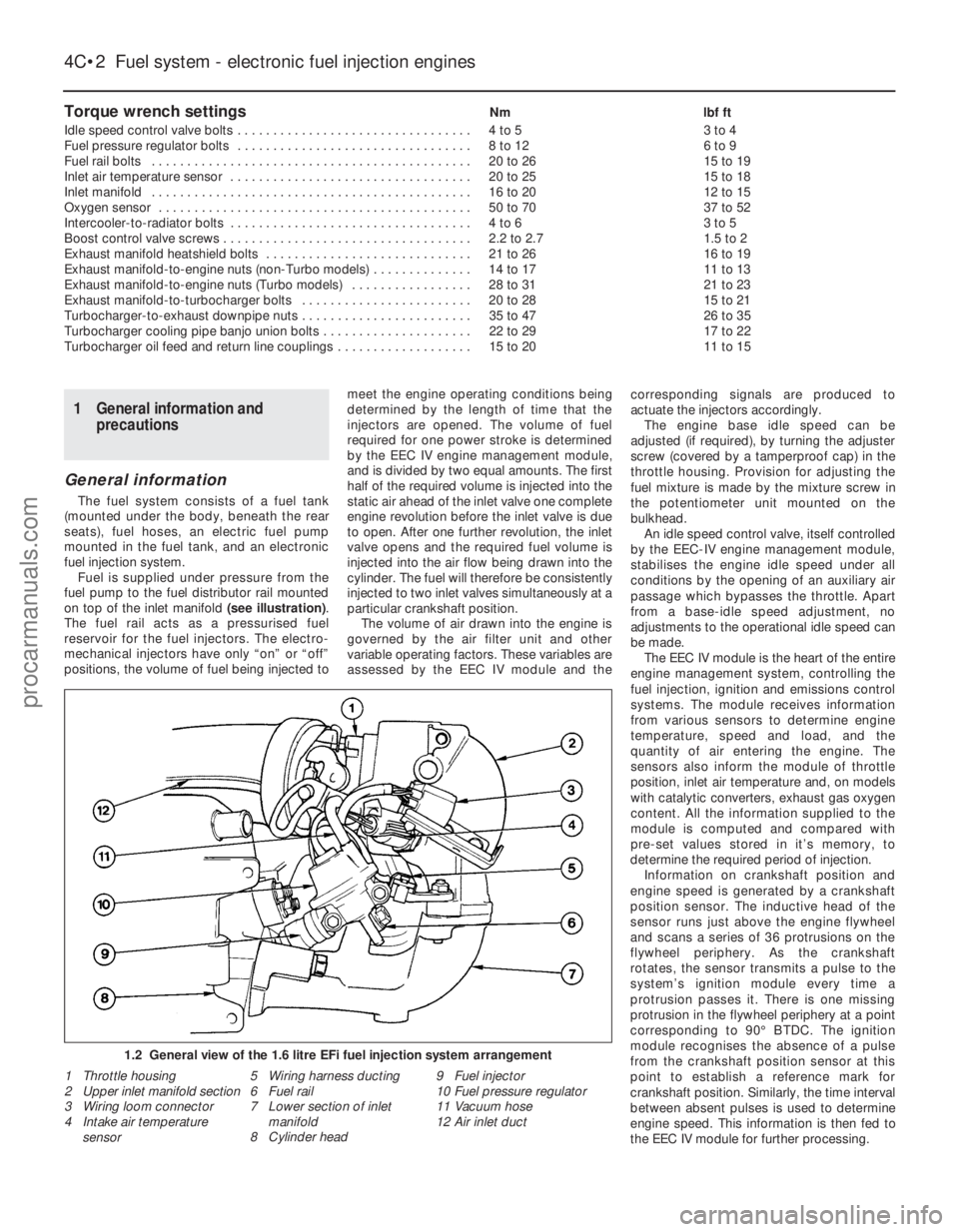
on top of the inlet manifold (see illustration).
The fuel rail acts as a pressurised fuel
reservoir for the fuel injectors. The electro-
mechanical injectors have only “on” or “off”
positions, the volume of fuel being injected to meet the engine operating conditions being
determined by the length of time that the
injectors are opened. The volume of fuel
required for one power stroke is determined
by the EEC IV engine management module,
and is divided by two equal amounts. The first
half of the required volume is injected into the
static air ahead of the inlet valve one complete
engine revolution before the inlet valve is due
to open. After one further revolution, the inlet
valve opens and the required fuel volume is
injected into the air flow being drawn into the
cylinder. The fuel will therefore be consistently
injected to two inlet valves simultaneously at a
particular crankshaft position.
The volume of air drawn into the engine is
governed by the air filter unit and other
variable operating factors. These variables are
assessed by the EEC IV module and the corresponding signals are produced to
actuate the injectors accordingly.
The engine base idle speed can be
adjusted (if required), by turning the adjuster
screw (covered by a tamperproof cap) in the
throttle housing. Provision for adjusting the
fuel mixture is made by the mixture screw in
the potentiometer unit mounted on the
bulkhead. An idle speed control valve, itself controlled
by the EEC-IV engine management module,
stabilises the engine idle speed under all
conditions by the opening of an auxiliary air
passage which bypasses the throttle. Apart
from a base-idle speed adjustment, no
adjustments to the operational idle speed can
be made. The EEC IV module is the heart of the entire
engine management system, controlling the
fuel injection, ignition and emissions control
systems. The module receives information
from various sensors to determine engine
temperature, speed and load, and the
quantity of air entering the engine. The
sensors also inform the module of throttle
position, inlet air temperature and, on models
with catalytic converters, exhaust gas oxygen
content. All the information supplied to the
module is computed and compared with
pre-set values stored in it’s memory, to
determine the required period of injection.
Information on crankshaft position and
engine speed is generated by a crankshaft
position sensor. The inductive head of the
sensor runs just above the engine flywheel
and scans a series of 36 protrusions on the
flywheel periphery. As the crankshaft
rotates, the sensor transmits a pulse to the
system’s ignition module every time a
protrusion passes it. There is one missing
protrusion in the flywheel periphery at a point
corresponding to 90° BTDC. The ignition
module recognises the absence of a pulse
from the crankshaft position sensor at this
point to establish a reference mark for
crankshaft position. Similarly, the time interval
between absent pulses is used to determine
engine speed. This information is then fed to
the EEC IV module for further processing.
1.2 General view of the 1.6 litre EFi fuel injection system arrangement\
1 Throttle housing
2 Upper inlet manifold section
3 Wiring loom connector
4 Intake air temperature sensor 5 Wiring harness ducting
6 Fuel rail
7 Lower section of inlet
manifold
8 Cylinder head 9 Fuel injector
10
Fuel pressure regulator
11 Vacuum hose
12 Air inlet duct
procarmanuals.com
http://vnx.su
Page 145 of 296
1 General information andprecautions
General information
The fuel system consists of a fuel tank
(mounted under the body, beneath the rear
seats), fuel hoses, an electric fuel pump
mounted in the fuel tank, and a sequential
electronic fuel injection system.
The electric fuel pump supplies fuel under
pressure to the fuel rail, which distributes fuel
evenly to all injectors. A pressure regulator
controls the system pressure in relation to
inlet tract depression. From the fuel rail, fuel is
injected into the inlet ports, just above the
inlet valves, by four fuel injectors. The system
also includes features such as the flushing of
fresh (ie, cold) fuel around each injector on
start-up, thus improving hot starts. The amount of fuel supplied by the injectors
is precisely controlled by the EEC IV engine
management module. The module uses the
signals derived from the crankshaft position
sensor and the camshaft position sensor, to
trigger each injector separately in cylinder
firing order (sequential injection), with benefits
in terms of better fuel economy and lower
exhaust emissions. The EEC IV module is the heart of the entire
engine management system, controlling the
fuel injection, ignition and emissions control
systems. The module receives information
from various sensors which is then computed
and compared with pre-set values stored in
it’s memory, to determine the required period
of injection. Information on crankshaft position and
engine speed is generated by a crankshaft
position sensor. The inductive head of the
sensor runs just above the engine flywheel
and scans a series of 36 protrusions on the
flywheel periphery. As the crankshaft rotates,
the sensor transmits a pulse to the system’s
ignition module every time a protrusion
passes it. There is one missing protrusion in
the flywheel periphery at a point
corresponding to 90° BTDC. The ignition
module recognises the absence of a pulse
from the crankshaft position sensor at this
point to establish a reference mark for
crankshaft position. Similarly, the time interval
between absent pulses is used to determine
engine speed. This information is then fed to
the EEC IV module for further processing. The camshaft position sensor is located in
the cylinder head so that it registers with a
lobe on the camshaft. The camshaft position
sensor functions in the same way as the
crankshaft position sensor, producing a series
of pulses; this gives the EEC IV module a
reference point, to enable it to determine the
firing order, and operate the injectors in the
appropriate sequence. The mass air flow sensor is based on a “hot-
wire” system, sending the EEC IV module a constantly-varying (analogue) voltage signal
corresponding to the mass of air passing into
the engine. Since air mass varies with
temperature (cold air being denser than warm),
measuring air mass provides the module with
a very accurate means of determining the
correct amount of fuel required to achieve the
ideal air/fuel mixture ratio.
Engine temperature information is supplied by
the coolant temperature sensor. This
component is an NTC (Negative Temperature
Coefficient) thermistor - that is, a semi-
conductor whose electrical resistance
decreases as its temperature increases. It
provides the EEC IV module with a constantly-
varying (analogue) voltage signal, corresponding
to the temperature of the engine coolant. This is
used to refine the calculations made by the
module, when determining the correct amount
of fuel required to achieve the ideal air/fuel
mixture ratio. Inlet air temperature information is supplied
by the inlet air temperature sensor. This
component is also an NTC thermistor - see
the previous paragraph - providing the
module with a signal corresponding to the
temperature of air passing into the engine.
This is used to refine the calculations made by
the module, when determining the correct
amount of fuel required to achieve the ideal
air/fuel mixture ratio. A throttle position sensor is mounted on the
end of the throttle valve spindle, to provide
the EEC IV module with a constantly-varying
(analogue) voltage signal corresponding to the
throttle opening. This allows the module to
register the driver’s input when determining
the amount of fuel required by the engine.
Road speed is monitored by the vehicle
speed sensor. This component is a Hall-effect
generator, mounted on the transmission’s
speedometer drive. It supplies the module
with a series of pulses corresponding to the
vehicle’s road speed, enabling the module to
control features such as the fuel shut-off on
overrun.
Where power steering is fitted, a pressure-
operated switch is screwed into the power
steering system’s high-pressure pipe. The
switch sends a signal to the EEC IV module to
reduce engine speed should the power
steering fluid pressure become excessively
high.
The oxygen sensor in the exhaust system
provides the module with constant feedback -
“closed-loop” control - which enables it to
adjust the mixture to provide the best possible
conditions for the catalytic converter to
operate. The air inlet side of the system consists of
an air cleaner housing, the mass air flow
sensor, an inlet hose and duct, and a throttle
housing. The throttle valve inside the throttle housing
is controlled by the driver, through the
accelerator pedal. As the valve opens, the
amount of air that can pass through the
system increases. As the throttle valve opens further, the mass air flow sensor signal alters,
and the EEC IV module opens each injector
for a longer duration, to increase the amount
of fuel delivered to the inlet ports.
Both the idle speed and mixture are under
the control of the EEC IV module, and cannot
be adjusted. Not only can they not be
adjusted, they cannot even be checked,
except with the use of special Ford diagnostic
equipment.
Precautions
Warning: Petrol is extremely
flammable - great care must be
taken when working on any part
of the fuel system. Do not
smoke or allow any naked flames or
uncovered light bulbs near the work area.
Note that gas powered domestic
appliances with pilot flames, such as
heaters, boilers and tumble dryers, also
present a fire hazard - bear this in mind if
you are working in an area where such
appliances are present. Always keep a
suitable fire extinguisher close to the work
area and familiarise yourself with its
operation before starting work. Wear eye
protection when working on fuel systems
and wash off any fuel spilt on bare skin
immediately with soap and water. Note
that fuel vapour is just as dangerous as
liquid fuel; a vessel that has just been
emptied of liquid fuel will still contain
vapour and can be potentially explosive.
Petrol is a highly dangerous and volatile
liquid, and the precautions necessary
when handling it cannot be overstressed. Many of the operations described in this
Chapter involve the disconnection of fuel
lines, which may cause an amount of fuel
spillage. Before commencing work, refer
to the above Warning and the information
in “Safety first” at the beginning of this
manual. When working with fuel system
components, pay particular attention to
cleanliness - dirt entering the fuel system
may cause blockages which will lead to
poor running.
Note: Residual pressure will remain in the fuel
lines long after the vehicle was last used,
when disconnecting any fuel line, it will be
necessary to depressurise the fuel system as
described in Section 2 .
2 Fuel system-
depressurisation
1
Refer to Part B, Section 2.
3 Fuel lines and fittings -
general information
Refer to Part B, Section 3.
4D•2 Fuel system - sequential electronic fuel injection engines
1595Ford Fiesta Remakeprocarmanuals.com
http://vnx.su