1989 FORD FIESTA tow
[x] Cancel search: towPage 5 of 296
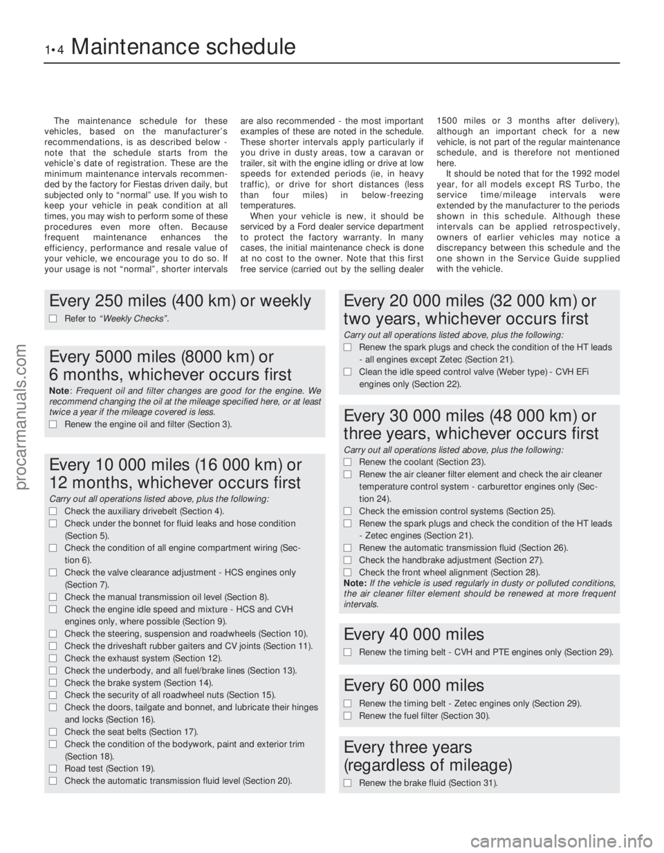
The maintenance schedule for these
vehicles, based on the manufacturer’s
recommendations, is as described below -
note that the schedule starts from the
vehicle’s date of registration. These are the
minimum maintenance intervals recommen-
ded by the factory for Fiestas driven daily, but
subjected only to “normal” use. If you wish to
keep your vehicle in peak condition at all
times, you may wish to perform some of these
procedures even more often. Because
frequent maintenance enhances the
efficiency, performance and resale value of
your vehicle, we encourage you to do so. If
your usage is not “normal”, shorter intervals are also recommended - the most important
examples of these are noted in the schedule.
These shorter intervals apply particularly if
you drive in dusty areas, tow a caravan or
trailer, sit with the engine idling or drive at low
speeds for extended periods (ie, in heavy
traffic), or drive for short distances (less
than four miles) in below-freezing
temperatures.
When your vehicle is new, it should be
serviced by a Ford dealer service department
to protect the factory warranty. In many
cases, the initial maintenance check is done
at no cost to the owner. Note that this first
free service (carried out by the selling dealer 1500 miles or 3 months after delivery),
although an important check for a new
vehicle, is not part of the regular maintenance
schedule, and is therefore not mentioned
here.
It should be noted that for the 1992 model
year, for all models except RS Turbo, the
service time/mileage intervals were
extended by the manufacturer to the periods
shown in this schedule. Although these
intervals can be applied retrospectively,
owners of earlier vehicles may notice a
discrepancy between this schedule and the
one shown in the Service Guide supplied
with the vehicle.
1•4Maintenance schedule
1595Ford Fiesta Remake
Every 250 miles (400 km) or weekly
m
m Refer to “Weekly Checks” .
Every 5000 miles (8000 km) or
6 months, whichever occurs first
Note: Frequent oil and filter changes are good for the engine. We
recommend changing the oil at the mileage specified here, or at least
twice a year if the mileage covered is less.
m m Renew the engine oil and filter (Section 3).
Every 10 000 miles (16 000 km) or
12 months, whichever occurs first
Carry out all operations listed above, plus the following:
m mCheck the auxiliary drivebelt (Section 4).
m
m Check under the bonnet for fluid leaks and hose condition
(Section 5).
m
m Check the condition of all engine compartment wiring (Sec-
tion 6).
m
m Check the valve clearance adjustment - HCS engines only
(Section 7).
m
m Check the manual transmission oil level (Section 8).
m
m Check the engine idle speed and mixture - HCS and CVH
engines only, where possible (Section 9).
m
m Check the steering, suspension and roadwheels (Section 10).
m
m Check the driveshaft rubber gaiters and CV joints (Section 11).
m
m Check the exhaust system (Section 12).
m
m Check the underbody, and all fuel/brake lines (Section 13).
m
m Check the brake system (Section 14).
m
m Check the security of all roadwheel nuts (Section 15).
m
m Check the doors, tailgate and bonnet, and lubricate their hinges
and locks (Section 16).
m
m Check the seat belts (Section 17).
m
m Check the condition of the bodywork, paint and exterior trim
(Section 18).
m
m Road test (Section 19).
m
m Check the automatic transmission fluid level (Section 20).
Every 20 000 miles (32 000 km) or
two years, whichever occurs first
Carry out all operations listed above, plus the following:
m mRenew the spark plugs and check the condition of the HT leads
- all engines except Zetec (Section 21).
m
m Clean the idle speed control valve (Weber type) - CVH EFi
engines only (Section 22).
Every 30 000 miles (48 000 km) or
three years, whichever occurs first
Carry out all operations listed above, plus the following:
m m Renew the coolant (Section 23).
m
m Renew the air cleaner filter element and check the air cleaner
temperature control system - carburettor engines only (Sec-
tion 24).
m m Check the emission control systems (Section 25).
m
m Renew the spark plugs and check the condition of the HT leads
- Zetec engines (Section 21).
m
m Renew the automatic transmission fluid (Section 26).
m
m Check the handbrake adjustment (Section 27).
m
m Check the front wheel alignment (Section 28).
Note: If the vehicle is used regularly in dusty or polluted conditions,
the air cleaner filter element should be renewed at more frequent
intervals.
Every 40 000 miles
m
m Renew the timing belt - CVH and PTE engines only (Section 29).
Every 60 000 miles
m
mRenew the timing belt - Zetec engines only (Section 29).
m
m Renew the fuel filter (Section 30).
Every three years
(regardless of mileage)
m m Renew the brake fluid (Section 31).
procarmanuals.com
http://vnx.su
Page 9 of 296
1•8Maintenance – component location
1595Ford Fiesta Remake
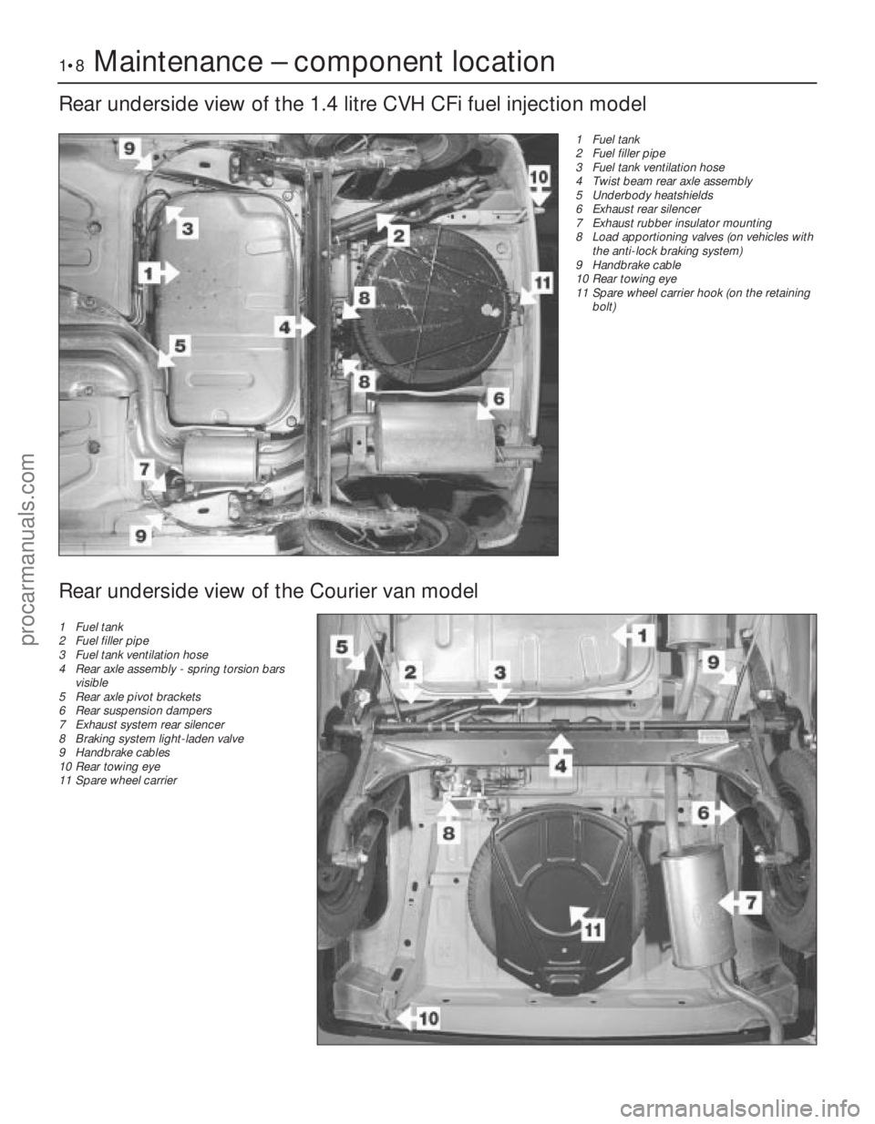
Rear underside view of the 1.4 litre CVH CFi fuel injection model
1 Fuel tank
2 Fuel filler pipe
3 Fuel tank ventilation hose
4 Twist beam rear axle assembly
5 Underbody heatshields
6 Exhaust rear silencer
7 Exhaust rubber insulator mounting
8 Load apportioning valves (on vehicles withthe anti-lock braking system)
9 Handbrake cable
10 Rear towing eye
11 Spare wheel carrier hook (on the retaining
bolt)
Rear underside view of the Courier van model
1 Fuel tank
2 Fuel filler pipe
3 Fuel tank ventilation hose
4 Rear axle assembly - spring torsion bars
visible
5 Rear axle pivot brackets
6 Rear suspension dampers
7 Exhaust system rear silencer
8 Braking system light-laden valve
9 Handbrake cables
10 Rear towing eye
11 Spare wheel carrier
procarmanuals.com
http://vnx.su
Page 27 of 296
up the fuel when the feed and outlet pipe
unions are disconnected.
4On models without quick-release couplings
on the fuel lines, slowly slacken the fuel feed
pipe union allowing the pressure in the fuel
pipe to reduce. When the pressure is fully
released, disconnect the fuel feed and outlet
pipe unions.
5 On models with quick-release couplings on
the fuel lines, release the fuel feed and outlet
pipe unions from the filter, by squeezing
together the protruding locking lugs on each
union, and carefully pulling the union off the
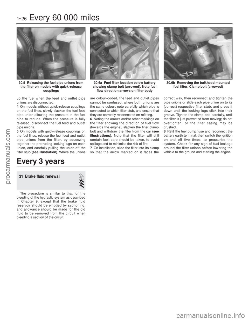
filter stub (see illustration) . Where the unions are colour-coded, the feed and outlet pipes
cannot be confused; where both unions are
the same colour, note carefully which pipe is
connected to which filter stub, and ensure that
they are correctly reconnected on refitting.
6
Noting the arrows and/or other markings on
the filter showing the direction of fuel flow
(towards the engine), slacken the filter clamp
bolt and withdraw the filter from the car (see
illustrations) . Note that the filter will still
contain fuel; care should be taken, to avoid
spillage and to minimise the risk of fire.
7 On installation, slide the filter into its clamp
so that the arrow marked on it faces the correct way, then reconnect and tighten the
pipe unions or slide each pipe union on to its
(correct) respective filter stub, and press it
down until the locking lugs click into their
groove. Tighten the clamp bolt carefully, until
the filter is just prevented from moving; do not
overtighten, or the filter casing may be
crushed.
8
Refit the fuel pump fuse and reconnect the
battery earth terminal, then switch the ignition
on and off five times, to pressurise the
system. Check for any sign of fuel leakage
around the filter unions before lowering the
vehicle to the ground and starting the engine.
1•26Every 60 000 miles
30.6b Removing the bulkhead mounted fuel filter. Clamp bolt (arrowed)30.6a Fuel filter location below battery
showing clamp bolt (arrowed). Note fuel flow direction arrows on filter body30.5 Releasing the fuel pipe unions fromthe filter on models with quick-release couplings
1595Ford Fiesta Remake
Every 3 years
31 Brake fluid renewal
3
The procedure is similar to that for the
bleeding of the hydraulic system as described
in Chapter 9, except that the brake fluid
reservoir should be emptied by syphoning,
and allowance should be made for the old
fluid to be removed from the circuit when
bleeding a section of the circuit.
procarmanuals.com
http://vnx.su
Page 45 of 296
of the crankshaft sprocket, and then pull the
belt vertically upright on its right-hand run.
Keep it taut, and engage it with the teeth of
the camshaft sprocket. If the original belt is
being refitted, check that the belt’s direction
of travel is correct, and realign the belt-to-
sprocket marks made during removal, to
ensure that the exact original engagement
positions are retained. When the belt is fully
fitted on the sprockets, check that the
sprocket positions have not altered.
9Carefully manoeuvre the belt around the
tensioner, and engage its teeth with the water
pump sprocket, again ensuring that the TDC
positions of the crankshaft and camshaft
are not disturbed as the belt is finally
located.
10 Refit the lower timing belt cover, and
tighten its retaining bolts to the specified
torque setting. Refit the crankshaft pulley, and
tighten its retaining bolt to the specified
torque setting.
11 To take up belt slack, loosen off the
tensioner and move it towards the front of the
car to apply an initial tension to the belt.
Secure the tensioner in this position, then
remove the flywheel ring gear locking device.
12 Rotate the crankshaft through two full
revolutions in (the normal direction of travel),
returning to the TDC position (camshaft
sprocket-to-cylinder head). Check that the
crankshaft pulley notch is aligned with the
TDC (0) mark on the lower half of the timing
belt cover.
13 Grasp the belt between the thumb and
forefinger, at the midway point between the
crankshaft and camshaft sprockets on the
right-hand side. If the belt tension is correct, it
should just be possible to twist the belt
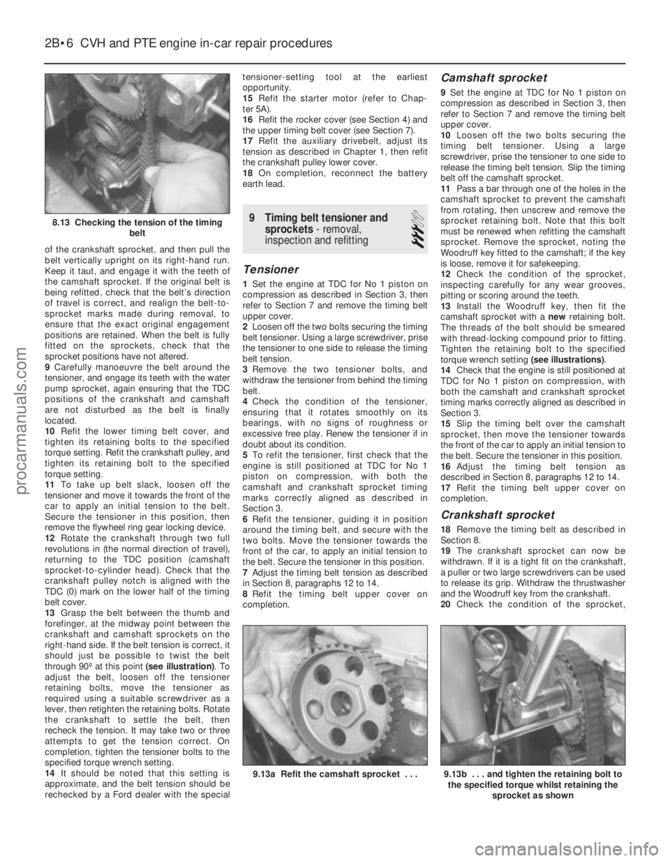
through 90º at this point (see illustration). To
adjust the belt, loosen off the tensioner
retaining bolts, move the tensioner as
required using a suitable screwdriver as a
lever, then retighten the retaining bolts. Rotate
the crankshaft to settle the belt, then
recheck the tension. It may take two or three
attempts to get the tension correct. On
completion, tighten the tensioner bolts to the
specified torque wrench setting.
14 It should be noted that this setting is
approximate, and the belt tension should be
rechecked by a Ford dealer with the special tensioner-setting tool at the earliest
opportunity.
15
Refit the starter motor (refer to Chap-
ter 5A).
16 Refit the rocker cover (see Section 4) and
the upper timing belt cover (see Section 7).
17 Refit the auxiliary drivebelt, adjust its
tension as described in Chapter 1, then refit
the crankshaft pulley lower cover.
18 On completion, reconnect the battery
earth lead.
9 Timing belt tensioner and sprockets - removal,
inspection and refitting
3
Tensioner
1 Set the engine at TDC for No 1 piston on
compression as described in Section 3, then
refer to Section 7 and remove the timing belt
upper cover.
2 Loosen off the two bolts securing the timing
belt tensioner. Using a large screwdriver, prise
the tensioner to one side to release the timing
belt tension.
3 Remove the two tensioner bolts, and
withdraw the tensioner from behind the timing
belt.
4 Check the condition of the tensioner,
ensuring that it rotates smoothly on its
bearings, with no signs of roughness or
excessive free play. Renew the tensioner if in
doubt about its condition.
5 To refit the tensioner, first check that the
engine is still positioned at TDC for No 1
piston on compression, with both the
camshaft and crankshaft sprocket timing
marks correctly aligned as described in
Section 3.
6 Refit the tensioner, guiding it in position
around the timing belt, and secure with the
two bolts. Move the tensioner towards the
front of the car, to apply an initial tension to
the belt. Secure the tensioner in this position.
7 Adjust the timing belt tension as described
in Section 8, paragraphs 12 to 14.
8 Refit the timing belt upper cover on
completion.
Camshaft sprocket
9 Set the engine at TDC for No 1 piston on
compression as described in Section 3, then
refer to Section 7 and remove the timing belt
upper cover.
10 Loosen off the two bolts securing the
timing belt tensioner. Using a large
screwdriver, prise the tensioner to one side to
release the timing belt tension. Slip the timing
belt off the camshaft sprocket.
11 Pass a bar through one of the holes in the
camshaft sprocket to prevent the camshaft
from rotating, then unscrew and remove the
sprocket retaining bolt. Note that this bolt
must be renewed when refitting the camshaft
sprocket. Remove the sprocket, noting the
Woodruff key fitted to the camshaft; if the key
is loose, remove it for safekeeping.
12 Check the condition of the sprocket,
inspecting carefully for any wear grooves,
pitting or scoring around the teeth.
13 Install the Woodruff key, then fit the
camshaft sprocket with a newretaining bolt.
The threads of the bolt should be smeared
with thread-locking compound prior to fitting.
Tighten the retaining bolt to the specified
torque wrench setting (see illustrations).
14 Check that the engine is still positioned at
TDC for No 1 piston on compression, with
both the camshaft and crankshaft sprocket
timing marks correctly aligned as described in
Section 3.
15 Slip the timing belt over the camshaft
sprocket, then move the tensioner towards
the front of the car to apply an initial tension to
the belt. Secure the tensioner in this position.
16 Adjust the timing belt tension as
described in Section 8, paragraphs 12 to 14.
17 Refit the timing belt upper cover on
completion.
Crankshaft sprocket
18 Remove the timing belt as described in
Section 8.
19 The crankshaft sprocket can now be
withdrawn. If it is a tight fit on the crankshaft,
a puller or two large screwdrivers can be used
to release its grip. Withdraw the thrustwasher
and the Woodruff key from the crankshaft.
20 Check the condition of the sprocket,
2B•6 CVH and PTE engine in-car repair procedures
9.13b . . . and tighten the retaining bolt to
the specified torque whilst retaining the
sprocket as shown9.13a Refit the camshaft sprocket . . .
8.13 Checking the tension of the timing belt
1595Ford Fiesta Remakeprocarmanuals.com
http://vnx.su
Page 63 of 296
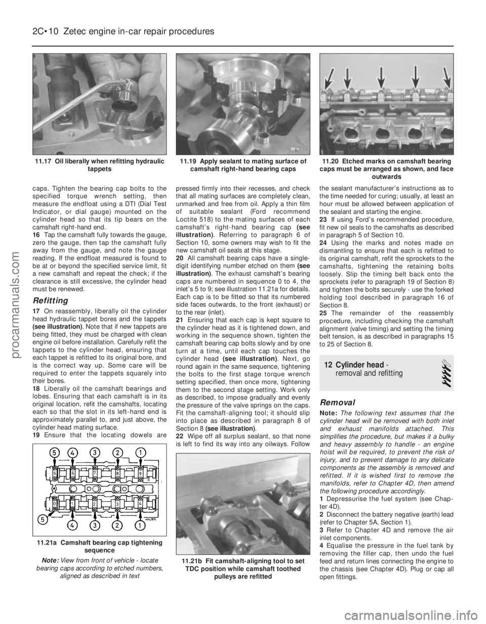
caps. Tighten the bearing cap bolts to the
specified torque wrench setting, then
measure the endfloat using a DTI (Dial Test
Indicator, or dial gauge) mounted on the
cylinder head so that its tip bears on the
camshaft right-hand end.
16Tap the camshaft fully towards the gauge,
zero the gauge, then tap the camshaft fully
away from the gauge, and note the gauge
reading. If the endfloat measured is found to
be at or beyond the specified service limit, fit
a new camshaft and repeat the check; if the
clearance is still excessive, the cylinder head
must be renewed.
Refitting
17 On reassembly, liberally oil the cylinder
head hydraulic tappet bores and the tappets
(see illustration) . Note that if new tappets are
being fitted, they must be charged with clean
engine oil before installation. Carefully refit the
tappets to the cylinder head, ensuring that
each tappet is refitted to its original bore, and
is the correct way up. Some care will be
required to enter the tappets squarely into
their bores.
18 Liberally oil the camshaft bearings and
lobes. Ensuring that each camshaft is in its
original location, refit the camshafts, locating
each so that the slot in its left-hand end is
approximately parallel to, and just above, the
cylinder head mating surface.
19 Ensure that the locating dowels are pressed firmly into their recesses, and check
that all mating surfaces are completely clean,
unmarked and free from oil. Apply a thin film
of suitable sealant (Ford recommend
Loctite 518) to the mating surfaces of each
camshaft’s right-hand bearing cap
(see
illustration) . Referring to paragraph 6 of
Section 10, some owners may wish to fit the
new camshaft oil seals at this stage.
20 All camshaft bearing caps have a single-
digit identifying number etched on them (see
illustration) . The exhaust camshaft’s bearing
caps are numbered in sequence 0 to 4, the
inlet’s 5 to 9; see illustration 11.21a for details.
Each cap is to be fitted so that its numbered
side faces outwards, to the front (exhaust) or
to the rear (inlet).
21 Ensuring that each cap is kept square to
the cylinder head as it is tightened down, and
working in the sequence shown, tighten the
camshaft bearing cap bolts slowly and by one
turn at a time, until each cap touches the
cylinder head (see illustration) . Next, go
round again in the same sequence, tightening
the bolts to the first stage torque wrench
setting specified, then once more, tightening
them to the second stage setting. Work only
as described, to impose gradually and evenly
the pressure of the valve springs on the caps.
Fit the camshaft-aligning tool; it should slip
into place as described in paragraph 8 of
Section 8 (see illustration) .
22 Wipe off all surplus sealant, so that none
is left to find its way into any oilways. Follow the sealant manufacturer’s instructions as to
the time needed for curing; usually, at least an
hour must be allowed between application of
the sealant and starting the engine.
23
If using Ford’s recommended procedure,
fit new oil seals to the camshafts as described
in paragraph 5 of Section 10.
24 Using the marks and notes made on
dismantling to ensure that each is refitted to
its original camshaft, refit the sprockets to the
camshafts, tightening the retaining bolts
loosely. Slip the timing belt back onto the
sprockets (refer to paragraph 19 of Section 8)
and tighten the bolts securely - use the forked
holding tool described in paragraph 16 of
Section 8.
25 The remainder of the reassembly
procedure, including checking the camshaft
alignment (valve timing) and setting the timing
belt tension, is as described in paragraphs 15
to 25 of Section 8.
12 Cylinder head -
removal and refitting
4
Removal
Note: The following text assumes that the
cylinder head will be removed with both inlet
and exhaust manifolds attached. This
simplifies the procedure, but makes it a bulky
and heavy assembly to handle - an engine
hoist will be required, to prevent the risk of
injury, and to prevent damage to any delicate
components as the assembly is removed and
refitted. If it is wished first to remove the
manifolds, refer to Chapter 4D, then amend
the following procedure accordingly.
1 Depressurise the fuel system (see Chap-
ter 4D).
2 Disconnect the battery negative (earth) lead
(refer to Chapter 5A, Section 1).
3 Refer to Chapter 4D and remove the air
inlet components.
4 Equalise the pressure in the fuel tank by
removing the filler cap, then undo the fuel
feed and return lines connecting the engine to
the chassis (see Chapter 4D). Plug or cap all
open fittings.
2C•10 Zetec engine in-car repair procedures
11.21b Fit camshaft-aligning tool to set TDC position while camshaft toothed
pulleys are refitted
11.21a Camshaft bearing cap tightening sequence
Note: View from front of vehicle - locate
bearing caps according to etched numbers, aligned as described in text
11.20 Etched marks on camshaft bearing
caps must be arranged as shown, and face outwards11.19 Apply sealant to mating surface ofcamshaft right-hand bearing caps11.17 Oil liberally when refitting hydraulic tappets
1595Ford Fiesta Remakeprocarmanuals.com
http://vnx.su
Page 76 of 296
3Referring to Chapter 1 for details, drain the
coolant and engine oil. Refit the drain plug to
the sump on completion.
4 Remove the bonnet as described in
Chapter 11.
5 Remove the air cleaner assembly as
described in the relevant Part of Chapter 4.
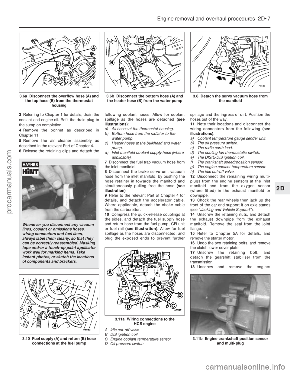
6 Release the retaining clips and detach the following coolant hoses. Allow for coolant
spillage as the hoses are detached
(see
illustrations) :
a) All hoses at the thermostat housing.
b) Bottom hose from the radiator to the
water pump.
c) Heater hoses at the bulkhead and water
pump.
d) Inlet manifold coolant supply hose (where
applicable).
7 Disconnect the fuel trap vacuum hose from
the inlet manifold.
8 Disconnect the brake servo unit vacuum
hose from the inlet manifold, by pushing the
hose retainer in towards the manifold and
simultaneously pulling free the hose (see
illustration) .
9 Refer to the relevant Part of Chapter 4 for
details, and detach the accelerator cable.
Where applicable, detach the choke cable
from the carburettor.
10 Compress the quick-release couplings at
the sides, and detach the fuel supply hose
and return hose from the fuel pump, CFi unit
or fuel rail (see illustration) . Allow for fuel
spillage as the hoses are disconnected, and
plug the exposed ends to prevent further spillage and the ingress of dirt. Position the
hoses out of the way.
11
Note their locations and disconnect the
wiring connectors from the following (see
illustrations) :
a) Coolant temperature gauge sender unit.
b) The oil pressure switch.
c) The radio earth lead.
d) The cooling fan thermostatic switch.
e) The DIS/E-DIS ignition coil.
f) The crankshaft speed/position sensor.
g) The engine coolant temperature sensor.
h) The idle cut-off valve.
12 Disconnect the remaining wiring multi-
plugs from the engine sensors at the inlet
manifold and from the oxygen sensor
(where fitted) in the exhaust manifold or
downpipe.
13 Chock the rear wheels then jack up the
front of the car and support it on axle stands
(see “Jacking and Vehicle Support” ).
14 Unscrew the retaining nuts, and detach
the exhaust downpipe from the exhaust
manifold. Remove the seal from the joint
flange.
15 Refer to Chapter 5A for details, and
remove the starter motor.
16 Undo the two retaining bolts, and remove
the clutch lower cover plate.
17 Unscrew the retaining bolt, and
detach the gearshift stabiliser from the
transmission.
18 Unscrew and remove the engine/
Engine removal and overhaul procedures 2D•7
3.8 Detach the servo vacuum hose from
the manifold3.6b Disconnect the bottom hose (A) andthe heater hose (B) from the water pump3.6a Disconnect the overflow hose (A) and the top hose (B) from the thermostat housing
3.11b Engine crankshaft position sensorand multi-plug
3.11a Wiring connections to the HCS engine
A Idle cut-off valve
B DIS ignition coil
C Engine coolant temperature sensor
D Oil pressure switch
3.10 Fuel supply (A) and return (B) hose connections at the fuel pump
2D
1595Ford Fiesta Remake
Whenever you disconnect any vacuum
lines, coolant or emissions hoses,
wiring connectors and fuel lines,
always label them clearly, so that they
can be correctly reassembled. Masking
tape and/or a touch-up paint applicator
work well for marking items. Take
instant photos, or sketch the locations
of components and brackets.
procarmanuals.com
http://vnx.su
Page 85 of 296
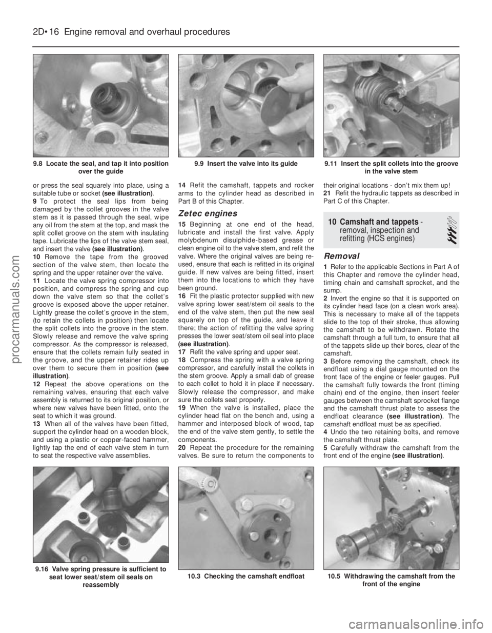
or press the seal squarely into place, using a
suitable tube or socket (see illustration).
9 To protect the seal lips from being
damaged by the collet grooves in the valve
stem as it is passed through the seal, wipe
any oil from the stem at the top, and mask the
split collet groove on the stem with insulating
tape. Lubricate the lips of the valve stem seal,
and insert the valve (see illustration).
10 Remove the tape from the grooved
section of the valve stem, then locate the
spring and the upper retainer over the valve.
11 Locate the valve spring compressor into
position, and compress the spring and cup
down the valve stem so that the collet’s
groove is exposed above the upper retainer.
Lightly grease the collet’s groove in the stem,
(to retain the collets in position) then locate
the split collets into the groove in the stem.
Slowly release and remove the valve spring
compressor. As the compressor is released,
ensure that the collets remain fully seated in
the groove, and the upper retainer rides up
over them to secure them in position (see
illustration) .
12 Repeat the above operations on the
remaining valves, ensuring that each valve
assembly is returned to its original position, or
where new valves have been fitted, onto the
seat to which it was ground.
13 When all of the valves have been fitted,
support the cylinder head on a wooden block,
and using a plastic or copper-faced hammer,
lightly tap the end of each valve stem in turn
to seat the respective valve assemblies. 14
Refit the camshaft, tappets and rocker
arms to the cylinder head as described in
Part B of this Chapter.
Zetec engines
15 Beginning at one end of the head,
lubricate and install the first valve. Apply
molybdenum disulphide-based grease or
clean engine oil to the valve stem, and refit the
valve. Where the original valves are being re-
used, ensure that each is refitted in its original
guide. If new valves are being fitted, insert
them into the locations to which they have
been ground.
16 Fit the plastic protector supplied with new
valve spring lower seat/stem oil seals to the
end of the valve stem, then put the new seal
squarely on top of the guide, and leave it
there; the action of refitting the valve spring
presses the lower seat/stem oil seal into place
(see illustration) .
17 Refit the valve spring and upper seat.
18 Compress the spring with a valve spring
compressor, and carefully install the collets in
the stem groove. Apply a small dab of grease
to each collet to hold it in place if necessary.
Slowly release the compressor, and make
sure the collets seat properly.
19 When the valve is installed, place the
cylinder head flat on the bench and, using a
hammer and interposed block of wood, tap
the end of the valve stem gently, to settle the
components.
20 Repeat the procedure for the remaining
valves. Be sure to return the components to their original locations - don’t mix them up!
21 Refit the hydraulic tappets as described in
Part C of this Chapter.10 Camshaft and tappets -
removal, inspection and
refitting (HCS engines)
3
Removal
1 Refer to the applicable Sections in Part A of
this Chapter and remove the cylinder head,
timing chain and camshaft sprocket, and the
sump.
2 Invert the engine so that it is supported on
its cylinder head face (on a clean work area).
This is necessary to make all of the tappets
slide to the top of their stroke, thus allowing
the camshaft to be withdrawn. Rotate the
camshaft through a full turn, to ensure that all
of the tappets slide up their bores, clear of the
camshaft.
3 Before removing the camshaft, check its
endfloat using a dial gauge mounted on the
front face of the engine or feeler gauges. Pull
the camshaft fully towards the front (timing
chain) end of the engine, then insert feeler
gauges between the camshaft sprocket flange
and the camshaft thrust plate to assess the
endfloat clearance (see illustration). The
camshaft endfloat must be as specified.
4 Undo the two retaining bolts, and remove
the camshaft thrust plate.
5 Carefully withdraw the camshaft from the
front end of the engine (see illustration).
2D•16 Engine removal and overhaul procedures
10.5 Withdrawing the camshaft from the
front of the engine10.3 Checking the camshaft endfloat9.16 Valve spring pressure is sufficient toseat lower seat/stem oil seals on
reassembly
9.11 Insert the split collets into the groove in the valve stem9.9 Insert the valve into its guide9.8 Locate the seal, and tap it into position over the guide
1595Ford Fiesta Remakeprocarmanuals.com
http://vnx.su
Page 86 of 296
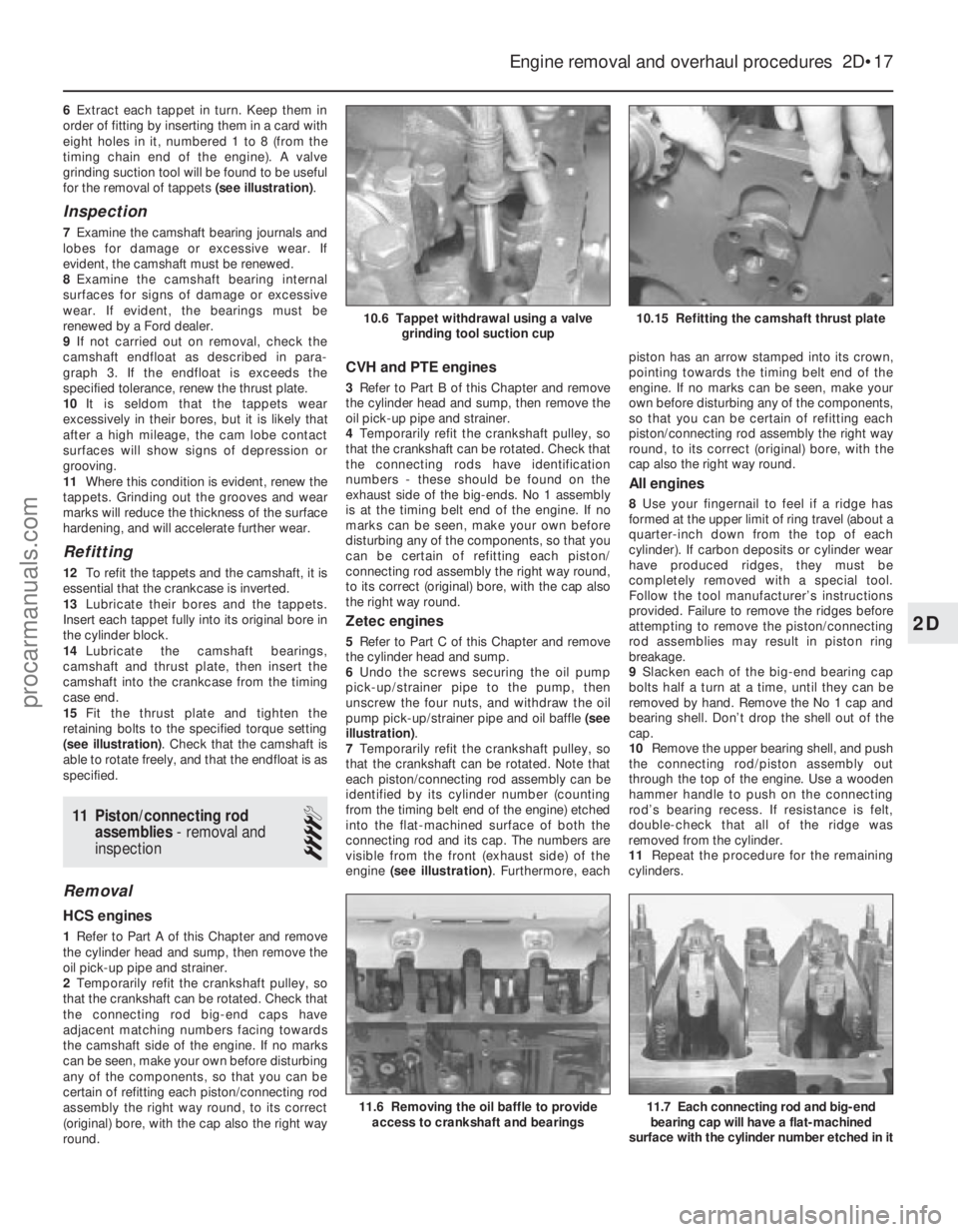
6Extract each tappet in turn. Keep them in
order of fitting by inserting them in a card with
eight holes in it, numbered 1 to 8 (from the
timing chain end of the engine). A valve
grinding suction tool will be found to be useful
for the removal of tappets (see illustration).
Inspection
7Examine the camshaft bearing journals and
lobes for damage or excessive wear. If
evident, the camshaft must be renewed.
8 Examine the camshaft bearing internal
surfaces for signs of damage or excessive
wear. If evident, the bearings must be
renewed by a Ford dealer.
9 If not carried out on removal, check the
camshaft endfloat as described in para-
graph 3. If the endfloat is exceeds the
specified tolerance, renew the thrust plate.
10 It is seldom that the tappets wear
excessively in their bores, but it is likely that
after a high mileage, the cam lobe contact
surfaces will show signs of depression or
grooving.
11 Where this condition is evident, renew the
tappets. Grinding out the grooves and wear
marks will reduce the thickness of the surface
hardening, and will accelerate further wear.
Refitting
12 To refit the tappets and the camshaft, it is
essential that the crankcase is inverted.
13 Lubricate their bores and the tappets.
Insert each tappet fully into its original bore in
the cylinder block.
14 Lubricate the camshaft bearings,
camshaft and thrust plate, then insert the
camshaft into the crankcase from the timing
case end.
15 Fit the thrust plate and tighten the
retaining bolts to the specified torque setting
(see illustration) . Check that the camshaft is
able to rotate freely, and that the endfloat is as
specified.
11 Piston/connecting rod
assemblies - removal and
inspection
4
Removal
HCS engines
1 Refer to Part A of this Chapter and remove
the cylinder head and sump, then remove the
oil pick-up pipe and strainer.
2 Temporarily refit the crankshaft pulley, so
that the crankshaft can be rotated. Check that
the connecting rod big-end caps have
adjacent matching numbers facing towards
the camshaft side of the engine. If no marks
can be seen, make your own before disturbing
any of the components, so that you can be
certain of refitting each piston/connecting rod
assembly the right way round, to its correct
(original) bore, with the cap also the right way
round.
CVH and PTE engines
3 Refer to Part B of this Chapter and remove
the cylinder head and sump, then remove the
oil pick-up pipe and strainer.
4 Temporarily refit the crankshaft pulley, so
that the crankshaft can be rotated. Check that
the connecting rods have identification
numbers - these should be found on the
exhaust side of the big-ends. No 1 assembly
is at the timing belt end of the engine. If no
marks can be seen, make your own before
disturbing any of the components, so that you
can be certain of refitting each piston/
connecting rod assembly the right way round,
to its correct (original) bore, with the cap also
the right way round.
Zetec engines
5 Refer to Part C of this Chapter and remove
the cylinder head and sump.
6 Undo the screws securing the oil pump
pick-up/strainer pipe to the pump, then
unscrew the four nuts, and withdraw the oil
pump pick-up/strainer pipe and oil baffle (see
illustration) .
7 Temporarily refit the crankshaft pulley, so
that the crankshaft can be rotated. Note that
each piston/connecting rod assembly can be
identified by its cylinder number (counting
from the timing belt end of the engine) etched
into the flat-machined surface of both the
connecting rod and its cap. The numbers are
visible from the front (exhaust side) of the
engine (see illustration) . Furthermore, each piston has an arrow stamped into its crown,
pointing towards the timing belt end of the
engine. If no marks can be seen, make your
own before disturbing any of the components,
so that you can be certain of refitting each
piston/connecting rod assembly the right way
round, to its correct (original) bore, with the
cap also the right way round.
All engines
8
Use your fingernail to feel if a ridge has
formed at the upper limit of ring travel (about a
quarter-inch down from the top of each
cylinder). If carbon deposits or cylinder wear
have produced ridges, they must be
completely removed with a special tool.
Follow the tool manufacturer’s instructions
provided. Failure to remove the ridges before
attempting to remove the piston/connecting
rod assemblies may result in piston ring
breakage.
9 Slacken each of the big-end bearing cap
bolts half a turn at a time, until they can be
removed by hand. Remove the No 1 cap and
bearing shell. Don’t drop the shell out of the
cap.
10 Remove the upper bearing shell, and push
the connecting rod/piston assembly out
through the top of the engine. Use a wooden
hammer handle to push on the connecting
rod’s bearing recess. If resistance is felt,
double- check that all of the ridge was
removed from the cylinder.
11 Repeat the procedure for the remaining
cylinders.
Engine removal and overhaul procedures 2D•17
10.15 Refitting the camshaft thrust plate10.6 Tappet withdrawal using a valve grinding tool suction cup
11.7 Each connecting rod and big-endbearing cap will have a flat-machined
surface with the cylinder number etched in it11.6 Removing the oil baffle to provide access to crankshaft and bearings
2D
1595Ford Fiesta Remakeprocarmanuals.com
http://vnx.su