Page 137 of 296

11On non-Turbo models, disconnect the
flexible hose between the air cleaner lid and
the air inlet duct.
12 On Turbo models, disconnect the idle
speed control valve air bypass hose from the
air inlet duct and the flexible hose between
the air inlet duct and intercooler (see
illustration) .
13 Undo the two retaining bolts, and remove
the air inlet duct from the rocker cover.
14 Refitting is the reverse of the removal
procedure.
5 Accelerator cable - removal,
refitting and adjustment
1
Removal
1 Disconnect the battery negative (earth) lead
(refer to Chapter 5A, Section 1).
2 Remove the air inlet components as
described in Section 4.
3 Fold back the carpet and insulation in the
driver’s footwell to gain access to the
accelerator pedal.
4 Detach the accelerator cable from the
pedal.
5 Working at the throttle housing end of the
cable, pivot the throttle quadrant by hand to
release the tension from the cable, then
detach the inner cable nipple from the throttle
lever (see illustration) .
6 Detach the outer cable from the
adjuster/support bracket, then remove the
cable.
Refitting and adjustment
7 Refit in the reverse order of removal. When
the cable is reconnected at each end, have an assistant depress the accelerator, and check
that the throttle fully opens and shuts without
binding. Ensure that there is a small amount of
slack in the inner cable when the throttle is
fully released. If adjustment is required,
release the outer cable retaining clip from the
cable at the adjustment/support bracket, slide
the cable through the adjuster grommet to the
point required, then refit the retaining clip to
secure it in the set position.
6 Accelerator pedal
-
removal and refitting
1
Refer to Part A, Section 5.
7 Fuel pump/fuel pressure -
checking
3
Note: Refer to the warning note in Section 1
before proceeding.
Fuel pump operation check
1 Switch on the ignition, and listen for the fuel
pump (the sound of an electric motor running,
audible from beneath the rear seats). Assuming
there is sufficient fuel in the tank, the pump
should start and run for approximately one or
two seconds, then stop, each time the ignition
is switched on. Note:If the pump runs
continuously all the time the ignition is switched
on, the electronic control system is running in
the backup (or “limp-home”) mode referred to
by Ford as “Limited Operation Strategy” (LOS).
This almost certainly indicates a fault in the
EEC IV module itself, and the vehicle should
therefore be taken to a Ford dealer for a full test of the complete system, using the correct
diagnostic equipment; do not waste time or risk
damaging the components by trying to test the
system without such facilities.
2
Listen for fuel return noises from the fuel
pressure regulator. It should be possible to
feel the fuel pulsing in the regulator and in the
feed hose from the fuel filter.
3 If the pump does not run at all, check the
fuse, relay and wiring (see Chapter 12). Check
also that the fuel cut-off switch has not been
activated and if so, reset it.
Fuel pressure check
4 A fuel pressure gauge will be required for
this check and should be connected in the
fuel line between the fuel filter and the fuel rail,
in accordance with the gauge maker’s
instructions.
5 Disconnect the wiring from the E-DIS
ignition coil and the fuel injectors.
6 Switch the ignition on and off twice, and
check that the pump pressure is as listed in
the Specifications .
7 If the pressure is not as specified, check the
fuel system for leaks or damage. If the system
appears okay, renew the fuel pump.
8 Reconnect the wiring to the ignition coil and
fuel injectors.
9 If the pump pressure was satisfactory, start
the engine and allow it to idle. Disconnect the
vacuum hose at the fuel pressure regulator,
and plug the hose. Note the gauge reading as
soon as the pressure stabilises, and compare
it with the figures given for regulated fuel
pressure in the Specifications.
10 If the regulated fuel pressure is not as
specified, remove the plug from the top of the
fuel pressure regulator, and using a suitable
Allen key, adjust the pressure regulator as
necessary.
11 Switch off the engine, and check that the
fuel pressure stays at the specified hold
pressure for two minutes after the engine is
turned off.
12 Carefully disconnect the fuel pressure
gauge, depressurising the system first as
described in Section 2. Reconnect the ignition
coil and fuel injector wiring.
13 Run the engine, and check that there are
no fuel leaks.
4C•4 Fuel system - electronic fuel injection engines
5.45 Accelerator cable retention
arrangement at the throttle linkage
4.12 Air intake, turbocharger and intercooler details on Turbo models
1595Ford Fiesta Remake
1 Fresh air intake
2 Air cleaner lid
3 Turbocharger
4 Intercooler
5 Air inlet duct
6 Throttle housing
7 Inlet manifold
8 (Hitachi-built) idle
speed control valveprocarmanuals.com
http://vnx.su
Page 138 of 296
, and")
8 Fuel tank- removal,
inspection and refitting
3
Proceed as described in Part A, Section 8,
but before disconnecting the battery, relieve
the residual pressure in the fuel system (see
Section 2), and equalise tank pressure by
removing the fuel filler cap.
9 Fuel pump/fuel gauge sender unit - removal and
refitting
3
Refer to Part B, Section 9.
10 Fuel tank ventilation tube -
removal and refitting
3
Refer to Part A, Section 10, but note that on
models with evaporative emission control, the
ventilation tube connects to the combined
roll-over/anti-trickle-fill valve assembly but,
instead of venting to atmosphere, a further
tube runs the length of the vehicle to a carbon
canister in the front right-hand corner of the
engine compartment.
Further information on the evaporative
emission control system is contained in Part E
of this Chapter.
11 Fuel tank filler pipe -
removal and refitting
3
Refer to Part A, Section 11.
12 Fuel cut-off switch -
removal and refitting
1
Refer to Part B, Section 12.
13 Fuel injection system -
checking
3
Refer to Part B, Section 13
14 Fuel injection system components - removal and
refitting
3
Note: Refer to the warning note in Section 1
before proceeding.
Fuel rail and injectors
Note: For simplicity, and to ensure that the
necessary absolute cleanliness on reassembly,
the following procedure describes the removal
of the fuel rail assembly, complete with the
injectors and pressure regulator, so that
the injectors can be serviced individually on a clean work surface. It is also possible to remove
and refit an individual injector, once the fuel
system has been depressurised and the battery
has been disconnected. If this approach is
followed, read through the complete
procedure, and work as described in the
relevant paragraphs, depending on the amount
of preliminary dismantling required. Be careful
not to allow any dirt to enter the system.
1
Relieve the residual pressure in the fuel
system (see Section 2), and equalise tank
pressure by removing the fuel filler cap. Warning: This procedure will
merely relieve the increased
pressure necessary for the engine
to run - remember that fuel will
still be present in the system components,
and take precautions accordingly before
disconnecting any of them.
2 Disconnect the battery negative (earth) lead
(refer to Chapter 5A, Section 1).
3 Disconnect the HT lead connectors from the
spark plugs, and release the leads from their
locating grooves in the air inlet duct. Position
them out of the way. On Turbo models, undo the
two screws and remove the HT lead bracket.
4 Remove the air inlet components as
described in Section 4.
5 Unscrew the retaining nuts and the bolt,
and detach the accelerator cable support
bracket at the throttle housing.
6 Disconnect the wiring connector from the
throttle position sensor.
7 Unscrew the four retaining bolts, and
remove the throttle housing and its mating
face gasket (see illustration) .
8 Disconnect the wiring multi-plug from the
engine coolant temperature sensor and the
inlet air temperature sensor.
9 Disconnect the wiring multi-plugs from the
fuel injectors, then undo the two retaining
bolts and detach the wiring harness from the
fuel rail (see illustrations) .
10 Unscrew the fuel supply pipe at the fuel
rail. Plug the rail and pipe, to prevent further
fuel spillage and the possible ingress of dirt.
11 Disconnect the fuel return and vacuum
pipes from the pressure regulator, and catch
any fuel spillage in a clean cloth.
12 Unscrew the fuel rail securing bolts, and
carefully withdraw the rail (complete with
injectors) from the engine (see illustrations).
Fuel system - electronic fuel injection engines 4C•5
14.9b . . . unbolt the wiring harness . . .
14.9a Disconnect the wiring multi-plug
from each injector . . .14.7 Throttle housing retaining boltlocations (arrowed)
4C
1595Ford Fiesta Remake 14.12a Remove the fuel rail retaining
bolts . . .
14.9c . . . and remove the completeharness
procarmanuals.com
http://vnx.su
Page 139 of 296
 . All seals must
be renewed (even if only one injector is to be
renewed).
14")
13Detach the fuel injectors from the fuel rail,
then remove the upper and lower seal from
each injector (see illustration) . All seals must
be renewed (even if only one injector is to be
renewed).
14 Prior to refitting the injectors, ensure that
all mating surfaces are perfectly clean.
Lubricate the new injector seals with clean
engine oil to ease their assembly to the
injectors.
15 Refitting is a reversal of the removal
procedure. Refer to the Specificationsat the
start of this Chapter for the tightening torques.
When refitting the fuel rail, ensure that the
injectors are correctly located. Ensure that the
mating surfaces of the throttle housing are
perfectly clean before assembling.
16 On completion, restart the engine and
check the various fuel connections for any
signs of leaks.
Fuel pressure regulator
17 Relieve the residual pressure in the fuel
system (see Section 2), and equalise tank
pressure by removing the fuel filler cap. Warning: This procedure will
merely relieve the increased
pressure necessary for the
engine to run - remember that
fuel will still be present in the system
components, and take precautions
accordingly before disconnecting any of
them.
18 Disconnect the battery negative (earth)
lead (refer to Chapter 5A, Section 1). 19
Release the fuel return pipe securing clip,
and detach the pipe from the regulator.
20 Pull free the vacuum pipe from the
regulator connector (see illustration).
21 Unscrew the two retaining bolts and
remove the regulator. Remove the old sealing
ring for renewal.
22 Refit in the reverse order of removal.
Lubricate the new seal ring with clean engine oil
to ease assembly. When the regulator is refitted
and the fuel and vacuum lines are reconnected,
turn the ignition on and off five times (without
cranking the engine) and check for any sign of
fuel leaks before restarting the engine.
Idle speed control valve
Note: The idle speed control valve may be
mounted on the air cleaner, on the engine
compartment bulkhead, or on the side of the
inlet manifold according to valve make and
year of manufacture. Valves manufactured by
Weber are mounted on the air cleaner and
require periodic maintenance (see Chapter 1).
Bulkhead and inlet manifold mounted valves
are manufactured by Hitachi and are
maintenance free.
23 Disconnect the battery negative (earth)
lead (refer to Chapter 5A, Section 1).
24 Disconnect the valve’s wiring multiplug
(see illustration) .
25 Where applicable disconnect the air
hose(s) from the valve.
26 Undo the two or four bolts (according to
type), and remove the valve from the air
cleaner, bulkhead or inlet manifold. 27
Refitting is a reversal of the removal
procedure. Ensure that the mating faces are
clean before reassembling.
28 When the valve is refitted, restart the
engine and check that there are no induction
leaks. Run the engine until its normal
operating temperature is reached, and check
that the idle speed is stable. Stop the engine,
connect up a tachometer in accordance with
its maker’s instructions, then restart the
engine and check that the idle speed is as
specified with all electrical items (lights, heater
blower motor, etc) switched off, then on. The
idle speed should remain the same. Switch off
the electrical items, turn the engine off and
detach the tachometer to complete the test.
Throttle housing
29 Disconnect the battery negative (earth)
lead (refer to Chapter 5A, Section 1).
30 Disconnect the ignition HT lead
connectors from the spark plugs, and release
the leads from their locating grooves in the air
inlet duct. Position them out of the way.
31 Remove the air inlet components as
described in Section 4.
32 Unscrew the retaining nuts and the bolt,
and detach the accelerator cable support
bracket at the throttle housing.
33 Disconnect the wiring connector from the
throttle position sensor.
34 Unscrew the four retaining bolts, and
remove the throttle housing and its mating
face gasket (see illustration 14.7) .
35 Refit in the reverse order of removal.
Check that the mating faces are clean, and fit
a new gasket.
EEC IV engine management
module
Note: The module is fragile. Take care not to
drop it, or subject it to any other kind of
impact. Do not subject it to extremes of
temperature, or allow it to get wet. Refer to
Part B, Section 14 for illustrations of the
following procedure.
36 Disconnect the battery negative (earth)
lead (refer to Chapter 5A, Section 1).
37 Unscrew and remove the two nuts
securing the module cover in the engine
compartment, then carefully draw the cover
away from its location. Unscrew the module
multi-plug retaining bolt and disconnect
the multi-plug from the module.
38 The aid of an assistant will be required at
this stage, to support and withdraw the
module from inside the passenger
compartment as its mounting bracket retaining
tags are compressed and released from the
engine compartment. Do not allow the module
to drop into the passenger compartment as
irreparable damage is likely to result. The
module may be separated from its mounting
bracket by undoing the securing bolts.
39 Refitting is a reversal of the removal
procedure, ensuring that the module
mounting bracket retaining tags are felt to
snap into position
4C•6 Fuel system - electronic fuel injection engines
14.24 Disconnect the multi-plug from the idle speed control valve. Upper valve
retaining bolt (arrowed)14.20 Fuel pressure regulator showingvacuum pipe (A) and fuel return pipe
connection (B)
14.13 Remove the seals from the injectors14.12b . . . and withdraw the fuel rail and injectors
1595Ford Fiesta Remakeprocarmanuals.com
http://vnx.su
Page 140 of 296

Crankshaft position sensor
40Refer to Chapter 5B.
Coolant temperature sensor
41Refer to Chapter 3.
Inlet air temperature sensor
42Remove the air inlet components as
described in Section 4.
43 Releasing its clip, unplug the sensor’s
electrical connector, then unscrew the sensor
from the inlet manifold (see illustration).
44 Refitting is the reverse of the removal
procedure.
Throttle position sensor
45 Remove the air inlet components as
described in Section 4.
46 Releasing its wire clip, unplug the
sensor’s electrical connector. Remove the
retaining screws, and withdraw the unit from
the throttle housing (see illustration). Do not
force the sensor’s centre to rotate past its
normal operating sweep; the unit will be
seriously damaged.
47 Refitting is the reverse of the removal
procedure, noting the following points (see
illustration) :
a) Ensure that the potentiometer is correctly
orientated, by locating its centre on the D-
shaped throttle shaft (throttle closed), and aligning the potentiometer body so that
the bolts pass easily into the throttle
housing.
b) Tighten the screws evenly and securely
(but do not overtighten them, or the
potentiometer body will be cracked).
Vehicle speed sensor
48 The sensor is mounted at the base of the
speedometer drive cable, and is removed with
the speedometer drive pinion. Refer to the
relevant Section of Chapter 7A or B, as
applicable.
Manifold absolute pressure
sensor
49 The sensor is located near the centre of
the engine compartment bulkhead.
50 Disconnect the wiring multi-plug, and
detach the vacuum hose from the base of the
sensor.
51 Undo the two retaining screws, and
withdraw the sensor from its location.
52 Refitting is the reverse of the removal
procedure.
Power steering pressure switch
53 Releasing its clip, unplug the switch’s
electrical connector, then unscrew the switch
from the power steering high pressure pipe.
Place a wad of rag underneath, to catch any spilt fluid. If a sealing washer is fitted, renew it
if it is worn or damaged.
54
Refitting is the reverse of the removal
procedure; tighten the switch securely, then
top-up the fluid reservoir (see “Weekly
Checks” ) to replace any fluid lost from the
system, and bleed out any trapped air (see
Chapter 10).
Oxygen sensor
Note: The sensor is delicate, and will not work
if it is dropped or knocked, if its power supply
is disrupted, or if any cleaning materials are
used on it.
55 Release the sensor’s wiring multi-plug
from its bracket below the starter motor, and
unplug it to disconnect the sensor.
56 Raise and support the front of the vehicle
if required to remove the sensor from
underneath (“see Jacking and vehicle
support” ). Remove the sensor heat shields
then unscrew the sensor from the exhaust
system front downpipe; collect the sealing
washer (where fitted).
57 On refitting, clean the sealing washer
(where fitted) and renew it if it is damaged or
worn. Apply a smear of anti-seize compound
to the sensor’s threads, to prevent them from
welding themselves to the downpipe in
service. Refit the sensor, tightening it to its
specified torque wrench setting; a slotted
socket will be required to do this. Reconnect
the wiring, and refit the connector plug.
Fuel mixture/CO% adjustment
potentiometer
58 The fuel mixture/CO% adjustment
potentiometer is located on the engine
compartment bulkhead below the ignition
module.
59 Disconnect the battery negative (earth)
lead (refer to Chapter 5A, Section 1).
60 Disconnect the potentiometer’s wiring
multiplug (see illustration) .
61 Unscrew the retaining screw and remove
the potentiometer from the bulkhead.
62 Refitting is the reverse of the removal
procedure.
Fuel system - electronic fuel injection engines 4C•7
14.46 Disconnect the multi-plug from the throttle position sensor. Sensor retaining screws (arrowed)14.43 Disconnecting the intake airtemperature sensor multi-plug
14.60 Fuel mixture/CO% adjustment potentiometer
A Securing screw B Multi-plug14.47 General view of the throttle position sensor and its “D” shaped throttle spindle location (arrowed)
4C
1595Ford Fiesta Remakeprocarmanuals.com
http://vnx.su
Page 141 of 296

15 Inlet manifold-
removal and refitting
4
Note: Refer to the warning note in Section 1
before proceeding.
Removal
1 The inlet manifold is a two-piece assembly
comprising an upper and lower section bolted
together (see illustration) .
2 Drain the cooling system with reference to
Chapter 1.
3 Depressurise the fuel system as described
in Section 2.
4 Disconnect the battery negative (earth) lead
(refer to Chapter 5A, Section 1).
5 Remove the air inlet components (Section
4) and disconnect the accelerator cable from
the throttle linkage (Section 5).
6 Remove the fuel injectors and fuel rail as
described in Section 14.
7 Noting their locations, disconnect the
coolant, vacuum and breather hoses from the
manifold.
8 Disconnect the wiring multi-plugs from the
engine sensors at the inlet manifold.
9 Undo the retaining bolts, and withdraw the
manifold from the cylinder head. Note the
location of the engine lifting bracket and earth
lead, where fitted. Remove the gasket.
10 With the manifold removed, clean all
traces of the old gasket from the mating surfaces of the manifold and the cylinder
head.
Refitting
11
Refitting is the reversal of removal. Use a
new gasket, and tighten the retaining bolts to
the specified torque (see illustration).
Refit the remainder of the components with
reference to the appropriate Chapters of this
manual. Refill the cooling system as
described in Chapter 1 on completion.
16 Turbocharger - general
information and precautions
General information
1 A water-cooled turbocharger is used on all
Turbo models covered by this manual. The
turbocharger increases the efficiency of the
engine by raising the pressure in the inlet
manifold above atmospheric pressure.
Instead of the air/fuel mixture being simply
sucked into the cylinders it is actively forced
in.
2 Energy for the operation of the
turbocharger comes from the exhaust gas.
The gas flows through a specially-shaped
housing (the turbine housing) and in so doing
spins the turbine wheel. The turbine wheel is
attached to a shaft, at the other end of which
is another vaned wheel known as the compressor wheel. The compressor wheel
spins in its own housing and compresses the
inducted air on the way to the inlet manifold.
3
After leaving the turbocharger, the
compressed air passes through an
intercooler, which is an air-to-air heat
exchanger mounted with the radiator. Here
the air gives up heat which it acquired when
being compressed. This temperature
reduction improves engine efficiency and
reduces the risk of detonation.
4 Boost pressure (the pressure in the inlet
manifold) is limited by the turbocharger
wastegate control, which diverts the exhaust
gas away from the turbine wheel in response
to the boost control valve. The valve is
controlled by the EEC IV engine management
module.
5 The turbo shaft is pressure-lubricated by
means of a feed pipe from the engine’s main oil
gallery. The shaft “floats” on a cushion of oil. A
drain pipe returns the oil to the sump.
6 Water cooling reduces the operating
temperature of the turbocharger, and in
particular, the shaft bearings. Water continues
to circulate by convection after the engine has
stopped, so cooling the unit if it is hot after a
long run.
Precautions
7 The turbocharger operates at extremely
high speeds and temperatures. Certain
precautions must be observed to avoid
premature failure of the turbo or injury to the
operator. a) Do not operate the turbo with any parts
exposed. Foreign objects falling onto the
rotating vanes could cause extensive
damage and (if ejected) personal injury.
b) Do not race the engine immediately after
start-up, especially if it is cold. Give the oil
a few seconds to circulate.
c) Always allow the engine to return to idle
speed before switching it off - do not blip
the throttle and switch off, as this will
leave the turbo spinning without
lubrication.
d) Allow the engine to idle for several
minutes before switching off after a high-
speed run.
e) Observe the recommended intervals for oil and filter changing, and use a
reputable oil of the specified quality.
Neglect of oil changing, or use of inferior
oil, can cause carbon formation on the
turbo shaft and subsequent failure.
17 Intercooler -
removal and refitting
2
Removal
1 Disconnect the battery negative (earth) lead
(refer to Chapter 5A, Section 1).
2 Remove the flexible hose connecting the
intercooler to the air inlet duct, then the pipe
4C•8 Fuel system - electronic fuel injection engines
15.1 Exploded view of the inlet manifold arrangement
1595Ford Fiesta Remakeprocarmanuals.com
http://vnx.su
Page 142 of 296
 . Use
adhesive tape to seal the turbocharger ports
against the entry of dirt.
3 Unbolt the horn nearest the int")
and flexible hose connecting the turbocharger
to the intercooler (see illustration 4.12) . Use
adhesive tape to seal the turbocharger ports
against the entry of dirt.
3 Unbolt the horn nearest the intercooler.
4 Unbolt the radiator/intercooler assembly
from the bonnet closure panel and the body
crossmember.
5 Move the assembly as far as possible
towards the engine, and unbolt the intercooler
from the radiator; withdraw the intercooler.
Refitting
6 Refitting is the reverse of the removal
procedure, tightening all nuts and bolts to the
specified torque settings, and not forgetting
to unseal the turbocharger openings before
reconnecting the intercooler pipe and hose.
18 Turbocharger boost control valve - removal and refitting
2
Removal
1Disconnect the battery negative (earth) lead
(refer to Chapter 5A, Section 1).
2 Disconnect the control valve wiring at its
multi-plug (see illustration) .
3 Marking or labelling the valve hoses so that
each can be reconnected to its original union,
disconnect the hoses from the valve.
4 Remove the securing screws and withdraw
the valve.
Refitting
5 Refitting is the reverse of the removal
procedure; tighten the screws to the specified
torque setting.
19 Turbocharger boost pressure - checking and
adjustment
5
Accurate checking and adjustment of the
turbocharger boost pressure requires considerable skill and experience and the use
of Ford special tools and diagnostic test
equipment. This work should therefore be
entrusted to a Ford dealer or performance
engine specialist.
20 Turbocharger
- removal,
examination and refitting
3
Removal
1 Disconnect the battery negative (earth) lead
(refer to Chapter 5A, Section 1).
2 Drain the cooling system as described in
Chapter 1.
3 Remove the air inlet components as
described in Section 4.
4 Disconnect the turbocharger coolant feed
and return hoses by slackening the clamps
and pulling the hoses off the turbocharger’s
metal pipes (see illustration) .
5 Remove the pipe and flexible hoses
connecting the turbocharger to the air cleaner
and intercooler. Use adhesive tape to seal the
turbocharger ports against the entry of dirt.
6 Disconnect the turbocharger oil feed and
return pipes by unscrewing the couplings.
7 Remove its three retaining screws and
withdraw the exhaust manifold heat shield.
8 Disconnect the exhaust system downpipe
from the turbocharger, then disconnect the
hose from the boost control valve to the
turbocharger wastegate control actuator.
9 Unscrew the exhaust manifold nuts, and
withdraw the manifold and turbocharger as an
assembly, protecting the radiator with
cardboard or similar.
10 To separate the turbocharger from the
manifold, flatten back the raised lockwasher tabs and unscrew the three retaining bolts.
Disconnect the turbocharger oil and coolant
pipes if required. This is as far as the unit can
be dismantled;
do notdisturb the wastegate
or its actuator and linkage.
Examination
11 With the turbocharger in the vehicle,
check that there are no air leaks around any
part of the air inlet components, and that the
boost control valve hoses are intact and
securely fastened.
12 With the turbocharger removed, check the
turbine wheels and blades (as far as possible)
for signs of wear or damage. Spin the turbine
and check that it rotates smoothly and easily,
with no sign of roughness, free play or
abnormal noise. If possible, check for axial
play (endfloat) of the shaft. Check that the
wastegate, its actuator and linkage show no
visible signs of wear, damage or stiffness due
to dirt and corrosion.
13 If any sign of wear or damage is found,
the turbocharger must be renewed.
Refitting
14 Refitting is the reverse of the removal
procedure, noting the following points: a) Refit the oil and coolant pipes, tightening
the unions to the specified torque
settings.
b) Always use new lockwashers when
refitting the turbocharger to the manifold;
again, tighten the bolts to their specified
torque setting.
c) Protect the radiator when refitting the
assembly, and always fit a new exhaust
manifold gasket.
d) Ensure that the oil feed and return pipes
are absolutely clean before reconnecting
them and tightening them to the specified
torque setting.
e) Owners are well advised to change the engine oil and filter whenever the
turbocharger is disturbed (see Chap-
ter 1).
f) When reassembly is complete and the
cooling system refilled (see Chapter 1),
disable the ignition system by
disconnecting the E-DIS ignition coil
wiring multi-plug, then turn the engine
over on the starter motor until the oil
pressure light goes out. This is essential
to ensure that the turbocharger oil supply
is established BEFORE the engine is
started; do not forget to reconnect
the coil before attempting to start the
engine
Fuel system - electronic fuel injection engines 4C•9
20.4 Turbocharger/exhaust manifold assembly details
A Exhaust manifold-to-turbocharger bolts
B Oil pipes
C Coolant pipes (metal)
4C
1595Ford Fiesta Remake
18.2 Location of turbo boost control valve (arrowed)
procarmanuals.com
http://vnx.su
Page 143 of 296
4C•10 Fuel system - electronic fuel injection engines
1595Ford Fiesta Remake
Notes
procarmanuals.com
http://vnx.su
Page 144 of 296

Application .")
4D
1595Ford Fiesta Remake
General
System type . . . . . . . . . . . . . . . . . . . . . . . . . . . . . . . . . . . .\
. . . . . . . . . . Sequential Electronic Fuel injection (SEFi)
Application . . . . . . . . . . . . . . . . . . . . . . . . . . . . . . . . . . . .\
. . . . . . . . . . . 1.4 litre PTE engines and 1.6 and 1.8 litre Zetec engines
Fuel grade
Fuel octane requirement . . . . . . . . . . . . . . . . . . . . . . . . . . . . . . . . . . . .\
. 95 RON unleaded
Fuel pressure
Regulated fuel pressure:*Pressure regulator vacuum hose disconnected . . . . . . . . . . . . . . . . . 2.7 ± 0.2 bars
With engine running and pressure regulator vacuum hose connected . . . . . . . . . . . . . . . . . . . . . . . . . . . . . . . . . . . .\
. . . . . . . . 2.1 ± 0.2 bars
Hold pressure - engine stopped after five minutes* . . . . . . . . . . . . . . . . 1.8 bars minimum
*The figures quoted are specific to Zetec engines. No values are quoted \
by the manufacturer for PTE engines, however they are likely to be similar.
Torque wrench settingsNm lbf ft
PTE engines
Inlet air duct to cylinder head cover . . . . . . . . . . . . . . . . . . . . . . . . . . . . 9 7
Inlet manifold to cylinder head . . . . . . . . . . . . . . . . . . . . . . . . . . . . . . . . 18 13
Inlet manifold upper to lower sections . . . . . . . . . . . . . . . . . . . . . . . . . . 18 13
Inlet air temperature sensor . . . . . . . . . . . . . . . . . . . . . . . . . . . . . . . . . . 15 11
Fuel rail-to-lower inlet manifold . . . . . . . . . . . . . . . . . . . . . . . . . . . . . . . 23 17
Camshaft position sensor . . . . . . . . . . . . . . . . . . . . . . . . . . . . . . . . . . . .\
6 4
Oxygen sensor . . . . . . . . . . . . . . . . . . . . . . . . . . . . . . . . . . . .\
. . . . . . . . 60 44
Zetec engines
Throttle housing-to-inlet manifold screws . . . . . . . . . . . . . . . . . . . . . . . 9 7
Inlet manifold to cylinder head . . . . . . . . . . . . . . . . . . . . . . . . . . . . . . . . 18 13
Idle speed control valve bolts . . . . . . . . . . . . . . . . . . . . . . . . . . . . . . . . . 6 4
Inlet air temperature sensor . . . . . . . . . . . . . . . . . . . . . . . . . . . . . . . . . . 15 11
Fuel pressure regulator bolts . . . . . . . . . . . . . . . . . . . . . . . . . . . . . . . . . 6 4
Fuel injector bolts . . . . . . . . . . . . . . . . . . . . . . . . . . . . . . . . . . . .\
. . . . . . 6 4
Fuel rail-to-inlet manifold bolts . . . . . . . . . . . . . . . . . . . . . . . . . . . . . . . . 9 7
Camshaft position sensor . . . . . . . . . . . . . . . . . . . . . . . . . . . . . . . . . . . .\
8 6
Oxygen sensor . . . . . . . . . . . . . . . . . . . . . . . . . . . . . . . . . . . .\
. . . . . . . . 60 44
Chapter 4 Part D: Fuel system -
sequential electronic fuel injection engines
Accelerator cable - removal, refitting and adjustment . . . . . . . . . . . 5
Accelerator pedal - removal and refitting . . . . . . . . . . . . . . . . . . . . . 6
Air cleaner assembly and air inlet components - removal and
refitting . . . . . . . . . . . . . . . . . . . . . . . . . . . . . . . . . . . .\
. . . . . . . . . . 4
Air cleaner element renewal . . . . . . . . . . . . . . . . . . . . . .See Chapter 1
Fuel cut-off switch - removal and refitting . . . . . . . . . . . . . . . . . . . . 12
Fuel filter renewal . . . . . . . . . . . . . . . . . . . . . . . . . . \
. . . . .See Chapter 1
Fuel injection system - checking . . . . . . . . . . . . . . . . . . . . . . . . . . . . 13
Fuel injection system components - removal and refitting . . . . . . . . 14
Fuel lines and fittings - general information . . . . . . . . . . . . . . . . . . . 3
Fuel pump/fuel gauge sender unit - removal and refitting . . . . . . . . 9 Fuel pump/fuel pressure - checking . . . . . . . . . . . . . . . . . . . . . . . . . 7
Fuel system - depressurisation . . . . . . . . . . . . . . . . . . . . . . . . . . . . . 2
Fuel tank - removal, inspection and refitting . . . . . . . . . . . . . . . . . . . 8
Fuel tank filler pipe - removal and refitting . . . . . . . . . . . . . . . . . . . . 11
Fuel tank ventilation tube - removal and refitting . . . . . . . . . . . . . . . 10
General fuel system checks . . . . . . . . . . . . . . . . . . . . . .See Chapter 1
General information and precautions . . . . . . . . . . . . . . . . . . . . . . . . 1
Inlet manifold - removal and refitting . . . . . . . . . . . . . . . . . . . . . . . . 15
Underbody fuel/brake line check . . . . . . . . . . . . . . . . . . .See\
Chapter 1
Underbonnet check for fluid leaks and hose condition . .See Chapter 1
4D•1
Specifications Contents
Easy,
suitable for
novice with little
experience Fairly easy,
suitable
for beginner with
some experience Fairly difficult,
suitable for competent
DIY mechanic
Difficult,
suitable for
experienced DIY
mechanic Very difficult,
suitable for expert DIY
or professional
Degrees of difficulty
54321
procarmanuals.com
http://vnx.su
 1
1 2
2 3
3 4
4 5
5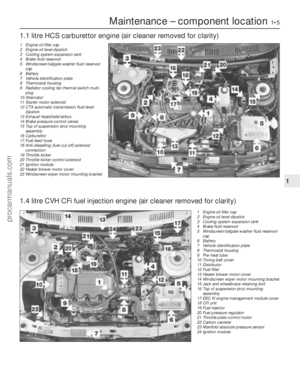 6
6 7
7 8
8 9
9 10
10 11
11 12
12 13
13 14
14 15
15 16
16 17
17 18
18 19
19 20
20 21
21 22
22 23
23 24
24 25
25 26
26 27
27 28
28 29
29 30
30 31
31 32
32 33
33 34
34 35
35 36
36 37
37 38
38 39
39 40
40 41
41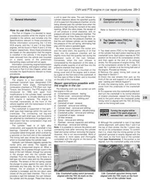 42
42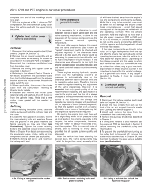 43
43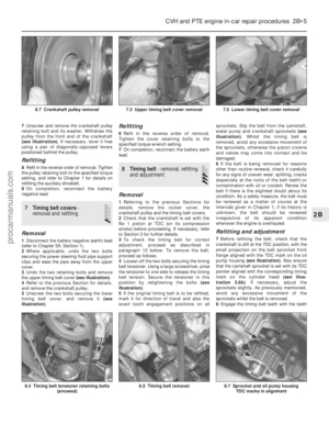 44
44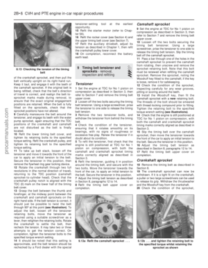 45
45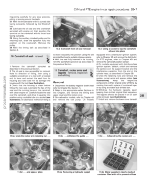 46
46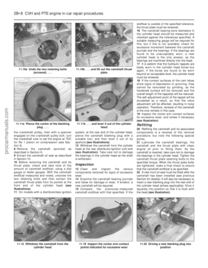 47
47 48
48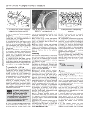 49
49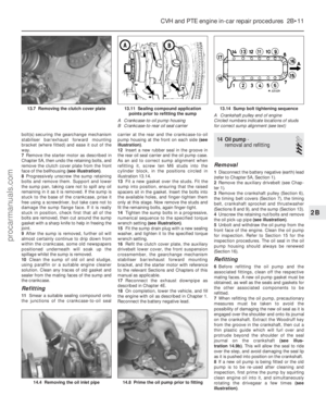 50
50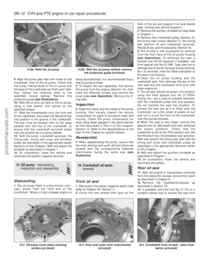 51
51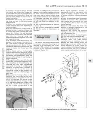 52
52 53
53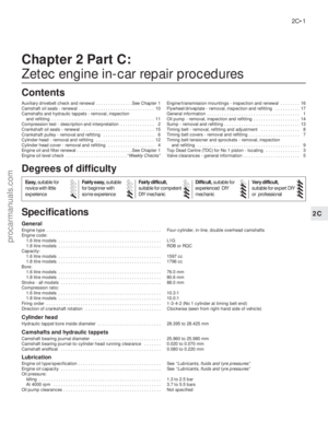 54
54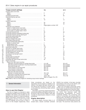 55
55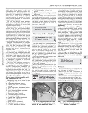 56
56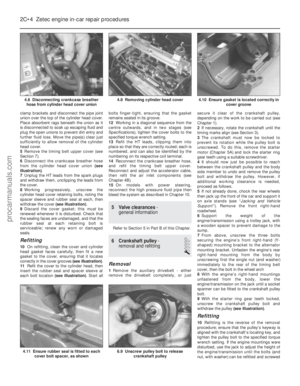 57
57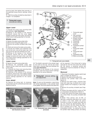 58
58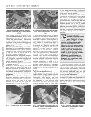 59
59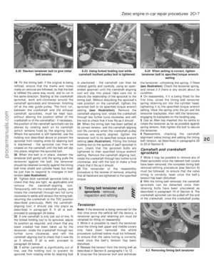 60
60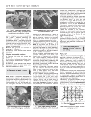 61
61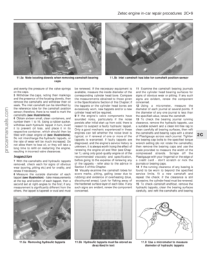 62
62 63
63 64
64 65
65 66
66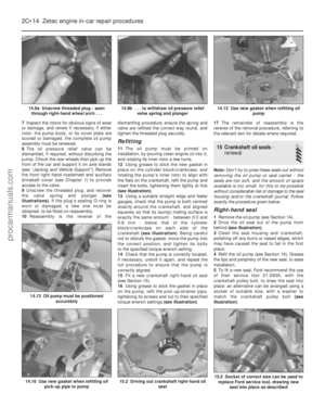 67
67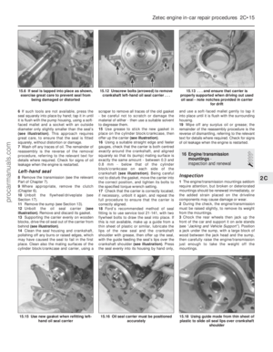 68
68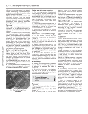 69
69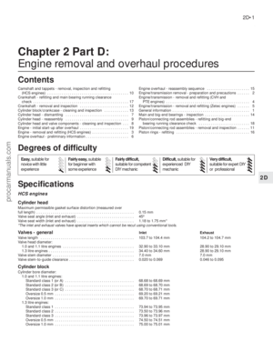 70
70 71
71 72
72 73
73 74
74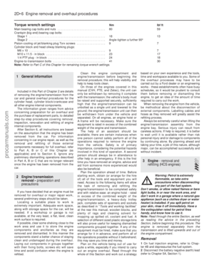 75
75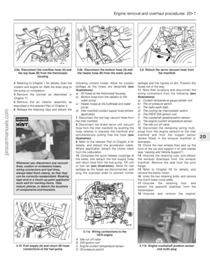 76
76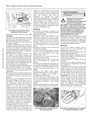 77
77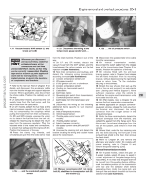 78
78 79
79 80
80 81
81 82
82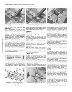 83
83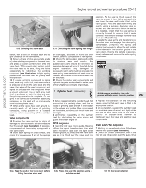 84
84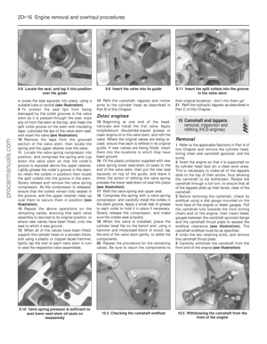 85
85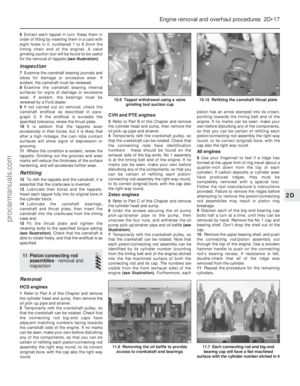 86
86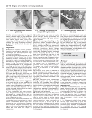 87
87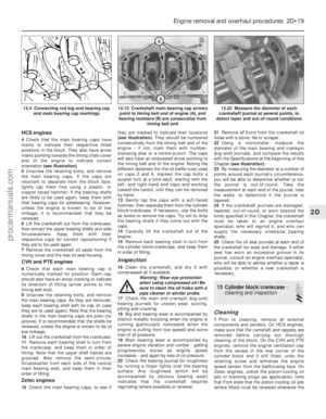 88
88 89
89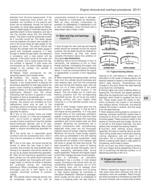 90
90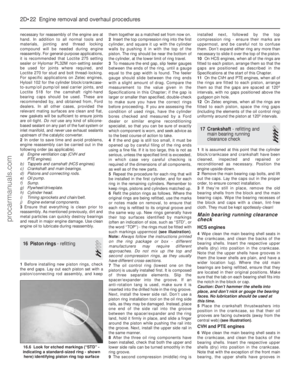 91
91 92
92 93
93 94
94 95
95 96
96 97
97 98
98 99
99 100
100 101
101 102
102 103
103 104
104 105
105 106
106 107
107 108
108 109
109 110
110 111
111 112
112 113
113 114
114 115
115 116
116 117
117 118
118 119
119 120
120 121
121 122
122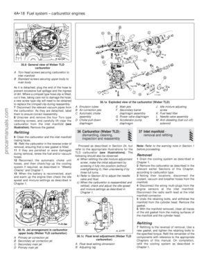 123
123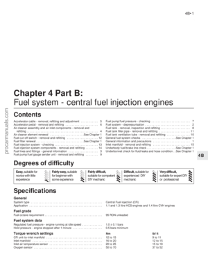 124
124 125
125 126
126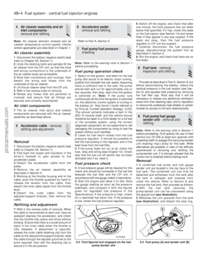 127
127 128
128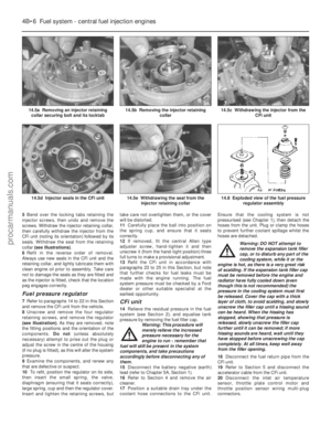 129
129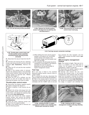 130
130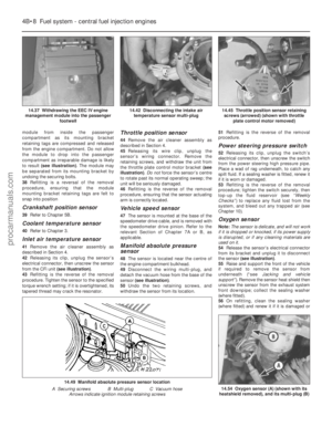 131
131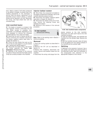 132
132 133
133 134
134 135
135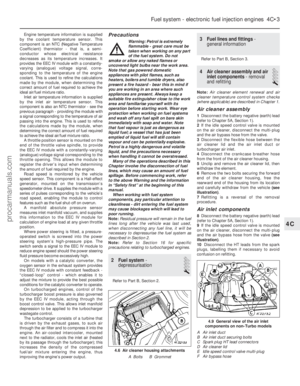 136
136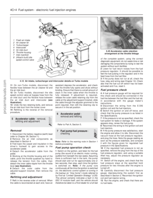 137
137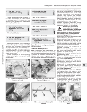 138
138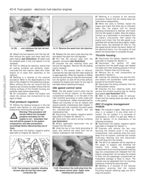 139
139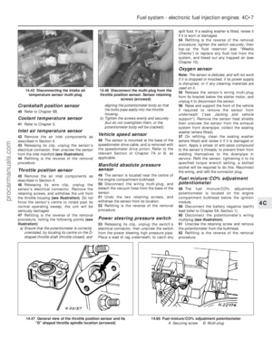 140
140 141
141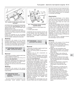 142
142 143
143 144
144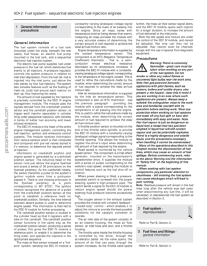 145
145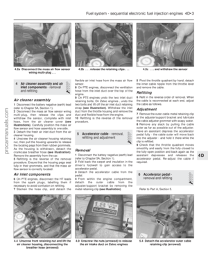 146
146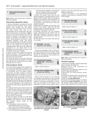 147
147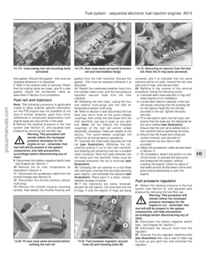 148
148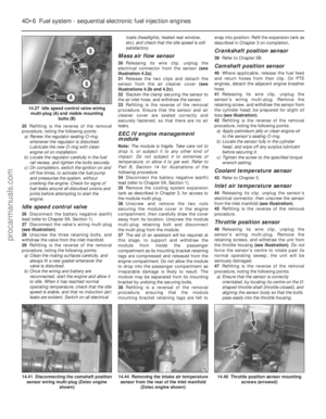 149
149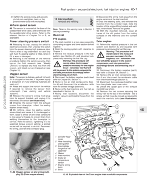 150
150 151
151 152
152 153
153 154
154 155
155 156
156 157
157 158
158 159
159 160
160 161
161 162
162 163
163 164
164 165
165 166
166 167
167 168
168 169
169 170
170 171
171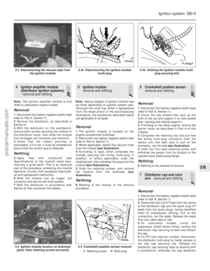 172
172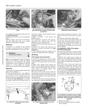 173
173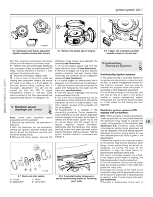 174
174 175
175 176
176 177
177 178
178 179
179 180
180 181
181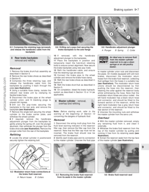 182
182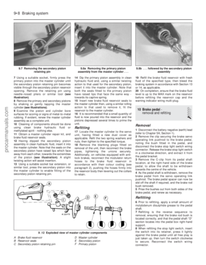 183
183 184
184 185
185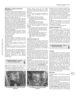 186
186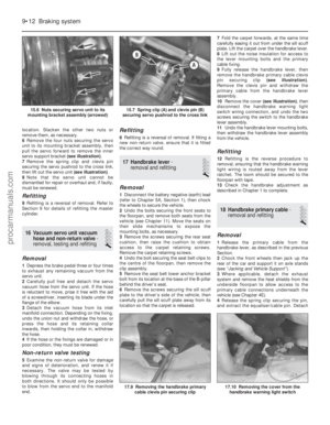 187
187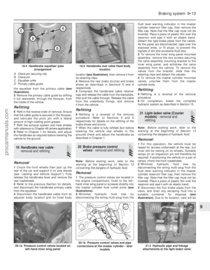 188
188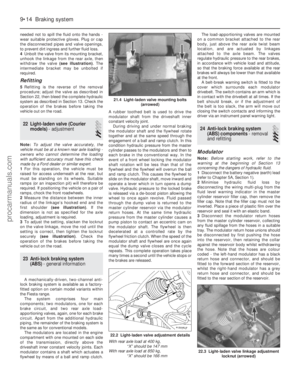 189
189 190
190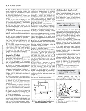 191
191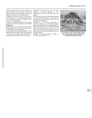 192
192 193
193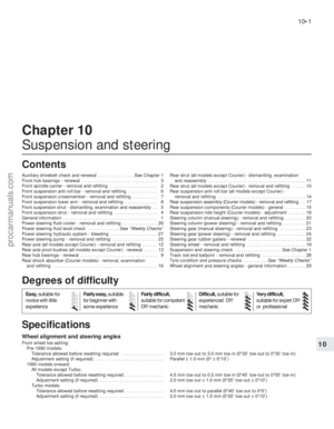 194
194 195
195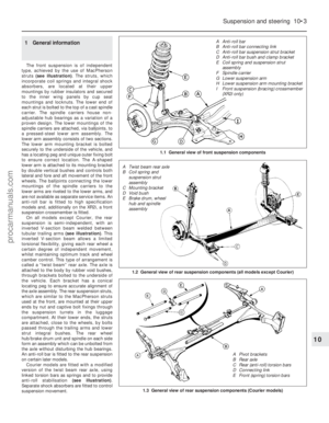 196
196 197
197 198
198 199
199 200
200 201
201 202
202 203
203 204
204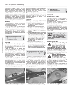 205
205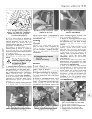 206
206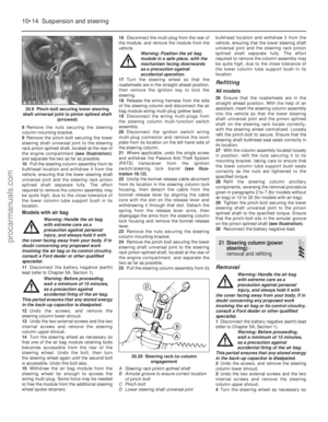 207
207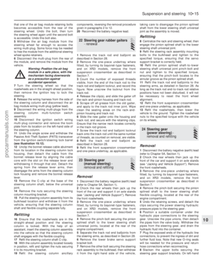 208
208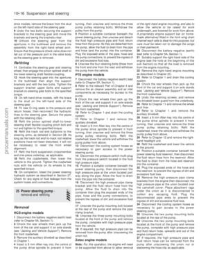 209
209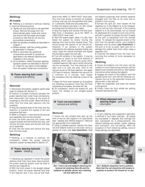 210
210 211
211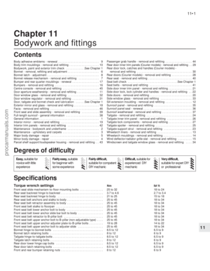 212
212 213
213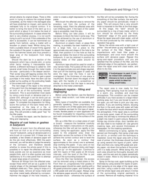 214
214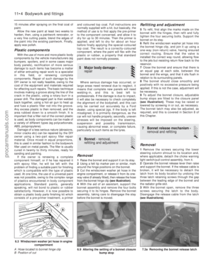 215
215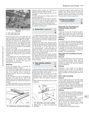 216
216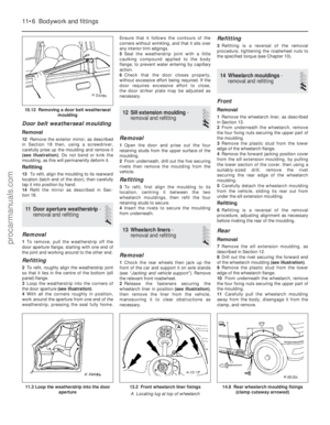 217
217 218
218 219
219 220
220 221
221 222
222 223
223 224
224 225
225 226
226 227
227 228
228 229
229 230
230 231
231 232
232 233
233 234
234 235
235 236
236 237
237 238
238 239
239 240
240 241
241 242
242 243
243 244
244 245
245 246
246 247
247 248
248 249
249 250
250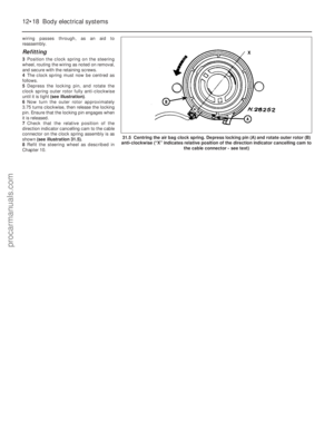 251
251 252
252 253
253 254
254 255
255 256
256 257
257 258
258 259
259 260
260 261
261 262
262 263
263 264
264 265
265 266
266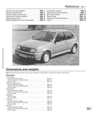 267
267 268
268 269
269 270
270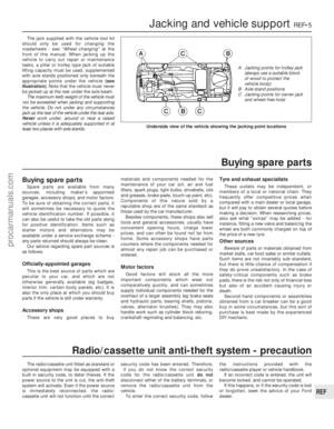 271
271 272
272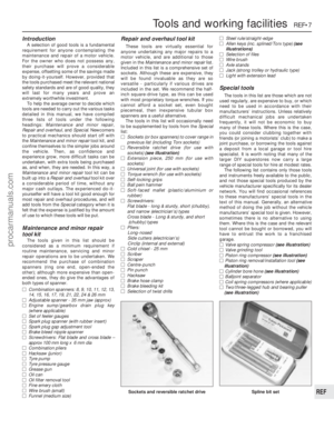 273
273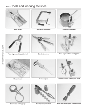 274
274 275
275 276
276 277
277 278
278 279
279 280
280 281
281 282
282 283
283 284
284 285
285 286
286 287
287 288
288 289
289 290
290 291
291 292
292 293
293 294
294 295
295