Page 241 of 296
 .
22 All bulbs are of bayonet type fitting.
23 Refitting is a reversal of the removal
procedure.
Rear light cluster (Courier
models)
24 Workin")
the bulbholder together and remove it (see
illustrations) .
22 All bulbs are of bayonet type fitting.
23 Refitting is a reversal of the removal
procedure.
Rear light cluster (Courier
models)
24 Working inside the load compartment,
unscrew the two black plastic nuts securing
the light cluster assembly. Withdraw the
assembly to the outside of the vehicle,
disconnecting the wiring from the bulbholder
(see illustrations) .
25 All bulbs are of bayonet type fitting.
26 Refitting is a reversal of the removal
procedure.
Number plate lights
27 Insert a thin flat-bladed screwdriver
between the light assembly and the bumper,
and carefully prise the light out. Use a rag, or
a piece of card, between the screwdriver and
the bumper, to prevent damage to the
bumper.
28 Detach the connections on the underside
of the light assembly.
29 Release the tab securing the light cover to
the bulbholder, and remove the cover (see
illustration) .
30 The bulb is a bayonet type fitting in its
holder.
31 Refitting is a reversal of the removal
procedure.
6 Bulbs (interior lights) -
renewal
2
Instrument panel illumination
and warning lights
1 Refer to Section 10.
Automatic transmission selector
illumination
2Using a thin flat-bladed screwdriver, prise
up the selector cover and remove it.
3 Pull the bulb assembly to release it from the
selector lever, then remove its cover. The bulb
is a bayonet fit in its holder (see illustrations).
4 Refitting is a reversal of the removal
procedure.
Hazard warning switch
5 The hazard warning light switch, an integral
part of the steering column multi-function
switch assembly, has a bulb cover which pulls
off. The bulb is removed by pulling it from its
location.
6 Refitting is a reversal of the removal
procedure.
Clock illumination
7 Carefully prise the clock out of its facia
location, as described in Section 13.
8 Twist the bulbholder and withdraw it from
the rear of the clock (see illustration). Note
12•8Body electrical systems
6.8 Withdrawing the clock illumination
bulb and its integral holder from the rear of
the clock6.3b . . . followed by the (bayonet fitting) bulb6.3a Remove the selector illumination bulbcover . . .
5.29 Release the number plate light
securing tab (arrowed) and separate the bulbholder and light cover5.24b . . . then withdraw the assembly to
the outside of the vehicle
5.24a On Courier models, unscrew the twoblack plastic nuts securing the rear light cluster assembly . . .5.21b . . . then having pressed its retaininglugs, withdraw the bulbholder for access to the bulbs5.21a Disconnect the ear light clustermulti-plug from the bulbholder . . .
1595Ford Fiesta Remakeprocarmanuals.com
http://vnx.su
Page 242 of 296

that the bulb and bulbholder cannot be
separated - they are replaced as an assembly.
9Refitting is a reversal of the removal
procedure.
Cigarette lighter illumination
10 Remove the cigarette lighter, as described
in Section 12.
11 Pull the bulbholder from its location in the
illuminated surround, then pull the bulb out of
the bulbholder.
12 Refitting is a reversal of the removal
procedure.
Heater facia illumination
13 Pull the heater fan motor control knob off,
then move the air distribution and
temperature controls fully to the right. Unclip
and remove the heater slide facia towards the
left-hand side of the vehicle, removing the
slide control knobs only as necessary, and
disconnecting its bulbholder (bayonet type) as
it is withdrawn (see illustration) .
14 The bulb is removed by pulling it from its
bulbholder.
15 Refitting is a reversal of the removal
procedure.
Interior (courtesy) light
16 Insert a thin flat-bladed screwdriver into
the slot in the light assembly, and carefully
lever it out of its aperture. The bulb is a
bayonet fit (see illustrations) .
17 Refit the bulb by reversing the method of removal, then insert the switch end of the light
to the aperture, pivot the light upwards and
push home to secure.
Luggage compartment
(courtesy) light
18
Carefully prise the luggage compartment
(courtesy) light assembly out of its location,
using a thin flat-bladed screwdriver. Twist the
bulbholder anti-clockwise to remove.
19 The bulb is removed by pulling it from its
bulbholder.
20 Refitting is a reversal of the removal
procedure.
7 Exterior light units -
removal and refitting
2
1 Disconnect the battery negative (earth) lead
(refer to Chapter 5A, Section 1), before
removing any of the light units.
Headlight
2 Disconnect the multi-plug from the back of
the headlights (see illustration) .
3 Twist the sidelight bulb holder to release,
then withdraw it.
4 Remove the headlight securing bolt and
depress the headlight retaining spring, to
allow the headlight assembly to be hinged forwards and out of its location
(see
illustration) .
5 Refitting is a reversal of the removal
procedure, ensuring that the lower headlight
mounting guide is inserted correctly, and that
the retaining spring engages fully (see
illustration) .
6 On completion, check the headlight beam
alignment as described in Section 8.Front direction indicator
7 To remove, release the indicator light
retaining spring from its body location, then
pull the light assembly forwards and
disconnect its multi-plug as it is withdrawn
(see illustrations) .
Body electrical systems 12•9
6.16b Interior (courtesy) light pivoted for
access to the bulb
7.2 Disconnecting the multi-plug from the
back of the headlight
6.16a Releasing the interior (courtesy)light from its location6.13 Heater fan illumination arrangement
7.7a Release the front direction indicatorlight retaining spring from its body
location . . .7.5 Refitting the headlight. Mountingguides (A) to fit to panel (B)7.4 Headlight retaining bolt (A), andretaining spring arrangement (B)
12
1595Ford Fiesta Remakeprocarmanuals.com
http://vnx.su
Page 243 of 296

8Refitting is a reversal of the removal
procedure.
Front direction indicator side
repeater
9 Remove the appropriate front wheel arch
liner as described in Chapter 11.
10 Remove the appropriate sill scuff plate as
described in Chapter 11, and release the clip
securing the insulation to the panel forward of
the lower A-pillar.
11 Disconnect the supply lead connector and
the earth lead, then release their grommet
from its panel location.
12 From outside the vehicle, twist the light
assembly to release it, then withdraw it and its
leads.
13 Refitting is a reversal of the removal
procedure, ensuring that the grommet is
seated correctly in its panel location.
Rear light cluster
14 Disconnect the multi-plug from the
bulbholder, then press the retaining lugs on
the bulbholder together and remove it (see
illustration) . 15
Unscrew the four nuts securing the light
unit, then remove the unit and its seal.
16 Refitting is a reversal of the removal
procedure. Tighten the light unit securing nuts
to their specified torque.
Number plate light
17 Insert a thin flat-bladed screwdriver
between the light assembly and the bumper,
and carefully prise the light out. Use a rag, or
a piece of card, between the screwdriver and
the bumper, to prevent damage to the
bumper.
18 Detach the connections on the underside
of the light assembly.
19 Refitting is a reversal of the removal
procedure.
Auxiliary lights
S models
20 Disconnect the battery negative (earth)
lead (refer to Chapter 5A, Section 1).
21 Disconnect the light wiring multi-plug then
unscrew its retaining nut, withdraw the bolt
and remove the light unit (see illustration).22
Refitting is a reversal of the removal
procedure, tightening the retaining nut to the
specified torque. On completion, check the
auxiliary light beam alignment as described in
Section 8.
XR2i models
23 Disconnect the battery negative (earth)
lead (refer to Chapter 5A, Section 1).
24 Undo the four Torx retaining screws
securing the relevant dual light assembly to its
bumper location. Note that the retaining and
adjusting screws are captive within the light
assembly - they cannot be removed from
the assembly (see illustration) .
25 Withdraw the light assembly from its
location, then remove the caps protecting the
bulbs and disconnect the wiring.
26 If required, the lights may be removed
individually from their housing at this stage.
Each light is secured to its housing unit by a
combination of two types of clips - foglight
retention differs from driving light retention.
27 The adjusting/retaining clips are removed
by undoing the adjustment screws on the
front of the housing unit, then turning the clips
using pliers or similar tool, before
withdrawing. To remove a retaining-only clip,
lift the lug on the side of the clip using a
screwdriver, then turn the clip using pliers or
similar tool, before withdrawing.
28 Refitting is a reversal of the removal
procedure. On completion, check the auxiliary
light beam alignment as described in Section 8.
8 Headlight and auxiliary light
beam alignment - checking
and adjustment
2
1 Accurate adjustment of the headlight and
auxiliary light beams is only possible using
optical beam-setting equipment, and this
12•10 Body electrical systems
7.24 Auxiliary light assembly (XR2i models) - left-hand unit shown
A Light assembly retaining screws
B Fog light vertical adjustment screw
C Driving light vertical adjustment screw D Driving light horizontal
adjustment screw
E Bulb protective caps
F Fog light bulb connector
G Bulb earth leads
H Driving light bulb connector
7.21 Auxiliary light fixture (S models)
A Bracket retaining nuts C Auxiliary light multi-plug
B Auxiliary light retaining nut
7.14 Press the retaining lugs on the rear
light cluster bulbholder together (broken arrows) to release the bulbholder7.7b . . . then pull the light unit out to
enable the multi-plug (arrowed) to be disconnected
1595Ford Fiesta Remakeprocarmanuals.com
http://vnx.su
Page 244 of 296

work should therefore be carried out by a
Ford dealer or service station with the
necessary facilities.
2Temporary adjustment can be made when
the headlight has been removed and refitted,
or to compensate for normal adjustment
whenever a heavy load is being carried. Turn
the adjustment screws at the rear of the
headlight unit to make the adjustment (see
illustration) .
3 Before making any adjustments to the
headlight settings, it is important that the tyre
pressures are correct, and that the vehicle is
standing on level ground. Bounce the front of
the vehicle a few times to settle the
suspension. Ideally, somebody of normal size
should sit in the driver’s seat during the
adjustment, and the vehicle should have a full
tank of fuel.
4 S model auxiliary lights are adjusted by
slackening the light retaining nuts and
swivelling the light assemblies (see
illustration 7.21) . Tighten the nuts upon
completion.
5 XR2i model auxiliary lights are individually
adjustable within their housings, provision
being made for both vertical and horizontal
adjustment of the driving lights, and vertical adjustment only of the foglights. Adjustment is
made via Torx-head captive screws on the
front of the housings
(see illustration 7.24) .
6 Whenever temporary adjustments are
made, the settings must be reset as soon as
possible once the vehicle is in normal use.
9 Instrument panel -
removal and refitting
2
Removal
1 Disconnect the battery negative (earth) lead
(refer to Chapter 5A, Section 1).
2 Disconnect the speedometer cable at the
transmission casing (see Section 11).
3 Remove the two screws securing the
instrument panel bezel from its underside.
Remove the bezel.
4 Remove the four screws securing the
instrument panel to its location, then carefully
pull it out to allow access to the speedometer
cable and multi-plug connections. Disconnect
the speedometer cable and multi-plug, then
remove the instrument panel from the vehicle
(see illustrations) .
Refitting
5Refitting is a reversal of removal. On
completion check the function of all electrical
components.
10 Instrument panel
components -
removal and refitting
1
Removal
1 Remove the instrument panel as described
in Section 9.
Panel illumination and warning light
bulbs
2 All bulbholders are a bayonet fit, requiring a
“twist and withdraw” removal technique (see
illustration) . Bulbs cannot be removed from
their holders -they are renewed complete.
Printed circuit
3 Insert a thin flat-bladed screwdriver into the
multi-plug retainer and carefully unclip it,
having noted its orientation (see illustration).
4 Remove all panel illumination and warning
light bulbholders.
5 Using a suitable tool (a trim clip removal
tool is ideal), carefully prise the printed circuit
off its instrument terminals, and release it from
its retainers before removing.
Speedometer
6 Remove the two bulbholders on the top of
the panel assembly, and release their strip of
printed circuit from its retainers, so that the
instrument panel halves may be separated.
7 Separate the panel halves by releasing the
Body electrical systems 12•11
9.4b Disconnect the speedometer cable
from the rear of the instrument cluster . . .9.4a Instrument cluster securing screws (arrowed)8.2 Exploded view of the headlight unit
A Sidelight bulb holder
B Sidelight bulb
C Headlight bulb retainer
D Headlight bulb
E Bulb protective cap
F Horizontal adjustment screw
G Vertical adjustment screw
10.3 Unclipping the multi-plug retainer from the rear of the instrument cluster10.2 Removing a bulbholder from the rear of the instrument cluster (bayonet type
fitting)9.4c . . . then disconnect the multi-plug
12
1595Ford Fiesta Remakeprocarmanuals.com
http://vnx.su
Page 245 of 296
 .
8 Remove its two Torx-head retaining
screws, then detach and withdraw the
speedometer from")
retaining tags, taking care to avoid damaging
or losing the warning light graphic strips (see
illustration) .
8 Remove its two Torx-head retaining
screws, then detach and withdraw the
speedometer from the front of the assembly.
Tachometer
9 Carry out the procedure given in
paragraphs 6 and 7.
10 Carefully prise the printed circuit from the
tachometer terminals, using a similar method
to that described in paragraph 5, releasing it
from its retainers as necessary.
11 Remove its two Torx-head retaining
screws, then unclip and withdraw the
tachometer from the front of the assembly.
Fuel and temperature gauge
assembly
12 Removal and refitting procedures are
similar in method to those for the tachometer,
but only one Torx-head screw retains the
assembly.
Refitting
13 Refitting is a reversal of removal.
11 Speedometer cable -
removal and refitting
2
Removal
1 Remove the instrument panel as described
in Section 9.
2 Unscrew the speedometer cable from the
pinion/speed sensor on the transmission (see
illustration) .
3 Release the cable-ties and retaining clips in
the engine compartment, and withdraw the
cable grommet from the bulkhead. 4
Note the cable routing for use when
refitting. Pull the speedometer cable through
into the engine compartment, and remove it
from the car.
Refitting
5 Refitting is the reversal of removal. Ensure
that the cable is routed as noted before
removal, secured with the relevant clips and
cable-ties, and that the grommet is properly
located in the bulkhead.
12 Cigarette lighter -
removal and refitting
1
Removal
1 Disconnect the battery negative (earth) lead
(refer to Chapter 5A, Section 1).
2 Remove the cigarette lighter element
(heated section).
3 Carefully prise the element barrel out from
the illuminated surround, disconnecting its
multi-plug as it is withdrawn.
4 Hinge the illuminated surround out
carefully, removing its bulb feed connector as
it is withdrawn.
Refitting
5 Refitting is a reversal of the removal
procedure.
13 Clock -
removal and refitting
1
Removal
1 Disconnect the battery negative (earth) lead
(refer to Chapter 5A, Section 1).
2 Using a thin flat-bladed screwdriver,
carefully prise the clock out of the facia (see
illustration) . Use a piece of card or similar to
prevent damage to the facia. Withdraw the
clock so that its multi-plug may be
disconnected, then remove it from the vehicle.
Refitting
3 Refitting is a reversal of removal. Reset the
clock on completion.
14 Horn -
removal and refitting
1
Removal
1 The horn is mounted forward on the left-
hand side of the engine compartment, near
the battery.
2 Disconnect the battery negative (earth) lead
(refer to Chapter 5A, Section 1).
3 Remove the wiring loom connection from
the horn(s).
4 Both single and dual horns are mounted to
a bracket which is secured to the bodywork
by a single bolt. Remove the bolt and
withdraw the horn(s) and bracket from the
vehicle. The horn(s) may be separated from
the bracket, as required, by removing the
retaining nut(s).
Refitting
5 Refitting is a reversal of removal.
15 Wiper arms -
removal and refitting
1
Removal
1 With the wiper(s) “parked” (ie in the normal
at-rest position), mark the positions of the
blade(s) on the screen, using a wax crayon or
strips of masking tape.
2 Lift up the plastic cap from the bottom of
the wiper arm, and loosen the nut one or two
turns.
3 Lift the wiper arm, and release it from the
taper on the spindle by moving it from side to
side.
4 Completely remove the nut and washer,
then withdraw the wiper arm from the
spindle.
Refitting
5 Refitting is a reversal of the removal
procedure. Make sure that the arm is fitted in
the previously-noted position.
12•12 Body electrical systems
13.2 Carefully prise the clock out of the facia11.2 Detaching the speedometer cable atthe transmission casing10.7 Rear view of instrument cluster
A Retaining tags
B Multi-plug retainer
C Speedometer cable connection
D Speedometer gauge retaining screws
E Tachometer terminals (obscured by protective pad)
F Tachometer gauge retaining screws
G Fuel and temperature gauge assembly
terminals
H Fuel and temperature gauge assembly retaining screw
1595Ford Fiesta Remakeprocarmanuals.com
http://vnx.su
Page 246 of 296

16 Windscreen wiper motor andlinkage - removal and refitting
2
Removal
Wiper motor
1Operate the wiper motor, then switch it off
so that it returns to its rest position.
2 Disconnect the battery negative (earth) lead
(refer to Chapter 5A, Section 1).
3 Dependent on model, disconnect and
remove the air cleaner components as
necessary to allow access to remove the
bulkhead panel.
4 Remove the cooling system expansion tank
as described in Chapter 3.
5 Release the wiring loom, any connectors,
cable-ties and hoses from the right-hand half
of the bulkhead panel, then remove its rubber
seal.
6 The right-hand half of the bulkhead panel is
secured by screws and a single nut. The nut is
located behind the panel at the bonnet hinge
end. Release the right-hand half of the panel
and, having ensured that it is free to move,
remove it (see illustrations) .
7 Unscrew the nut from the driving shaft, and
pull the crank off the driving shaft taper (see
illustration) .
8 Undo the three wiper motor retaining bolts and withdraw the motor assembly
(see
illustrations) . Remove the motor cover, then
disconnect the multi-plug and remove the
motor from the vehicle.
Linkage
9 Pull the rubber seal off the bulkhead panel.
10 Bring the windscreen wiper linkage to an
accessible position, using the ignition switch
as a means of stopping the wiper motor
returning to the parked position.
11 Disconnect the battery negative (earth)
lead (refer to Chapter 5A, Section 1).
12 Prise the linkages off their ball pivots as
required, using a suitably-sized open-ended
spanner. The crank has a dual (vertically
stacked) ball pivot with a bellows separating
the two linkages (see illustrations) .
13 If the running faces of the ball pivots are
damaged, the pivot shaft(s) or crank must be
renewed.
Refitting
Wiper motor
14 Refitting is a reversal of the removal
procedure, tightening all nuts and bolts to the
specified torque. Refit the expansion tank as
described in Chapter 3.
Linkage
15 Prior to refitting, grease the ball pivot
sockets on the linkages, then locate them on
their appropriate ball pivots and press into position using a suitably-sized socket. The
bellows between the two linkages on the
crank must also be greased using the
specified lubricant. Refit the bulkhead panel
rubber seal on completion.
17 Windscreen wiper pivot
shaft - removal and refitting
2
Removal
1Remove the windscreen wiper arms as
described in Section 15.
Body electrical systems 12•13
16.7 Unscrew the nut from the wiper motor driving shaft16.6b . . . then disengage the right-handhalf of the panel from under its single retaining nut (left-hand shown)16.6a Remove all retaining screws from
the right-hand half of the bulkhead panel (upper centre screw shown) . . .
16.12b Windscreen wiper motor bracketwith linkage and motor. Inset shows
bellows arrangement (A)
16.8a With the crank removed from the
driving shaft taper, undo the three wiper motor retaining bolts (arrowed)
16.12a Windscreen wiper linkage
A Removal B Refitting16.8b . . . and withdraw the wiper motor assembly
12
1595Ford Fiesta Remakeprocarmanuals.com
http://vnx.su
Page 247 of 296

2Carry out the procedure detailed in Sec-
tion 16, paragraphs 2 to 6.
3 Remove the collars from the pivot shafts,
unscrew the pivot shaft securing nuts and
remove the washers and outer rubber bushes
(see illustration) .
4 Undo the two wiper motor bracket securing
bolts and remove the bracket assembly from
the vehicle, disconnecting the multi-plug
from the motor as the assembly is withdrawn
(see illustration) .
5 Remove the inner rubber bush from the
pivot shaft being renewed, and disconnect its
linkage as described in paragraph 12 of the
previous Section.
6 Remove the circlip, washers, shims and O-
ring, keeping them in order for refitting, and
withdraw the pivot shaft from the wiper motor
bracket assembly.
Refitting
7 Refitting is a reversal of the removal
procedure, greasing the pivot shaft with the
specified lubricant before inserting it to its
location. Refer to paragraph 15 in the previous
Section before refitting the linkage. Reference
must also be made to the Specificationsfor
details of tightening torques.
8 Refit the windscreen wiper arms in
accordance with Section 15. Refit the
expansion tank as described in Chapter 3.
18 Tailgate wiper motor assembly -
removal and refitting
1
Removal
1 Operate the wiper, then switch it off so that
it returns to its rest position. Note that the
wiper motor will only operate with the tailgate
shut, as the spring-tensioned connector pins
must be in contact with the contact plates.
2 Disconnect the battery negative (earth) lead
(refer to Chapter 5A, Section 1).
3 Remove the wiper arm with reference to
Section 15. 4
Remove the tailgate trim panel as
described in Chapter 11.
5 Disconnect the wiper motor multi-plug and
earth lead, then undo the three bolts securing
the wiper motor bracket, and remove the
assembly from the vehicle (see illustration).
6 The wiper motor may be separated from its
bracket by undoing the three mounting bolts
securing it. Note washer/spacer and rubber
insulator fitment.
Refitting
7 Refitting is a reversal of the removal
procedure, ensuring that the wiper motor
shaft locates through its collar on the exterior
panel surface. Tighten all bolts to their
specified torque.
19 Windscreen/tailgate washer system components -
removal and refitting
1
Removal
Washer pump
1 Chock the rear wheels then jack up the front of the car and support it on axle stands
(see
“Jacking and vehicle support” ).
2 Withdraw the washer pump from the
reservoir, collecting the fluid in a suitable
container as the pump is removed. Note the
seal fitment (see illustration) .
3 Having noted hose fitment to pump
connectors, remove the multi-plug and hoses,
then remove the pump from the vehicle.
4 Examine the pump seal. If it is perished or
otherwise damaged, it should be replaced.
Reservoir
5 Disconnect the battery negative (earth) lead
(refer to Chapter 5A, Section 1).
6 Chock the rear wheels then jack up the
front of the car and support it on axle stands
(see “Jacking and vehicle support” ). Remove
the left-hand front roadwheel.
7 Remove the wheelarch liner as described in
Chapter 11.
8 Withdraw the windscreen/tailgate washer
pump from the reservoir with its hoses and
multi-plug attached, collecting the fluid in a
suitable container. Note the seal fitment.
9 Release the hoses and wiring from the
reservoir guide and remove the three reservoir
securing bolts (see illustration) . Remove the
reservoir.
12•14 Body electrical systems
19.9 Windscreen/tailgate washer reservoir
securing bolts (arrowed)
A In engine compartment
B In wheelarch (wheelarch liner removed)
19.2 Exploded view of windscreen/tailgate washer reservoir and pump components
A Cap
B Filter
C Reservoir
D Washer pump
E Pump seal F Tailgate washer
hose
G Windscreen
washer hose
(marked with
adhesive tape)
18.5 Tailgate wiper motor
A Wiper motor bracket retaining bolts
B Wiper motor and tailgate “contact fingers” multi- plugs
C Earth connection17.4 Removing the wiper motor bracket and linkage assembly (wiper motor removed)17.3 Windscreen wiper pivot shaft fixture
A Collar
B Pivot shaft securing nut
C Washer
D Outer rubber bush
E Inner rubber bush
1595Ford Fiesta Remakeprocarmanuals.com
http://vnx.su
Page 248 of 296

lead (refer to Chapter 5A, Section 1).
11 With the bonnet raised and supported on
its stay, release the fasteners securing it")
Windscreen washer jets and hoses
10Disconnect the battery negative (earth)
lead (refer to Chapter 5A, Section 1).
11 With the bonnet raised and supported on
its stay, release the fasteners securing its
insulation panel (where fitted). Remove the
insulation panel.
12 Carefully press in the retaining lugs on the
washer jets using a flat-bladed screwdriver,
then raise the washer jets from the exterior
surface of the bonnet and separate them from
their hoses
13 The windscreen washer jet hose may have
been fitted with a one-way (non-return) valve.
If this is the case, the main hose run sections
can be removed from either side of the valve
as required.
14 Chock the rear wheels then jack up the
front of the car and support it on axle stands
(see “Jacking and vehicle support” ).
15 Disconnect the windscreen washer hose
(marked with adhesive tape) from the washer
pump (see illustration 19.2) . Withdraw the
hose from the reservoir guide, and into the
engine compartment.
16 Release the hose from its clips in the
engine compartment, including the bonnet
hinge clip, release the hose grommet from the
bonnet (where fitted) and withdraw the hoses
from the bonnet (see illustration) .
Tailgate washer jet and hose
17Disconnect the battery negative (earth)
lead (refer to Chapter 5A, Section 1).
18 On XR2i models, remove the tailgate
spoiler as described in Chapter 11.
19 Remove the central blanking plug from
the upper interior surface of the tailgate, to
expose the washer jet base.
20 Depress the washer jet retaining lug using
a flat-bladed screwdriver, then push the
washer jet out through the panel. From the
outside, fully withdraw the washer jet and
disconnect it from its hose. Note washer jet
seal fitment.
21 Remove the left-hand sun visor.
22 Remove the left-hand A-pillar trim as
described in Chapter 11. 23
Release the left-hand side of the
headlining by removing the retaining
clips/grab handles/coat hooks, as applicable.
24 In the engine compartment, disconnect
the tailgate washer hose from its valve. The
forward hose run may be removed, if required,
in a manner similar to that described in
paragraphs 15 and 16 above, releasing it from
its clips in the engine compartment.
25 Remove the tailgate washer hose
grommet, then withdraw the hose through the
bulkhead into the passenger compartment.
26 Release the hose from its A-pillar and roof
frame locations. Release the grommet (hose
protector) from its tailgate and body locations,
and withdraw the hose from the vehicle.
Refitting
27 Refitting is a reversal of removal. Always
renew the pump-to-reservoir seal washer, and
ensure that all connections are securely
made. When reconnecting the pump hoses,
ensure that the hose marked with tape is
connected to the correspondingly marked
connection on the pump.
28 On completion, top-up the washer
reservoir ( “see Weekly checks” ) and check
that the operation of the washers is
satisfactory. If necessary, adjust the
windscreen washer jets by inserting a pin into
the centre of the jet and directing the flow at
the top part of the windscreen.
20 Electric window regulator motor - removal and refitting
3
Removal
1Remove the window regulator from the
vehicle, as described in Chapter 11.
2 To remove the motor from the regulator
mechanism, undo and remove the two Torx
head bolts securing it, then carefully separate
by unscrewing (see illustration) .
Refitting
3Carefully screw the motor shaft into the
regulator mechanism.
4 Temporarily connect the multi-plug, switch on the ignition and activate the motor, to
engage and pull the motor fully into the
regulator mechanism.
5
Ensure that the multi-plug connection is
located on top of the motor (as if the window
regulator is in position in the door), before
securing the motor to the regulator
mechanism with its two Torx-head bolts.
6 Switch off the ignition and disconnect the
multi-plug.
7 Refit the window regulator to the vehicle, in
accordance with Chapter 11.
21 Tailgate remote release motor - removal and refitting
2
Removal
1Disconnect the battery negative (earth) lead
(refer to Chapter 5A, Section 1).
2 Remove the tailgate inner trim panel as
described in Chapter 11.
3 Remove the two motor securing screws,
then twist the operating rod retaining clip and
withdraw the operating rod from it.
4 Disconnect the wiring and remove the
motor assembly.
5 The motor may be separated from its
bracket by removing two further screws.
Refitting
6 Refitting is a reversal of the removal
procedure.
22 Radio/cassette player -
removal and refitting
3
Removal
1 Disconnect the battery negative (earth) lead
(refer to Chapter 5A, Section 1).
2 Unscrew the four hexagonal head securing
pins from the corners of the unit with an Allen
key (see illustration) .
3 In order to release the radio retaining clips,
two U-shaped rods must be inserted into the
special holes on each side of the radio (see
Body electrical systems 12•15
19.16 Routing of washer hoses in the
engine compartment
A Windscreen washer hose
B Tailgate washer hose
C Tailgate washer hose one-way valve
22.2 Unscrewing the securing pins from the radio/cassette player20.2 Electrically operated window motor-securing bolts (A), and multi-plug
connection (B)
12
1595Ford Fiesta Remakeprocarmanuals.com
http://vnx.su
 1
1 2
2 3
3 4
4 5
5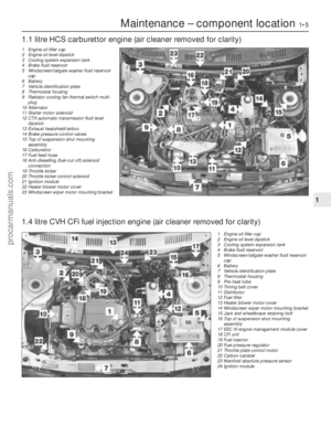 6
6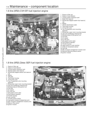 7
7 8
8 9
9 10
10 11
11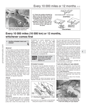 12
12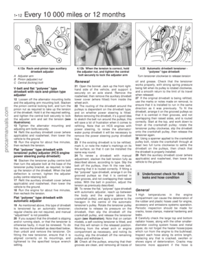 13
13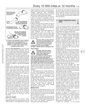 14
14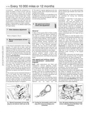 15
15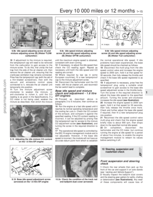 16
16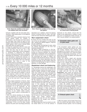 17
17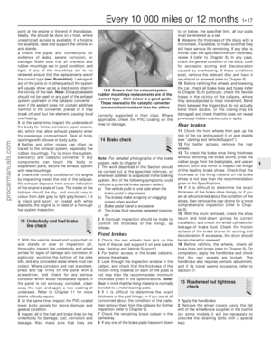 18
18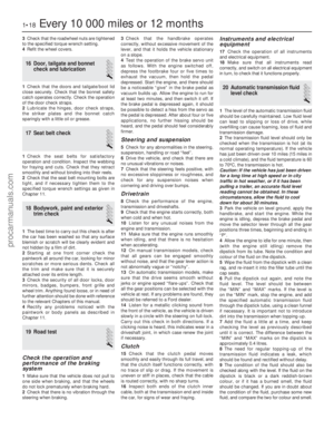 19
19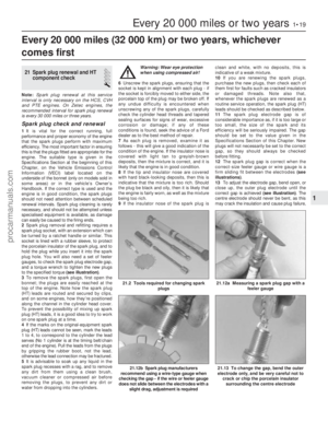 20
20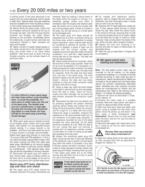 21
21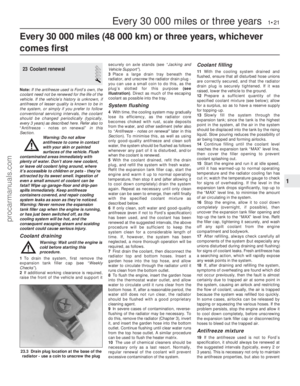 22
22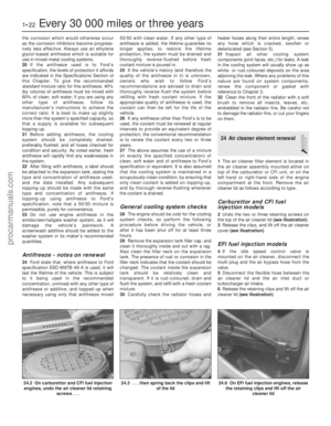 23
23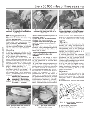 24
24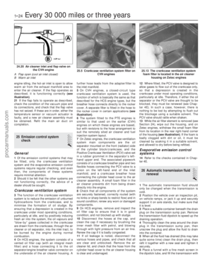 25
25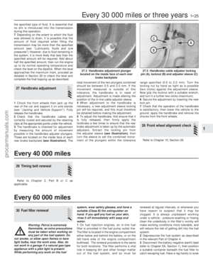 26
26 27
27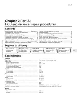 28
28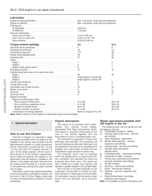 29
29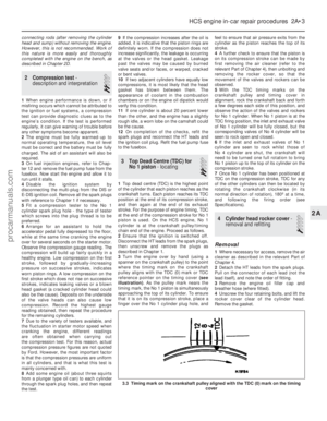 30
30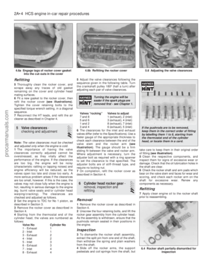 31
31 32
32 33
33 34
34 35
35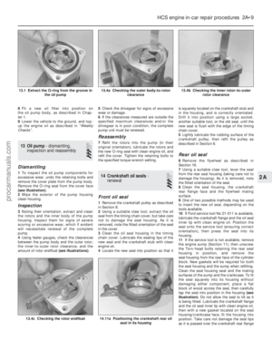 36
36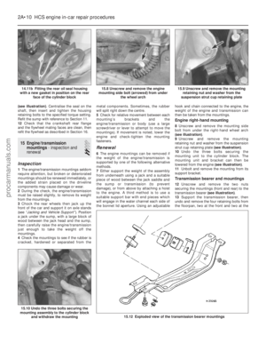 37
37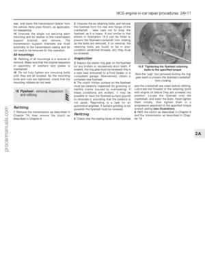 38
38 39
39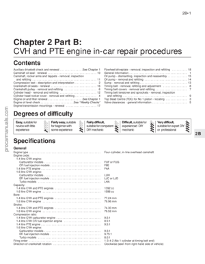 40
40 41
41 42
42 43
43 44
44 45
45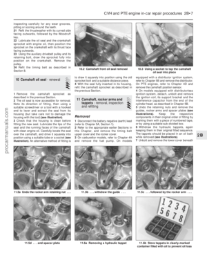 46
46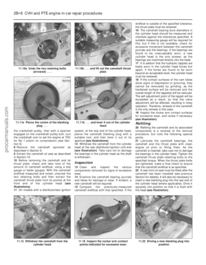 47
47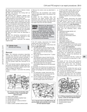 48
48 49
49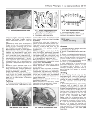 50
50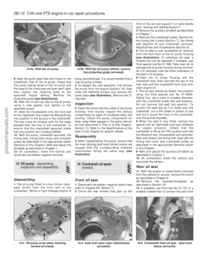 51
51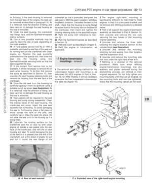 52
52 53
53 54
54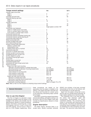 55
55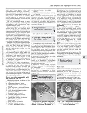 56
56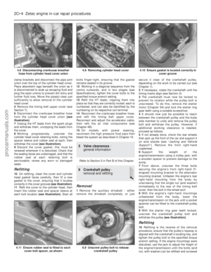 57
57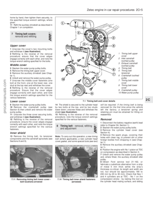 58
58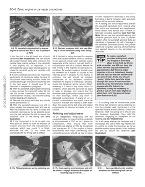 59
59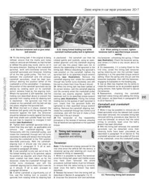 60
60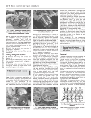 61
61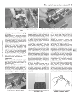 62
62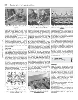 63
63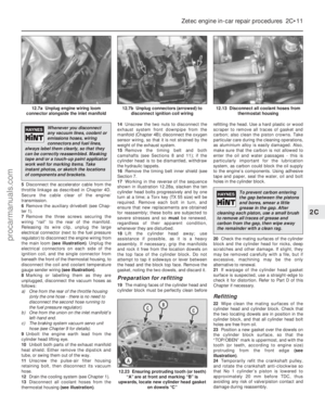 64
64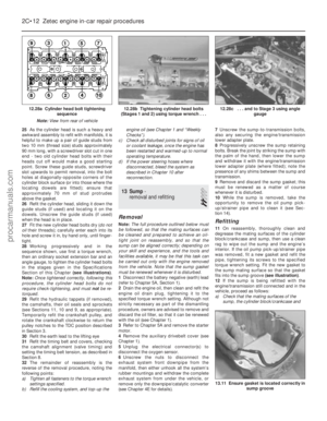 65
65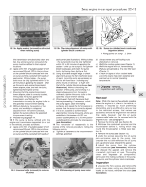 66
66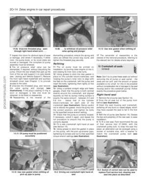 67
67 68
68 69
69 70
70 71
71 72
72 73
73 74
74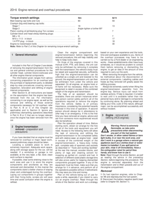 75
75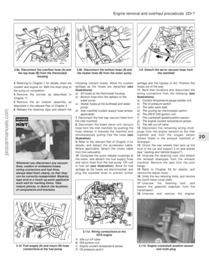 76
76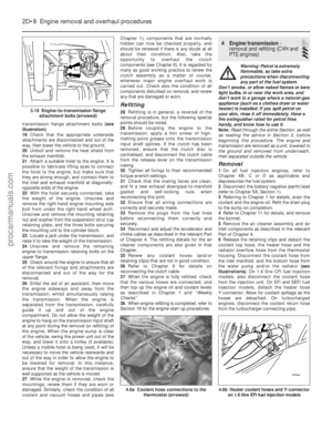 77
77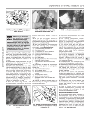 78
78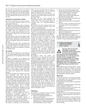 79
79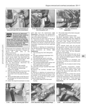 80
80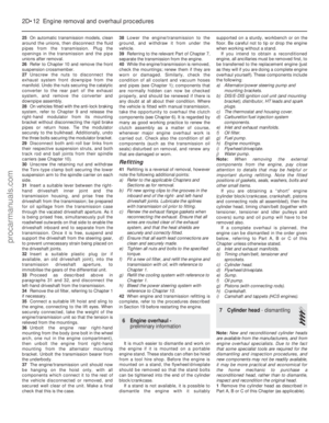 81
81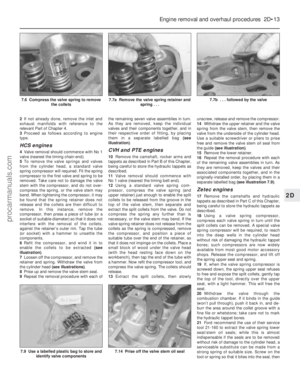 82
82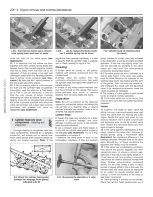 83
83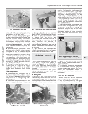 84
84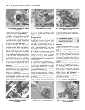 85
85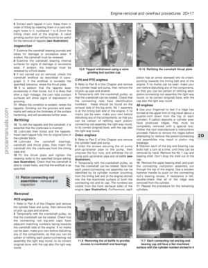 86
86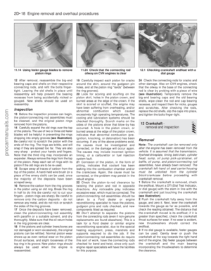 87
87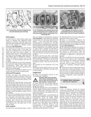 88
88 89
89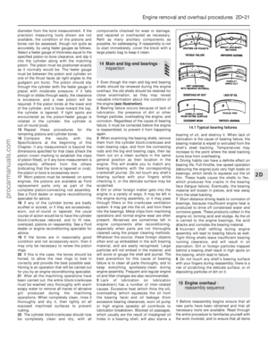 90
90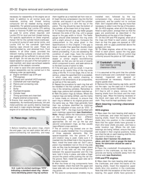 91
91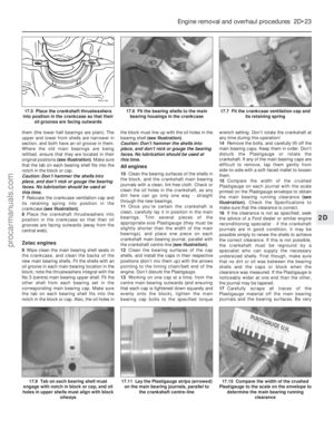 92
92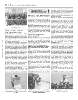 93
93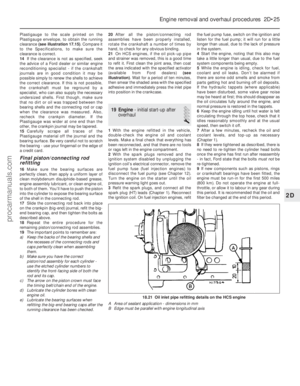 94
94 95
95 96
96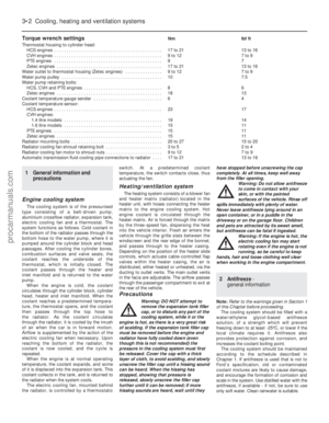 97
97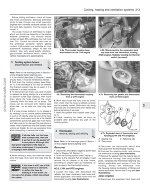 98
98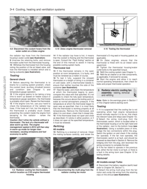 99
99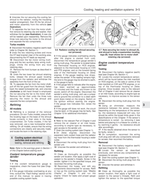 100
100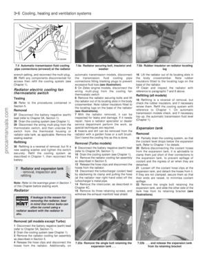 101
101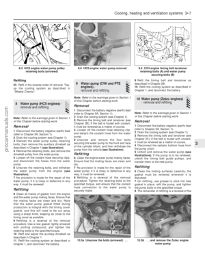 102
102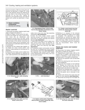 103
103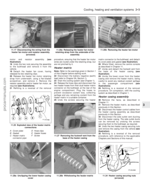 104
104 105
105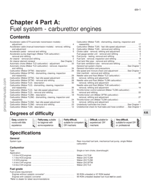 106
106 107
107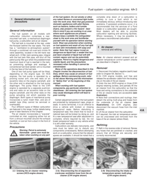 108
108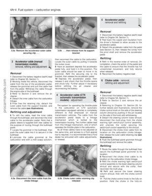 109
109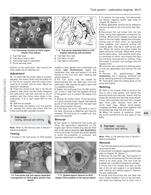 110
110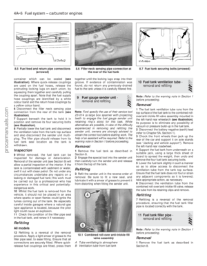 111
111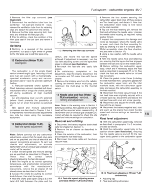 112
112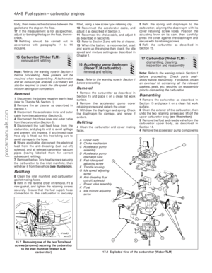 113
113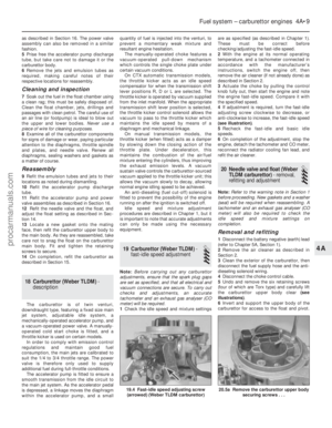 114
114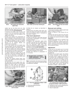 115
115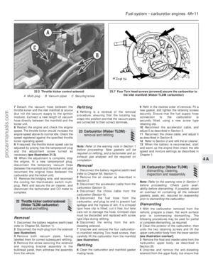 116
116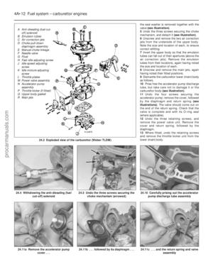 117
117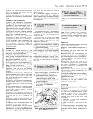 118
118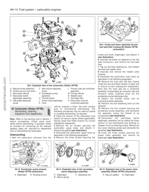 119
119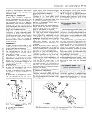 120
120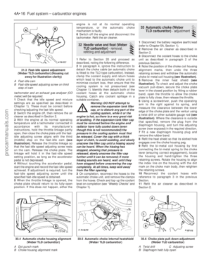 121
121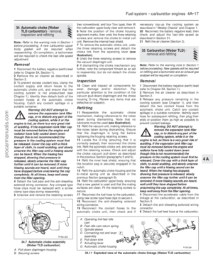 122
122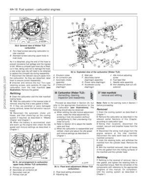 123
123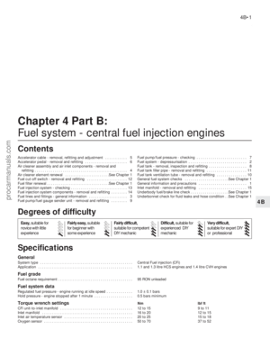 124
124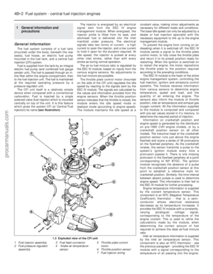 125
125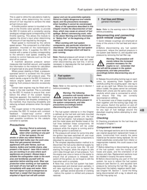 126
126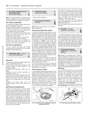 127
127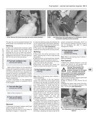 128
128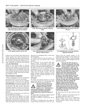 129
129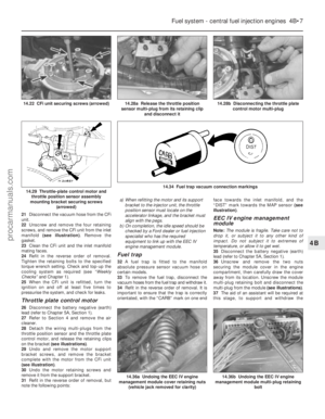 130
130 131
131 132
132 133
133 134
134 135
135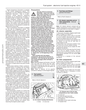 136
136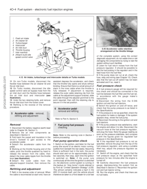 137
137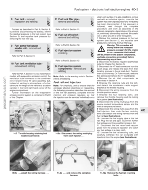 138
138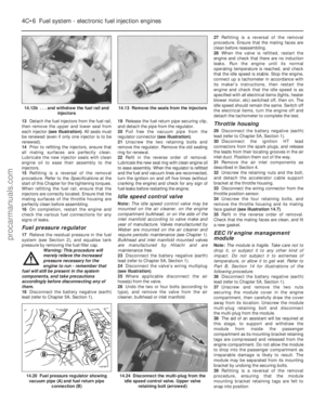 139
139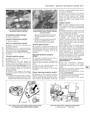 140
140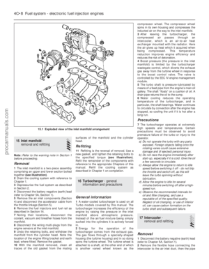 141
141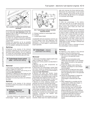 142
142 143
143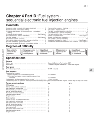 144
144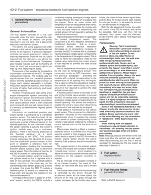 145
145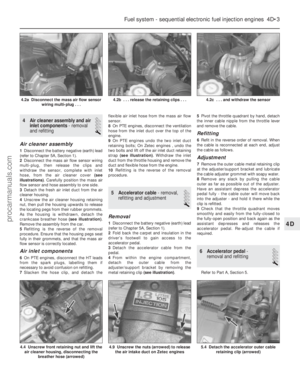 146
146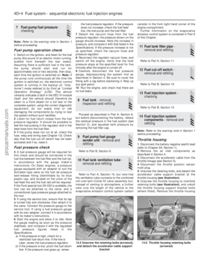 147
147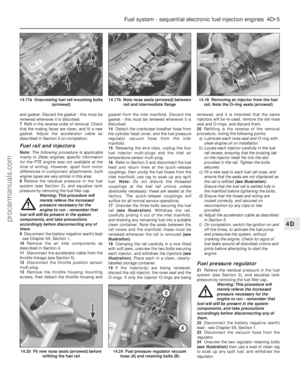 148
148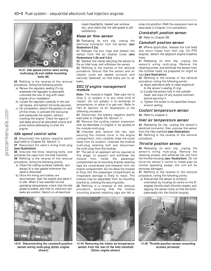 149
149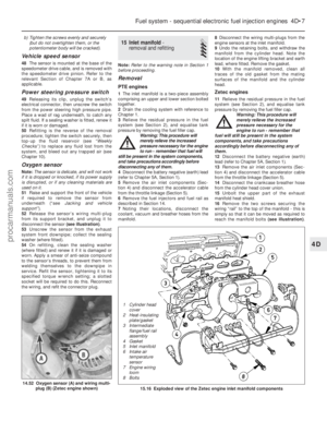 150
150 151
151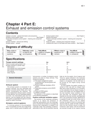 152
152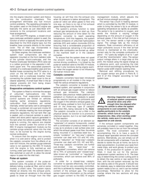 153
153 154
154 155
155 156
156 157
157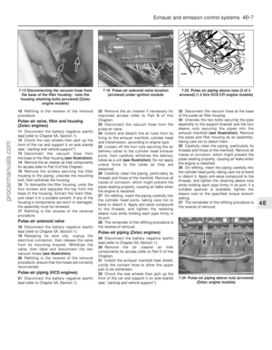 158
158 159
159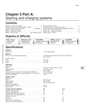 160
160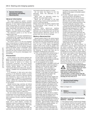 161
161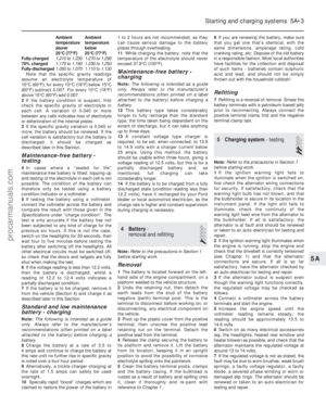 162
162 163
163 164
164 165
165 166
166 167
167 168
168 169
169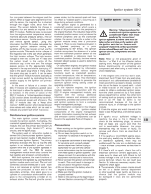 170
170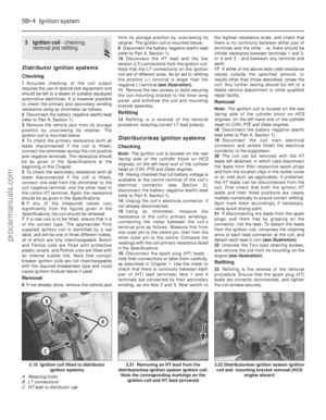 171
171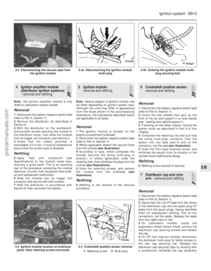 172
172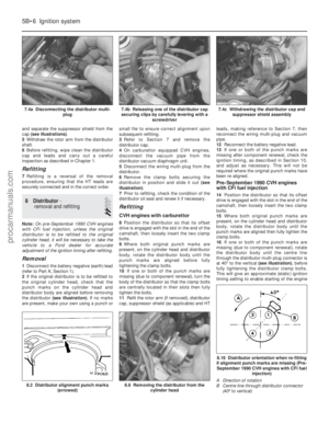 173
173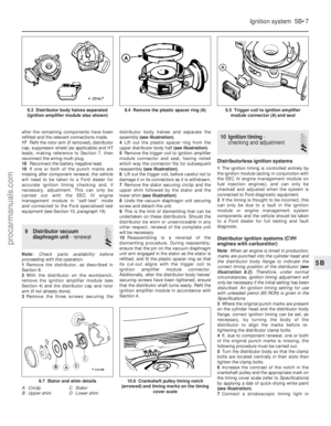 174
174 175
175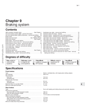 176
176 177
177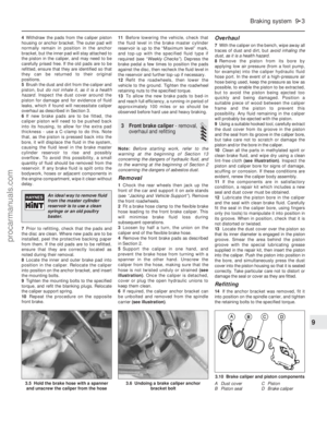 178
178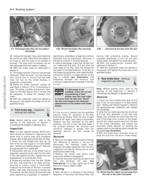 179
179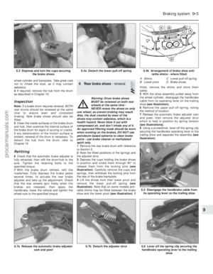 180
180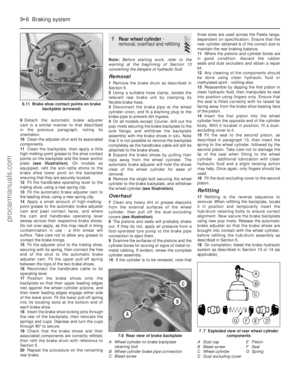 181
181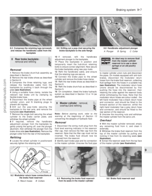 182
182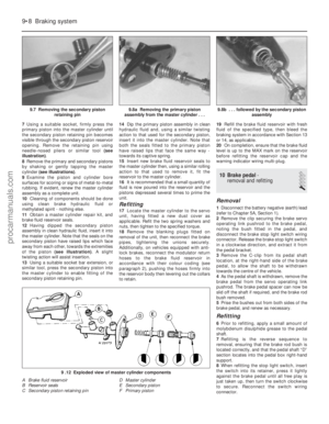 183
183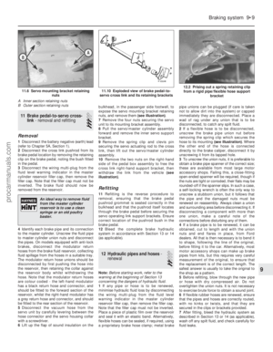 184
184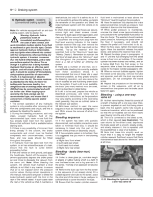 185
185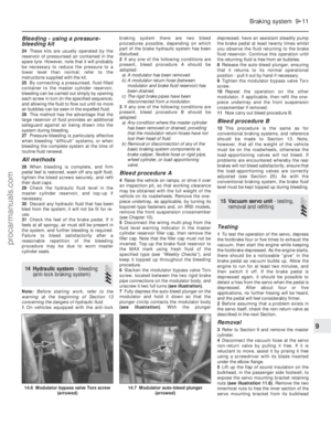 186
186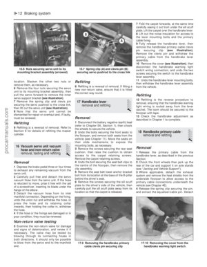 187
187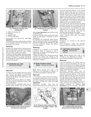 188
188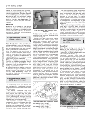 189
189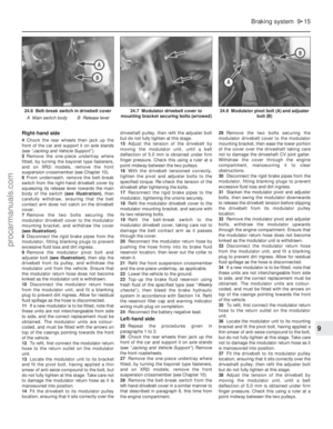 190
190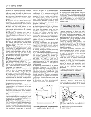 191
191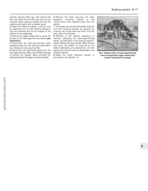 192
192 193
193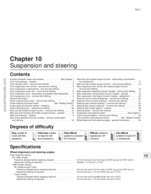 194
194 195
195 196
196 197
197 198
198 199
199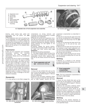 200
200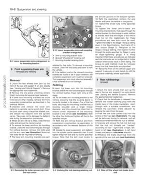 201
201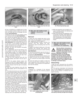 202
202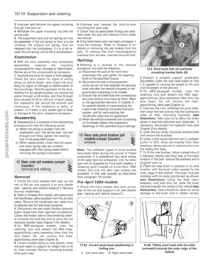 203
203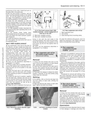 204
204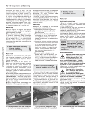 205
205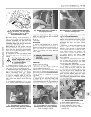 206
206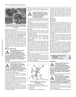 207
207 208
208 209
209 210
210 211
211 212
212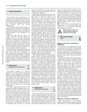 213
213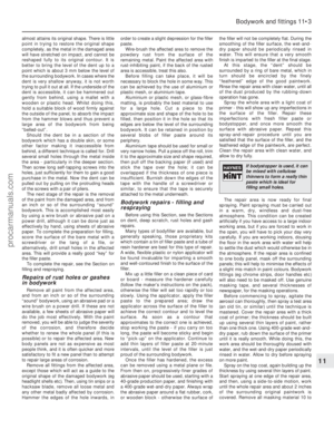 214
214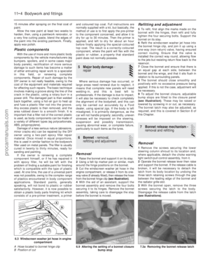 215
215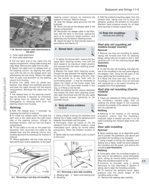 216
216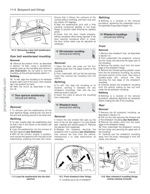 217
217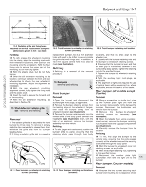 218
218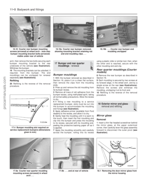 219
219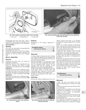 220
220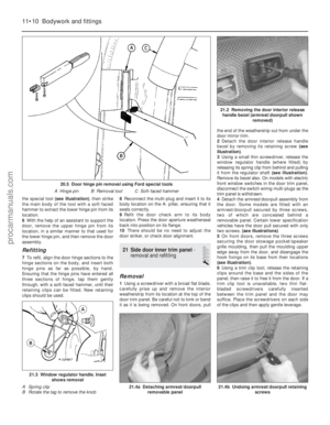 221
221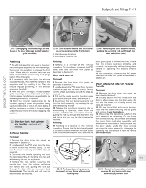 222
222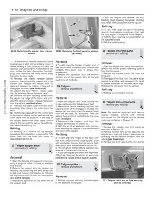 223
223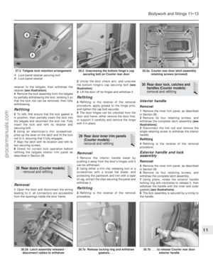 224
224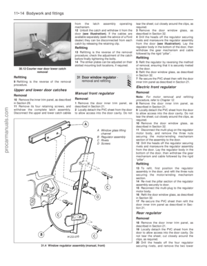 225
225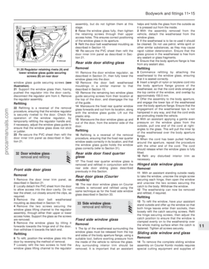 226
226 227
227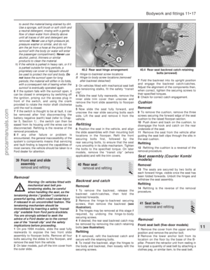 228
228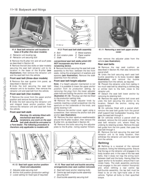 229
229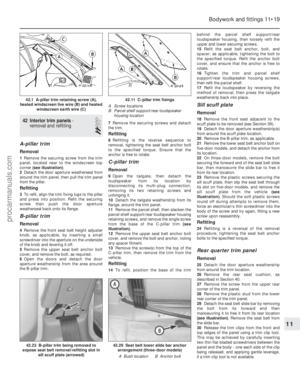 230
230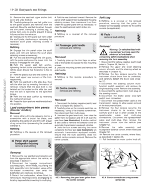 231
231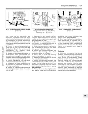 232
232 233
233 234
234 235
235 236
236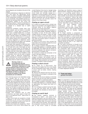 237
237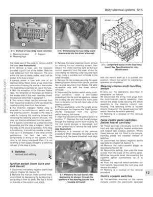 238
238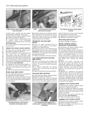 239
239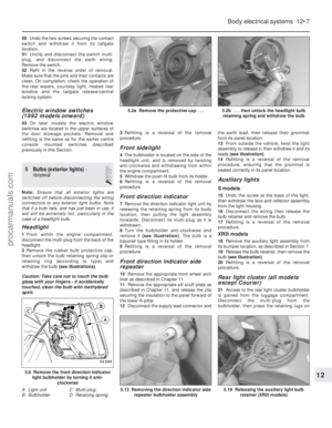 240
240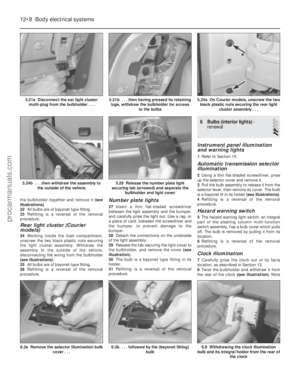 241
241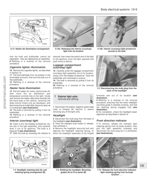 242
242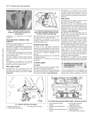 243
243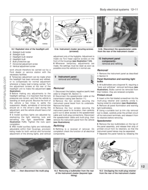 244
244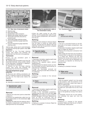 245
245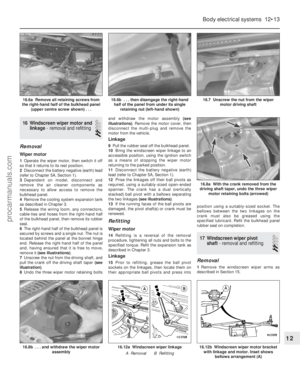 246
246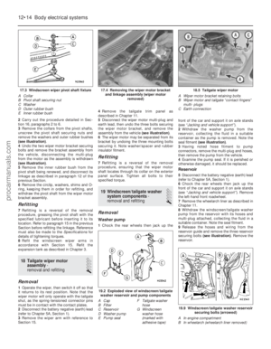 247
247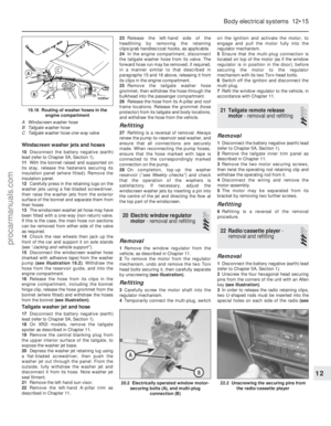 248
248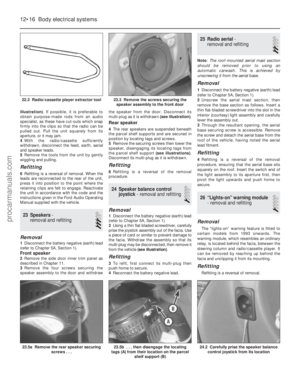 249
249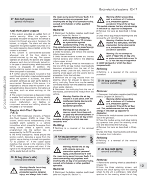 250
250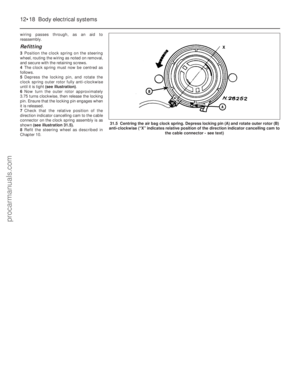 251
251 252
252 253
253 254
254 255
255 256
256 257
257 258
258 259
259 260
260 261
261 262
262 263
263 264
264 265
265 266
266 267
267 268
268 269
269 270
270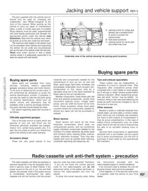 271
271 272
272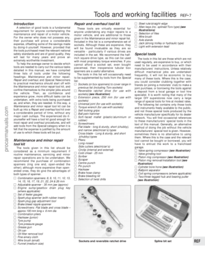 273
273 274
274 275
275 276
276 277
277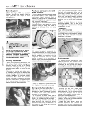 278
278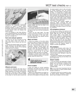 279
279 280
280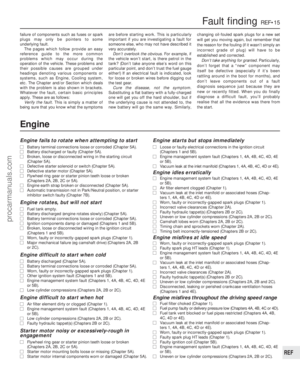 281
281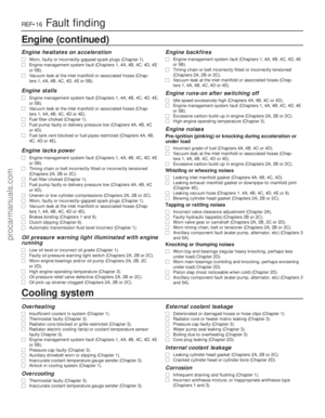 282
282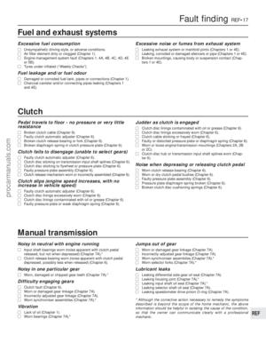 283
283 284
284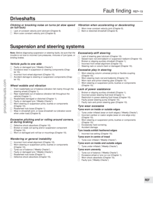 285
285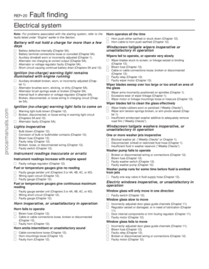 286
286 287
287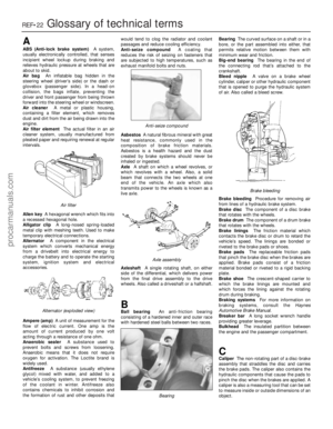 288
288 289
289 290
290 291
291 292
292 293
293 294
294 295
295