Page 105 of 296
3•10 Cooling, heating and ventilation systems
1595Ford Fiesta Remake
Notes
procarmanuals.com
http://vnx.su
Page 106 of 296

4A
1595Ford Fiesta Remake
General
System type . . . . . . . . . . . . . . . . . . . . . . . . . . . . . . . . . . . .\
. . . . . . . . . . Rear-mounted fuel tank, mechanical fuel pump, single Webercarburettor
Carburettor
Type . . . . . . . . . . . . . . . . . . . . . . . . . . . . . . . . . . . .\
. . . . . . . . . . . . . . . . Single or twin choke, downdraught
Application:1.0 litre HCS engines . . . . . . . . . . . . . . . . . . . . . . . . . . . . . . . . . . . .\
. Weber (1V) TLM
1.1 litre HCS engines . . . . . . . . . . . . . . . . . . . . . . . . . . . . . . . . . . . .\
. Weber (2V) TLDM
1.3 HCS engines . . . . . . . . . . . . . . . . . . . . . . . . . . . . . . . . . . . .\
. . . . . Weber (2V) TLDM
1.4 litre CVH engines . . . . . . . . . . . . . . . . . . . . . . . . . . . . . . . . . . . .\
. Weber (2V) DFTM
1.6 litre CVH engines . . . . . . . . . . . . . . . . . . . . . . . . . . . . . . . . . . . .\
. Weber (2V) TLD
Fuel grade
Fuel octane requirement:Engines without catalytic converter* . . . . . . . . . . . . . . . . . . . . . . . . . . 95 RON unleaded or 97 RON leaded
Engines with catalytic converter . . . . . . . . . . . . . . . . . . . . . . . . . . . . . 95 RON unleaded (leaded fuel must notbe used)
*Refer to dealer for latest recommendations
Chapter 4 Part A:
Fuel system - carburettor engines
Accelerator cable (CTX automatic transmission models) -
adjustment . . . . . . . . . . . . . . . . . . . . . . . . . . . . . . . . . . . .\
. . . . . . . 4
Accelerator cable (manual transmission models) - removal, refitting and adjustment . . . . . . . . . . . . . . . . . . . . . . . . . . . . . . . . . . . .\
. . . 3
Accelerator pedal - removal and refitting . . . . . . . . . . . . . . . . . . . . . 5
Accelerator pump diaphragm (Weber TLM carburettor) - removal and refitting . . . . . . . . . . . . . . . . . . . . . . . . . . . . . . . . . . . 16
Air cleaner - removal and refitting . . . . . . . . . . . . . . . . . . . . . . . . . . . 2
Air cleaner element renewal . . . . . . . . . . . . . . . . . . . . . .See Chapter 1
Automatic choke (Weber TLD carburettor) - adjustment . . . . . . . . . 33
Automatic choke (Weber TLD carburettor) - removal, inspection and refitting . . . . . . . . . . . . . . . . . . . . . . . . . . . . . . . . . . . .\
. . . . . . 34
Carburettor (Weber DFTM) - description . . . . . . . . . . . . . . . . . . . . . 25
Carburettor (Weber DFTM) - dismantling, cleaning, inspection and reassembly . . . . . . . . . . . . . . . . . . . . . . . . . . . . . . . . . . . .\
. . . 29
Carburettor (Weber DFTM) - fast-idle speed adjustment . . . . . . . . . 26
Carburettor (Weber DFTM) - removal and refitting . . . . . . . . . . . . . . 28
Carburettor (Weber TLD) - description . . . . . . . . . . . . . . . . . . . . . . . 30
Carburettor (Weber TLD) - dismantling, cleaning, inspection and reassembly . . . . . . . . . . . . . . . . . . . . . . . . . . . . . . . . . . . .\
. . . 36
Carburettor (Weber TLD) - fast-idle speed adjustment . . . . . . . . . . . 31
Carburettor (Weber TLD) - removal and refitting . . . . . . . . . . . . . . . . 35
Carburettor (Weber TLDM) - description . . . . . . . . . . . . . . . .\
. . . . . . 18
Carburettor (Weber TLDM) - dismantling, cleaning, inspection and
reassembly . . . . . . . . . . . . . . . . . . . . . . . . . . . . . . . . . . . .\
. . . . . . 24
Carburettor (Weber TLDM) - fast-idle speed adjustment . . . . . . . . . 19
Carburettor (Weber TLDM) - removal and refitting . . . . . . . . . . . . . . 23
Carburettor (Weber TLM) - description . . . . . . . . . . . . . . . . . . . . . . . 12 Carburettor (Weber TLM) - dismantling, cleaning, inspection and
reassembly . . . . . . . . . . . . . . . . . . . . . . . . . . . . . . . . . . . .\
. . . . . . 17
Carburettor (Weber TLM) - fast-idle speed adjustment . . . . . . . . . . 13
Carburettor (Weber TLM) - removal and refitting . . . . . . . . . . . . . . . 15
Choke cable - removal, refitting and adjustment . . . . . . . . . . . . . . . 6
Fuel gauge sender unit - removal and refitting . . . . . . . . . . . . . . . . . 9
Fuel pump - testing, removal and refitting . . . . . . . . . . . . . . . . . . . . 7
Fuel tank - removal, inspection and refitting . . . . . . . . . . . . . . . . . . . 8
Fuel tank filler pipe - removal and refitting . . . . . . . . . . . . . . . . . . . . 11
Fuel tank ventilation tube - removal and refitting . . . . . . . . . . . . . . . 10
General fuel system checks . . . . . . . . . . . . . . . . . . . . . .See Chapter 1
General information and precautions . . . . . . . . . . . . . . . . . . . . . . . . 1
Idle speed and mixture check and adjustment . . . . . . . .See Chapter 1
Inlet manifold - removal and refitting . . . . . . . . . . . . . . . . . . . . . . . . 37
Needle valve and float (Weber TLD carburettor) -
removal, refitting and adjustment . . . . . . . . . . . . . . . . . . . . . . . . . 32
Needle valve and float (Weber TLDM carburettor) - removal, refitting and adjustment . . . . . . . . . . . . . . . . . . . . . . . . . 20
Needle valve and float (Weber TLM carburettor) - removal, refitting and adjustment . . . . . . . . . . . . . . . . . . . . . . . . . 14
Throttle kicker control solenoid (Weber TLDM carburettor) -
removal and refitting . . . . . . . . . . . . . . . . . . . . . . . . . . . . . . . . . . . 22
Throttle kicker unit (Weber DFTM carburettor) - removal, refitting and adjustment . . . . . . . . . . . . . . . . . . . . . . . . . 27
Throttle kicker unit (Weber TLDM carburettor) - removal, refitting and adjustment . . . . . . . . . . . . . . . . . . . . . . . . . 21
Underbody fuel/brake line check . . . . . . . . . . . . . . . . . . .See\
Chapter 1
Underbonnet check for fluid leaks and hose condition . . .See Chapter 1
4A•1
Specifications Contents
Easy, suitable for
novice with little
experience Fairly easy,
suitable
for beginner with
some experience Fairly difficult,
suitable for competent
DIY mechanic
Difficult,
suitable for
experienced DIY
mechanic Very difficult,
suitable for expert DIY
or professional
Degrees of difficulty
54321
procarmanuals.com
http://vnx.su
Page 107 of 296
 TLM carburettor - 1.0 litre HCS engines")
Fuel pump
Delivery pressure . . . . . . . . . . . . . . . . . . . . . . . . . . . . . . . . . . . .\
. . . . . . 0.24 to 0.38 bars
Carburettor data
Weber (1V) TLM carburettor - 1.0 litre HCS engines
Idle speed and mixture settings . . . . . . . . . . . . . . . . . . . . . . . . . . . . . . . See Chapter 1Fast-idle speed . . . . . . . . . . . . . . . . . . . . . . . . . . . . . . . . . . . .\
. . . . . . . . 3400 ± 100 rpm
Float height . . . . . . . . . . . . . . . . . . . . . . . . . . . . . . . . . . . .\
. . . . . . . . . . . 26.0 ± 1.0 mm
Venturi diameter . . . . . . . . . . . . . . . . . . . . . . . . . . . . . . . . . . . .\
. . . . . . . 23 mm
Main jet . . . . . . . . . . . . . . . . . . . . . . . . . . . . . . . . . . . .\
. . . . . . . . . . . . . . 110
Air correction jet . . . . . . . . . . . . . . . . . . . . . . . . . . . . . . . . . . . .\
. . . . . . . 220
Weber (2V) TLDM carburettor - 1.1 litre HCS engines
Idle speed and mixture settings . . . . . . . . . . . . . . . . . . . . . . . . . . . . . . . See Chapter 1Fast-idle speed:
Manual transmission . . . . . . . . . . . . . . . . . . . . . . . . . . . . . . . . . . . .\
. . 2800 rpm
CTX automatic transmission . . . . . . . . . . . . . . . . . . . . . . . . . . . . . . . . 2600 rpm
Float height . . . . . . . . . . . . . . . . . . . . . . . . . . . . . . . . . . . .\
. . . . . . . . . . . 29.0 ± 1.0 mm
Throttle kicker speed: Manual transmission . . . . . . . . . . . . . . . . . . . . . . . . . . . . . . . . . . . .\
. . 1250 to 1350 rpm
CTX automatic transmission . . . . . . . . . . . . . . . . . . . . . . . . . . . . . . . . 1050 to 1150 rpm
PrimarySecondary
Venturi diameter . . . . . . . . . . . . . . . . . . . . . . . . . . . . . . . . . . . .\
. . . . . . . 26 mm 28 mm
Main jet: Manual transmission . . . . . . . . . . . . . . . . . . . . . . . . . . . . . . . . . . . .\
. . 92122
CTX automatic transmission . . . . . . . . . . . . . . . . . . . . . . . . . . . . . . . . 92112
Emulsion tube . . . . . . . . . . . . . . . . . . . . . . . . . . . . . . . . . . . .\
. . . . . . . . . F113 F75
Air correction jet . . . . . . . . . . . . . . . . . . . . . . . . . . . . . . . . . . . .\
. . . . . . . 195 155
Weber (2V) TLDM carburettor - 1.3 litre HCS engines
Idle speed and mixture settings . . . . . . . . . . . . . . . . . . . . . . . . . . . . . . . See Chapter 1 Fast-idle speed . . . . . . . . . . . . . . . . . . . . . . . . . . . . . . . . . . . .\
. . . . . . . . 2500 rpmFloat height . . . . . . . . . . . . . . . . . . . . . . . . . . . . . . . . . . . .\
. . . . . . . . . . . 29.0 ± 1.0 mm
Throttle kicker speed . . . . . . . . . . . . . . . . . . . . . . . . . . . . . . . . . . . .\
. . . 1900 ± 100 rpm
PrimarySecondary
Venturi diameter . . . . . . . . . . . . . . . . . . . . . . . . . . . . . . . . . . . .\
. . . . . . . 19 mm 20 mm
Main jet . . . . . . . . . . . . . . . . . . . . . . . . . . . . . . . . . . . .\
. . . . . . . . . . . . . . 90122
Emulsion tube . . . . . . . . . . . . . . . . . . . . . . . . . . . . . . . . . . . .\
. . . . . . . . . F113 F75
Air correction jet . . . . . . . . . . . . . . . . . . . . . . . . . . . . . . . . . . . .\
. . . . . . . 185 130
Weber (2V) DFTM carburettor - 1.4 litre CVH engines
Idle speed and mixture settings . . . . . . . . . . . . . . . . . . . . . . . . . . . . . . . See Chapter 1 Fast-idle speed . . . . . . . . . . . . . . . . . . . . . . . . . . . . . . . . . . . .\
. . . . . . . . 2800 ± 100 rpm
Choke pull-down . . . . . . . . . . . . . . . . . . . . . . . . . . . . . . . . . . . .\
. . . . . . 2.7 to 3.2 mm
Float height . . . . . . . . . . . . . . . . . . . . . . . . . . . . . . . . . . . .\
. . . . . . . . . . . 8.0 ± 0.5 mm
Throttle kicker speed:
Manual transmission . . . . . . . . . . . . . . . . . . . . . . . . . . . . . . . . . . . .\
. . 1300 ± 50 rpm
CTX automatic transmission . . . . . . . . . . . . . . . . . . . . . . . . . . . . . . . . 1100 ± 50 rpm (in Neutral)
PrimarySecondary
Venturi diameter . . . . . . . . . . . . . . . . . . . . . . . . . . . . . . . . . . . .\
. . . . . . . 21 mm 23 mm
Main jet . . . . . . . . . . . . . . . . . . . . . . . . . . . . . . . . . . . .\
. . . . . . . . . . . . . . 100 125
Air correction jet . . . . . . . . . . . . . . . . . . . . . . . . . . . . . . . . . . . .\
. . . . . . . 210 155
Emulsion tube . . . . . . . . . . . . . . . . . . . . . . . . . . . . . . . . . . . .\
. . . . . . . . . F22 F60
Idle jet . . . . . . . . . . . . . . . . . . . . . . . . . . . . . . . . . . . .\
. . . . . . . . . . . . . . . 4260
Weber (2V) TLD carburettor - 1.6 litre CVH engines
Idle speed and mixture settings . . . . . . . . . . . . . . . . . . . . . . . . . . . . . . . See Chapter 1 Fast-idle speed . . . . . . . . . . . . . . . . . . . . . . . . . . . . . . . . . . . .\
. . . . . . . . 1800 ± 50 rpm (on third step of fast-idle cam)
Choke pull-down . . . . . . . . . . . . . . . . . . . . . . . . . . . . . . . . . . . .\
. . . . . . 4.7 ± 0.5 mm
Float height . . . . . . . . . . . . . . . . . . . . . . . . . . . . . . . . . . . .\
. . . . . . . . . . . 29.0 ± 0.5 mm
PrimarySecondary
Venturi diameter . . . . . . . . . . . . . . . . . . . . . . . . . . . . . . . . . . . .\
. . . . . . . 2123
Main jet . . . . . . . . . . . . . . . . . . . . . . . . . . . . . . . . . . . .\
. . . . . . . . . . . . . . 117 127
Emulsion tube . . . . . . . . . . . . . . . . . . . . . . . . . . . . . . . . . . . .\
. . . . . . . . . F105 F71
Air correction jet . . . . . . . . . . . . . . . . . . . . . . . . . . . . . . . . . . . .\
. . . . . . . 185 125
Torque wrench settingsNmlbf ft
Fuel pump . . . . . . . . . . . . . . . . . . . . . . . . . . . . . . . . . . . .\
. . . . . . . . . . . . 16 to 20 12 to 15
Inlet manifold . . . . . . . . . . . . . . . . . . . . . . . . . . . . . . . . . . . .\
. . . . . . . . . 16 to 20 12 to 15
4A•2 Fuel system – carburettor engines
1595Ford Fiesta Remakeprocarmanuals.com
http://vnx.su
Page 108 of 296

1 General information andprecautions
General information
The fuel system on all models with
carburettor induction comprises a rear-
mounted fuel tank, a mechanical diaphragm
fuel pump, a carburettor and an air cleaner. The fuel tank is mounted at the rear, under
the floorpan behind the rear seats. The tank
has a “ventilation-to-atmosphere system”
through a combined roll-over/anti-trickle fill
valve assembly, located in the left-hand rear
wheel arch. A filler neck sensing pipe, integral
with the fuel tank filler pipe, will shut off the
petrol pump filler gun when the predetermined
maximum level of fuel is reached in the tank,
so preventing spillage and wastage. A
conventional fuel level sender unit is mounted
in the top face of the fuel tank. One of two fuel pump types will be fitted,
depending on the engine type. On HCS
engines, the fuel pump is operated by a
pivoting rocker arm; one end rests on an
eccentric lobe on the engine camshaft, and
the other end is attached to the fuel pump
diaphragm. The pump fitted to the CVH
engine is operated by a separate pushrod,
one end rests on an eccentric lobe on the
engine camshaft, and the other rests on the
pump actuating rod which operates the
diaphragm. Both types of mechanical pump
incorporate a nylon mesh filter, and are of
sealed type (they cannot be serviced or
overhauled). Four different types of Weber carburettor
are featured in the range, further details being
given in later Sections of this Chapter. The air cleaner incorporates a “waxstat”
controlled air inlet, supplying either hot air
from a shroud mounted around the exhaust
manifold, or cool air from a duct in the front of
the vehicle.
Precautions
Warning: Petrol is extremely
flammable - great care must be
taken when working on any part of the fuel system. Do not smoke or allow
any naked flames or uncovered light bulbs
near the work area. Note that gas powered
domestic appliances with pilot flames,
such as heaters, boilers and tumble
dryers, also present a fire hazard - bear
this in mind if you are working in an area
where such appliances are present.
Always keep a suitable fire extinguisher
close to the work area and familiarise
yourself with its operation before starting
work. Wear eye protection when working
on fuel systems and wash off any fuel spilt
on bare skin immediately with soap and
water. Note that fuel vapour is just as
dangerous as liquid fuel; a vessel that has
just been emptied of liquid fuel will still
contain vapour and can be potentially
explosive. Petrol is a highly dangerous and
volatile liquid, and the precautions
necessary when handling it cannot be
overstressed.
Many of the operations described in this
Chapter involve the disconnection of fuel
lines, which may cause an amount of fuel
spillage. Before commencing work, refer
to the above Warning and the information
in “Safety first” at the beginning of this
manual.
When working with fuel system
components, pay particular attention to
cleanliness - dirt entering the fuel system
may cause blockages which will lead to
poor running.
Certain adjustment points in the fuel system
are protected by tamperproof caps, plugs or
seals. In some territories, it is an offence to
drive a vehicle with broken or missing
tamperproof seals. Before disturbing a
tamperproof seal, first check that no local or
national laws will be broken by doing so, and
fit a new tamperproof seal after adjustment is
complete, where required by law. Do not
break tamperproof seals on any vehicle whilst
it is still under warranty. Carburettors are delicate instruments, and
care must be taken not to disturb any
components unnecessarily. Before attempting
work on a carburettor, ensure that the relevant
spares are available; it should be noted that a complete strip down of a carburettor is
unlikely to cure a fault which is not
immediately obvious, without introducing new
problems. If persistent problems occur, it is
recommended that the services of a Ford
dealer or a carburettor specialist are sought.
Most dealers will be able to provide
carburettor rejetting and servicing facilities.
Where necessary, it may be possible to
purchase a reconditioned carburettor.
2 Air cleaner
-
removal and refitting
1
Note: Air cleaner element renewal and air
cleaner temperature control system checks
are described in Chapter 1.
Removal
1 Disconnect the battery negative (earth) lead
(refer to Chapter 5A, Section 1).
2 On CVH engine models, pull free and
release the accelerator cable from the locating
clip on the side of the air cleaner.
3 Undo the two (HCS engine) or three (CVH
engine) retaining screws, and partially lift the
air cleaner from the carburettor so that the
hose and wiring connections to the underside
of the air cleaner body are accessible (see
illustration) .
4 Note their connections and routings, then
detach the wiring multi-plug and hoses from
the underside of the air cleaner (see
illustrations) . On CVH engines, also
disconnect the vacuum hose from the inlet
manifold.
5 Lift the air cleaner from the carburettor.
6 If required, the inlet air temperature sensor
can be unscrewed and removed from the
base of the air cleaner (where fitted).
Refitting
7 Refit in the reverse order of removal. Renew
any hoses that are perished or cracked, and
ensure that all fittings are securely and
correctly reconnected.
Fuel system – carburettor engines 4A•3
2.4b Disconnecting the intake air temperature sensor multi-plug
(CVH engine shown)2.4a Disconnecting the oil separator/
crankcase ventilation hose from the air
cleaner (CVH engine shown)2.3 Undoing the air cleaner retainingscrews (HCS engine shown)
4A
1595Ford Fiesta Remakeprocarmanuals.com
http://vnx.su
Page 109 of 296
 -
removal, refitting and adjustment
1
Removal
1 Disconnect the battery negative (earth) lead
(refer to Chapter 5A, Section 1).
2 Working inside the vehi")
3Accelerator cable (manual
transmission models) -
removal, refitting and adjustment
1
Removal
1 Disconnect the battery negative (earth) lead
(refer to Chapter 5A, Section 1).
2 Working inside the vehicle, disconnect the
cable from the top of the accelerator pedal,
release the grommet and pull the cable free
from the pedal. Withdraw the cable through
the engine side of the bulkhead.
3 Refer to Section 2 and remove the air
cleaner.
4 Detach the inner cable from the carburettor
linkage.
5 Prise free the retaining clip, detach the
outer cable from the support bracket, and
remove the cable (see illustrations) .
Refitting and adjustment
6To refit the cable, feed the inner cable
through the bulkhead, and reconnect the inner
cable to the accelerator pedal. Note that a
plastic sleeve is supplied with new cables for
the purpose of routing through the bulkhead
panel.
7 Locate the grommet in the bulkhead, then
push the outer cable into it to secure it in the
bulkhead.
8 Lubricate the cable grommet at the
carburettor end with a mild soapy solution, then reconnect the cable to the carburettor.
Locate the outer cable by pulling it towards
the rocker cover.
9
Have an assistant depress the accelerator
pedal fully, and hold it in this position. The
outer cable should be seen to move in its
grommet. Refit the securing clip to the
bracket, then release the accelerator pedal.
10 Depress the accelerator pedal, then
release it and check that the throttle opens
and shuts fully. Further adjust if necessary
before refitting the air cleaner and
reconnecting the battery.
4 Accelerator cable (CTX automatic transmission
models) - adjustment
4
The system for operating the throttle-plate
in the carburettor on CTX automatic
transmission equipped vehicles is completely
different to that employed on manual
transmission vehicles. The cable from the
accelerator pedal leads to a linkage
mechanism which is bolted to the
transmission housing. Two further cables lead
from this linkage mechanism, one of which
operates the throttle-plate in the carburettor. As all three cables have to be adjusted at
the same time, and access to a Ford special
tool is required, it is recommended that a Ford
dealer be entrusted with cable adjustments,
or renewal.
5 Accelerator pedal -
removal and refitting
1
Removal
1 Disconnect the battery negative (earth) lead
(refer to Chapter 5A, Section 1).
2 Peel back the carpet and insulation from
the driver’s footwell to allow access to the
accelerator pedal.
3 Detach the accelerator cable from the pedal
(see Section 3), then release the circlip from
the pivot shaft and remove the accelerator
pedal.
Refitting
4 Refit in the reverse order of removal. On
completion, check the action of the pedal and
the cable to ensure that the throttle has full
unrestricted movement, and fully returns
when released.
5 Reconnect the battery negative lead.
6 Choke cable - removal,
refitting and adjustment
1
Removal
1 Disconnect the battery negative (earth) lead
(refer to Chapter 5A, Section 1).
2 Refer to Section 2 and remove the air
cleaner.
3 Referring to Chapter 10, Section 20, for
further details and illustrations, remove the
choke control knob on the side of the steering
column shroud by pushing in the pin located
on the side of the knob and withdrawing.
4 Detach the steering column lower shroud,
disconnect the multi-plug from the choke
warning light switch/pull control assembly,
and unscrew the collar securing the
switch/pull control assembly to the shroud.
5 Disconnect the choke inner cable from its
location on the carburettor choke linkage,
then release the outer cable retaining clip (see
illustrations) .
6 Push the bulkhead panel grommet through
the bulkhead and remove the cable.
Refitting
7 Route the cable through the bulkhead then
secure the bulkhead panel grommet to its
location.
8 Reconnect the choke inner cable to its
location on the carburettor choke linkage.
9 Refit the choke warning light switch/pull
control assembly to the lower steering column
shroud and secure with the collar, then
reconnect the multi-plug.
10 Refit and secure the lower steering
column shroud, then refit the choke control
knob.
11 Pull the choke control knob to the fully-on
position. Hold the choke in the fully-on
4A•4 Fuel system – carburettor engines
6.5b Choke outer cable retaining clip
released6.5a Disconnect the inner cable from thechoke linkage
3.5b . . . then release from its support bracket3.5a Remove the accelerator outer cablesecuring clip . . .
1595Ford Fiesta Remakeprocarmanuals.com
http://vnx.su
Page 110 of 296

position at the carburettor, then secure the
outer cable with its retaining clip.
Adjustment
12To check that the choke cable is correctly
adjusted, the control knob must be pulled out
to the full-on position and the choke lever
must be in contact with its stop. Adjust as
required if necessary.
13 Press the choke knob fully in (to the off
position), then check that the choke linkage at
the carburettor has fully returned to its off
position and the choke valve plate in the
carburettor is at a right angle (90º) to the
venturi.
14 Refit the air cleaner.
15 Reconnect the battery, turn the ignition
on, operate the choke and check that the
choke warning light operates correctly.
7 Fuel pump -
testing, removal and refitting
2
Note: Refer to the warning note in Section 1
before proceeding.
Testing
1 Access to the fuel pump on HCS engine models is best gained from underneath the
vehicle
(see illustrations) . Apply the
handbrake, then raise and support it on axle
stands at the front end (see “Jacking and
vehicle support” ).
2 The fuel pump may be tested by
disconnecting the fuel feed pipe from the
carburettor, and placing the pipe’s open end
in a suitable container.
3 Detach the multi-plug from the DIS ignition
coil, or the LT lead from the negative terminal
of the ignition coil, to prevent the engine from
firing.
4 Actuate the starter motor. If the fuel pump
is in good working order, regular well-defined
spurts of fuel should eject from the open end
of the disconnected fuel pipe.
5 If this does not occur, and there is fuel in
the tank, the pump is defective and must be
renewed. The fuel pump is a sealed unit, and
cannot be repaired.
Removal
6 Two types of mechanical fuel pump are
fitted, the application depending on the
engine type. Some models may also be fitted
with a fuel vapour separator (see illustration) ;
if this is removed, its hoses should be labelled
to avoid the possibility of confusion and
incorrect attachment on refitting. 7
To remove the fuel pump, first disconnect
the battery negative (earth) lead (refer to
Chapter 5A, Section 1).
8 Where applicable, remove the air cleaner to
improve access to the fuel pump (see Sec-
tion 2).
9 Disconnect the fuel hoses from the fuel
pump, noting their respective connections for
refitting. Where quick-release couplings are
used on the fuel hoses, release the protruding
locking lugs on each union, by squeezing
them together and carefully pulling the
coupling apart. Use rag to soak up any spilt
fuel. Where the unions are colour-coded, the
pipes cannot be confused. Where both unions
are the same colour, note carefully which pipe
is connected to which, and ensure that they
are correctly reconnected on refitting. Plug
the hoses to prevent fuel spillage and the
ingress of dirt.
10 Unscrew and remove the retaining bolts
or nuts (as applicable) and remove the fuel
pump.
11 Recover the gasket/spacer (see
illustration) and if required, withdraw the
pump operating pushrod (CVH engines only).
12 Thoroughly clean the mating faces on the
pump and engine.
Refitting
13 Refit in the reverse order of removal. Be
sure to use a new gasket, and tighten the
securing bolts/nuts securely. Ensure that the
hoses are correctly and securely reconnected.
If they were originally secured with crimped
type hose clips, discard them and fit
screw type clips. Where quick-release
couplings are fitted, press them together until
the locking lugs snap into their groove.
14 When the engine is restarted, check
the pump connections for any signs of fuel
leaks.
8 Fuel tank - removal,
inspection and refitting
3
Note: Refer to the warning note in Section 1
before proceeding.
Removal
1 Run the fuel level as low as possible prior to
removing the tank.
2 Disconnect the battery negative (earth) lead
(refer to Chapter 5A, Section 1).
3 Remove the fuel filler cap, then syphon or
pump out the remaining fuel from the fuel tank
(there is no drain plug). The fuel must be
emptied into a suitable container for storage.
4 Chock the front wheels then jack up the
rear of the car and support it on axle stands
(see “Jacking and vehicle support” ). Remove
the rear roadwheels.
5 Unclip and disconnect the fuel feed and
return hoses located in front of the fuel tank,
and allow any residual fuel to drain into a
Fuel system – carburettor engines 4A•5
7.6 Fuel pump and fuel vapour separator
arrangement on HCS engine (shown from
below)
7.1b Fuel pump assembly fitted to CVHengines (securing nuts arrowed)
A Fuel feed from tank
B Fuel return to tank
C Fuel feed to carburettor7.1a Fuel pump location on HCS engine (shown from below)
A Fuel inlet hose
B Fuel return hose to tank
C Fuel outlet hose to carburettor
D Pump securing bolts
7.11 Gasket/spacer fitment on HCS
engine. Note position of the lug (arrowed)
4A
1595Ford Fiesta Remakeprocarmanuals.com
http://vnx.su
Page 111 of 296
 . Where quick-release couplings
are used on the fuel hoses, release the
protruding locking lugs on each union, by
squeezing them together and carefully")
container which can be sealed (see
illustration) . Where quick-release couplings
are used on the fuel hoses, release the
protruding locking lugs on each union, by
squeezing them together and carefully pulling
the coupling apart. Note that the fuel supply
hose couplings are identified by a white
colour band and the return hose couplings by
a yellow colour band.
6 Disconnect the filler neck sensing pipe
connection from the rear of the tank (see
illustration) .
7 Support beneath the tank to hold it in
position and remove its four securing bolts
(see illustration) .
8 Partially lower the fuel tank and disconnect
the ventilation tube from the tank top surface
and also disconnect the sender unit multi-
plug. The filler pipe should release from its
fuel tank seal location as the tank is
withdrawn.
Inspection
9 Whilst removed, the fuel tank can be
inspected for damage or deterioration.
Removal of the sender unit (see Section 9) will
allow a partial inspection of the interior. If the
tank is contaminated with sediment or water,
swill it out with clean petrol. Do not under any
circumstances undertake any repairs on a
leaking or damaged fuel tank; this work must
be carried out by a professional who has
experience in this critical and potentially-
dangerous work.
10 Whilst the fuel tank is removed from the
vehicle, it should not be placed in an area
where sparks or open flames could ignite the
fumes coming out of the tank. Be especially
careful inside garages where a natural-gas
type appliance is located, because the pilot
light could cause an explosion.
11 Check the condition of the filler pipe seal
in the fuel tank, and renew it if necessary.
Refitting
All models
12 Refitting is a reversal of the removal
procedure. Apply a light smear of grease to the
filler pipe seal, to ease fitting. Ensure that all
connections are securely fitted. Where quick-
release fuel couplings are fitted, press them together until the locking lugs snap into their
groove. If evidence of contamination was
found, do not return any previously-drained
fuel to the tank unless it is carefully filtered first.
9
Fuel gauge sender unit -
removal and refitting
3
Note: Ford specify the use of their service tool
23-014 (a large box spanner with projecting
teeth to engage the fuel gauge sender unit
retaining ring’s slots) for this task. While
alternatives are possible, in view of the difficulty
experienced in removing and refitting the
sender unit, owners are strongly advised to
obtain the correct tool before starting work. The
help of an assistant will be required. Refer to the
warning note in Section 1 before proceeding.
Removal
1 Remove the fuel tank as described in
Section 8.
2 Engage the special tool into the sender unit
then carefully turn the sender unit and release
it from the top of the tank.
Refitting
3 Refit the sender unit in the reverse order of
removal. Be sure to fit a new seal, and
lubricate it with a smear of grease to prevent it
from distorting when fitting the sender unit.
10 Fuel tank ventilation tube -
removal and refitting
3
Note: Refer to the warning note in Section 1
before proceeding.
Removal
1 The fuel tank ventilation tube runs from the
top surface of the fuel tank to the combined roll-
over/anti-trickle-fill valve assembly mounted in
the left-hand rear wheelarch (see illustration).
Its purpose is to eliminate any possibility of
vacuum or pressure build-up in the fuel tank.
2 Disconnect the battery negative (earth) lead
(refer to Chapter 5A, Section 1).
3 Chock the front wheels then jack up the
rear of the car and support it on axle stands
(see “Jacking and vehicle support” ). Remove
the left-hand rear roadwheel.
4 Support the fuel tank from underneath on a
suitable jack, using a large thick sheet of
board to spread the weight, then undo and
remove the four fuel tank securing bolts.
5 Lower the fuel tank slightly in such a manner
so as to allow access to disconnect the
ventilation tube from the tank top surface.
Ensure that the fuel tank does not foul or strain
any adjacent components as it is lowered;
take appropriate action, as necessary.
6 Disconnect the ventilation tube from the
combined roll-over/anti-trickle-fill valve, release
the tube from its retaining clips and remove.
Refitting
7 Refitting is a reversal of the removal
procedure, ensuring that the fuel tank filler
pipe is located correctly with the tank.
11 Fuel tank filler pipe -
removal and refitting
3
Note: Refer to the warning note in Section 1
before proceeding.
Removal
1 Remove the fuel tank as described in
Section 8.
4A•6 Fuel system – carburettor engines
10.1 Combined roll-over anti-trickle-fill valve assembly
A Tube ventilating to atmosphere
B Ventilation tube from fuel tank
8.7 Fuel tank securing bolts (arrowed)8.6 Filler neck sensing pipe connection at the rear of the fuel tank
1595Ford Fiesta Remake
8.5 Fuel feed and return pipe connections
(arrowed)procarmanuals.com
http://vnx.su
Page 112 of 296
 .
3 Disconnect the ventilation tube from the
combined roll-over/anti-trickle-fill valve,
release the ventilation tube from its retaining
clips and d")
2Remove the filler cap surround (see
illustration) .
3 Disconnect the ventilation tube from the
combined roll-over/anti-trickle-fill valve,
release the ventilation tube from its retaining
clips and detach the valve from the vehicle.
4 Remove the filler pipe securing bolt, then
twist and withdraw the filler pipe unit.
5 Prior to refitting, check the condition of the
filler pipe seal in the fuel tank and renew if
necessary.
Refitting
6 Refitting is a reversal of the removal
procedure, but apply a light smear of grease
to the filler pipe seal to aid filler pipe entry.
12 Carburettor (Weber TLM) -
description
The carburettor is of the single (fixed)
venturi downdraught type, featuring a fixed
size main jet system with a mechanically-
operated accelerator pump and vacuum-
operated power valve to provide optimum
fuelling. A manually-operated choke system is
fitted, featuring a vacuum-operated pull-down
mechanism which brings the choke partially
off during conditions of high manifold
vacuum. An anti-dieseling (fuel cut-off) solenoid
(where fitted) prevents the possibility of
engine run-on when the ignition is switched
off. Idle speed and mixture adjustment
procedures are described in Chapter 1, but it
is important to note that accurate adjustments
can only be made using the necessary
equipment.
13 Carburettor (Weber TLM) -
fast-idle speed adjustment
4
Note: Before carrying out any carburettor
adjustments, ensure that the spark plug gaps
are set as specified, and that all electrical and
vacuum connections are secure. To carry out
checks and adjustments, an accurate
tachometer and an exhaust gas analyser (CO
meter) will be required.
1 Check the idle speed and mixture settings
are as specified (as described in Chapter 1).
These must be correct before
checking/adjusting the fast-idle speed.
2 With the engine at its normal operating
temperature, and a tachometer connected in
accordance with the manufacturer’s
instructions, remove the air cleaner (if not
already done) as described in Section 2.
3 Actuate the choke by pulling its control
knob fully out, then start the engine.
4 Hold the choke plate open using a 5.0 mm
twist drill held between the plate and the venturi, and record the fast-idle speed
achieved. If adjustment is necessary, turn the
fast-idle adjusting screw until the specified
speed is obtained
(see illustration).
5 Re-check the fast-idle and basic idle
speeds.
6 On satisfactory completion of the
adjustment, stop the engine, disconnect the
tachometer and CO meter then refit the air
cleaner.
7 Remove the bridging wire from the radiator
cooling fan thermal switch multi-plug, and
reconnect the multi-plug to the thermal
switch.
14 Needle valve and float (Weber
TLM carburettor) - removal,
refitting and adjustment
4
Note: Refer to the warning note in Section 1
before proceeding. New gaskets and a washer
(seal) will be required when reassembling. A
tachometer and an exhaust gas analyser (CO
meter) will also be required to check the idle
speed and mixture settings on completion.
Removal and refitting
1 Disconnect the battery negative (earth) lead
(refer to Chapter 5A, Section 1).
2 Remove the air cleaner as described in
Section 2.
3 Clean the exterior of the carburettor, then
disconnect the fuel feed hose.
4 Disconnect the choke cable and the choke
vacuum hose. 5
Remove the four screws securing the
carburettor upper body (two of these screws
are Torx head type), and detach it. Note that
the carburettor lower body is now loose
on the inlet manifold.
6 Tap out the float retaining pin, remove the
float and withdraw the needle valve. Unscrew
the needle valve housing, as required, noting
washer fitment.
7 Inspect the components for damage and
renew as necessary. Check the needle valve
for wear, and check the float assembly for
leaks by shaking it to see if it contains petrol.
Whilst accessible, clean the float chamber
and jets (refer to Section 17).
8 Using a new washer, refit the needle valve
housing.
9 Refit the needle valve, float and retaining
pin, ensuring that the tag on the float engages
between the ball and clip on the needle valve.
10 Before refitting the carburettor upper
body, check and if necessary adjust the float
level as described in paragraph 15 to 18. Also
check the float and needle valve for full and
free movement.
11 Clean the gasket contact faces (including
the inlet manifold) then, using new gaskets for
the carburettor upper body and the inlet
manifold faces, refit the carburettor upper
body and secure the carburettor assembly to
the inlet manifold.
12 Reconnect the choke vacuum hose. If the
fuel feed hose was originally secured with a
crimped type clip, discard this and secure the
fuel feed hose with a nut and screw type clip.
13 Reconnect and adjust the choke cable,
then refit the air cleaner.
14 Reconnect the battery negative lead, start
and warm up the engine then check the idle
speed and mixture settings as described in
Chapter 1.
Float level adjustment
15 With the carburettor upper body removed
as described in paragraphs 1 to 5 inclusive,
proceed as follows.
16 Hold the carburettor upper body in the
position shown (see illustration) , ensuring
that the needle valve is shut off. Fit the new
upper body gasket to the carburettor upper
Fuel system – carburettor engines 4A•7
13.4 Fast-idle speed adjusting screw (arrowed) (Weber TLM carburettor)
11.2 Removing the filler cap surround
14.16 Float level adjustment (Weber TLM carburettor)
A Adjusting tag
B Float level setting dimension
4A
1595Ford Fiesta Remakeprocarmanuals.com
http://vnx.su
 1
1 2
2 3
3 4
4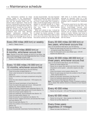 5
5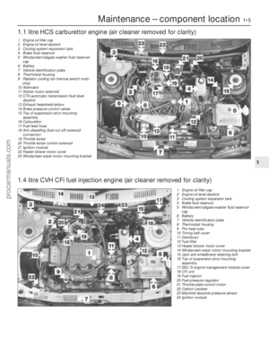 6
6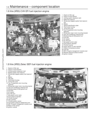 7
7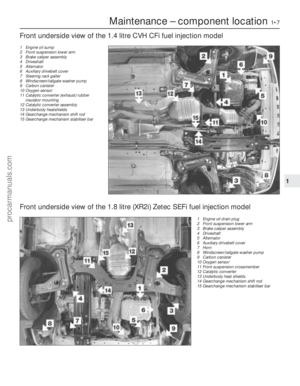 8
8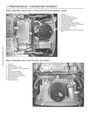 9
9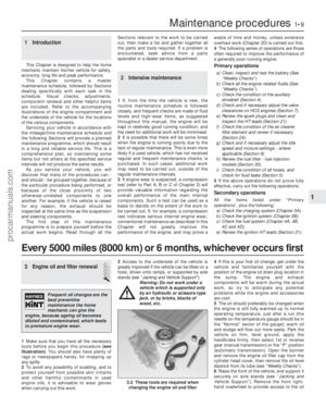 10
10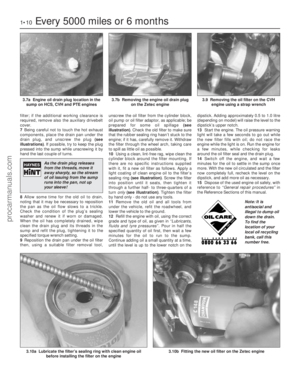 11
11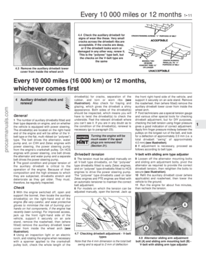 12
12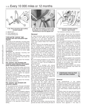 13
13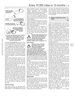 14
14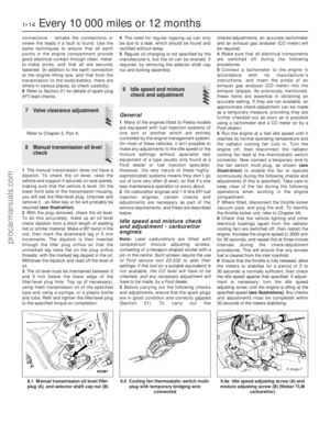 15
15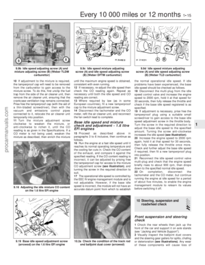 16
16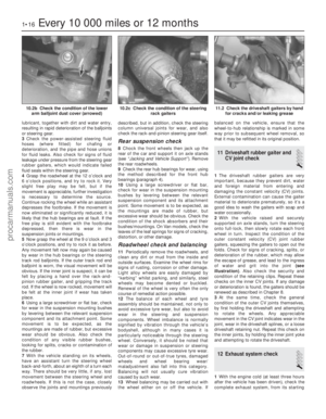 17
17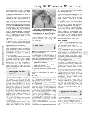 18
18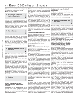 19
19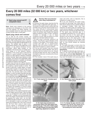 20
20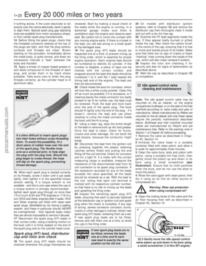 21
21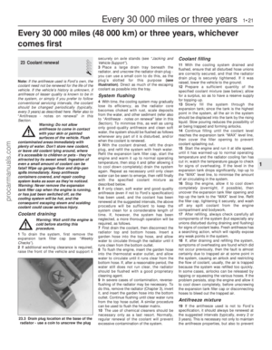 22
22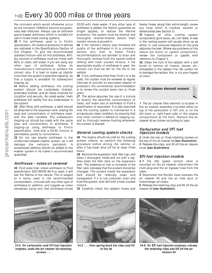 23
23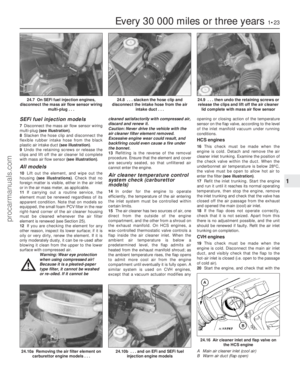 24
24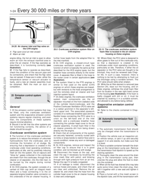 25
25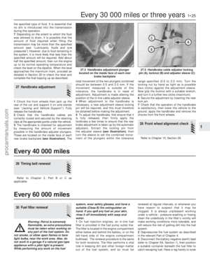 26
26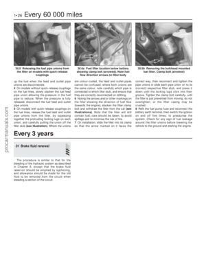 27
27 28
28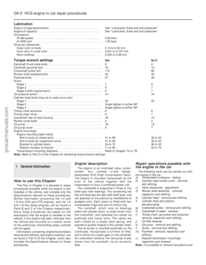 29
29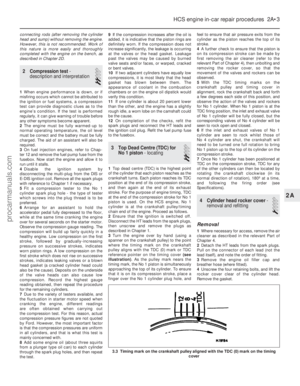 30
30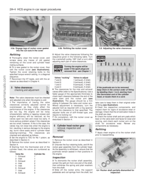 31
31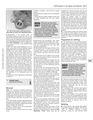 32
32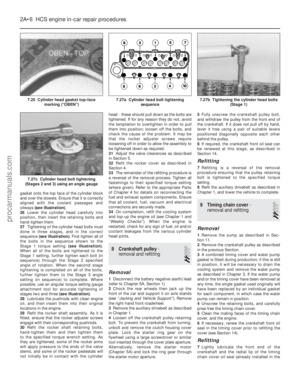 33
33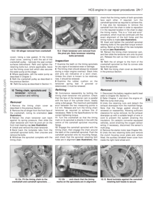 34
34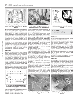 35
35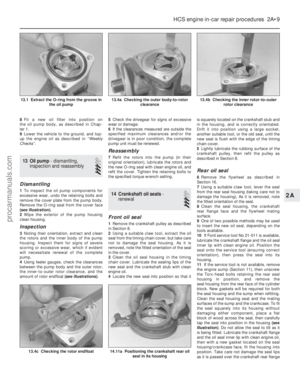 36
36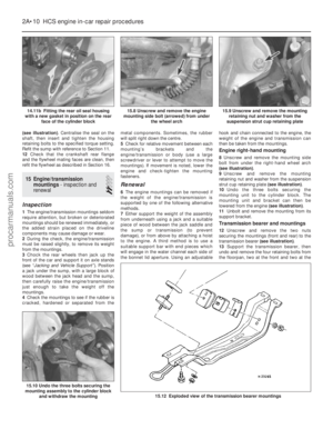 37
37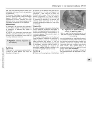 38
38 39
39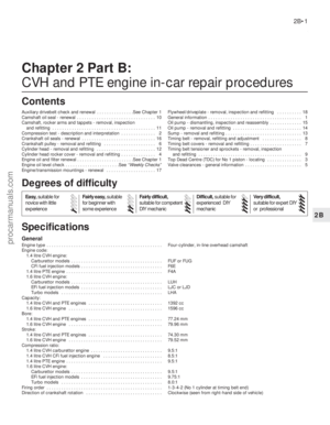 40
40 41
41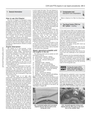 42
42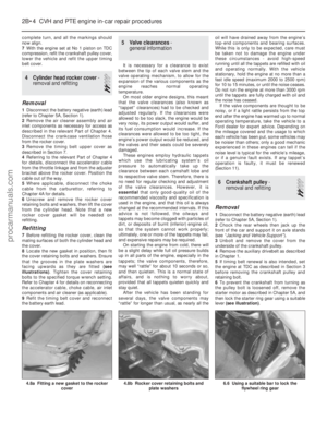 43
43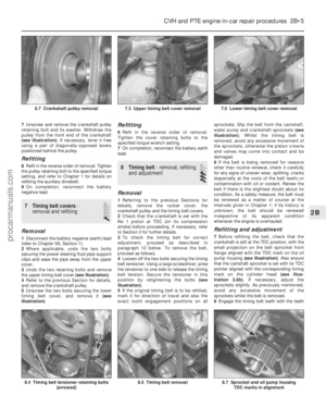 44
44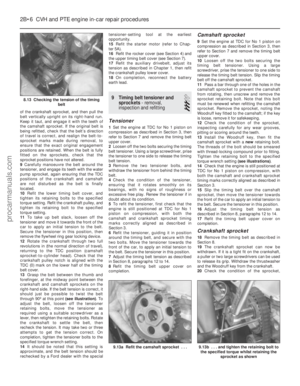 45
45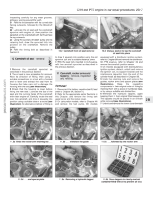 46
46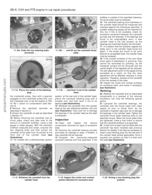 47
47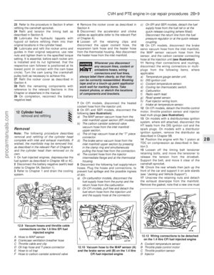 48
48 49
49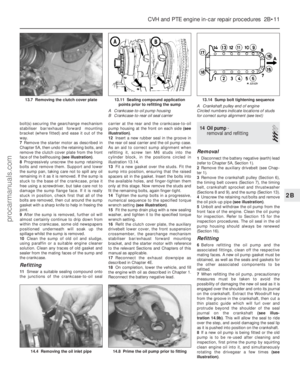 50
50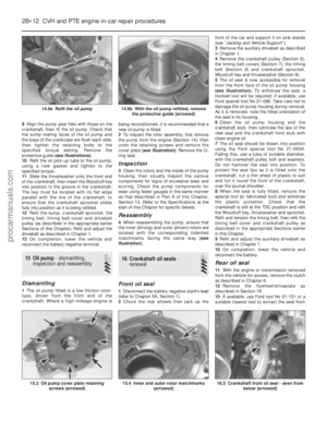 51
51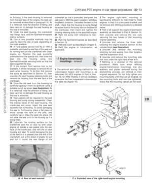 52
52 53
53 54
54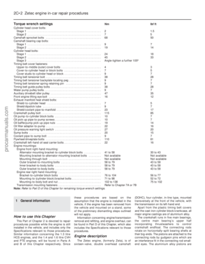 55
55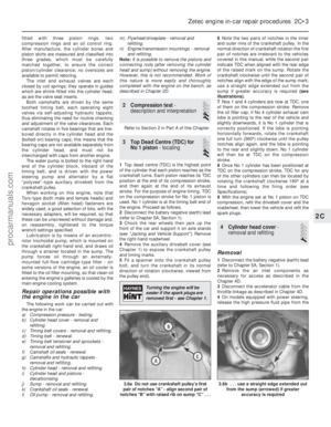 56
56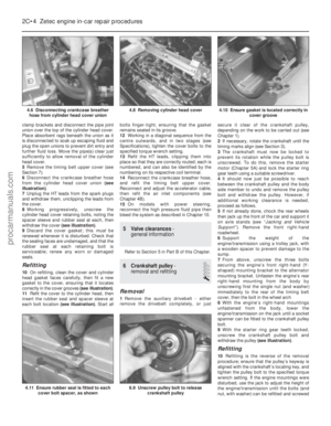 57
57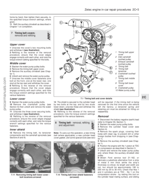 58
58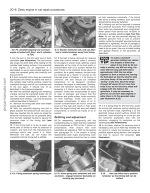 59
59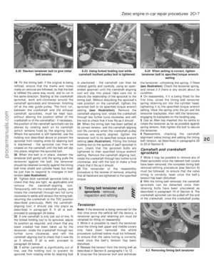 60
60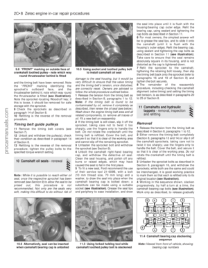 61
61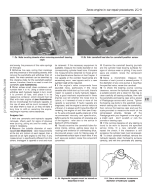 62
62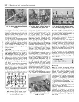 63
63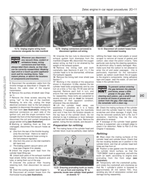 64
64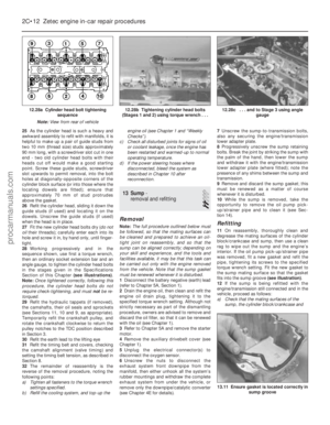 65
65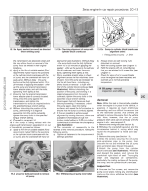 66
66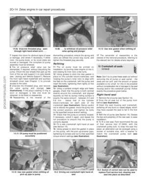 67
67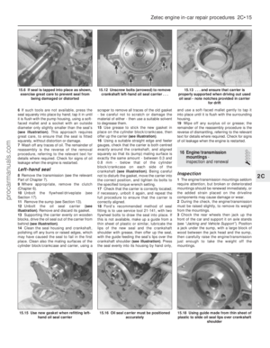 68
68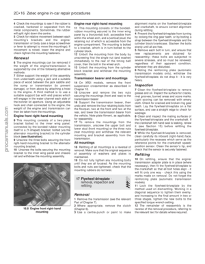 69
69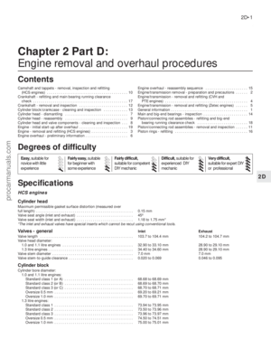 70
70 71
71 72
72 73
73 74
74 75
75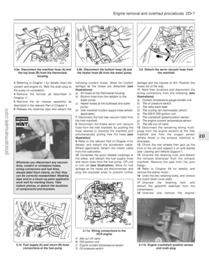 76
76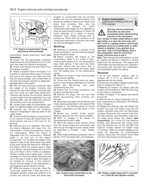 77
77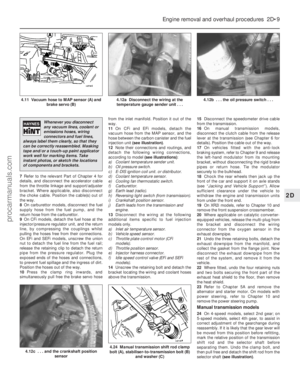 78
78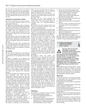 79
79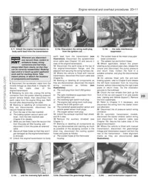 80
80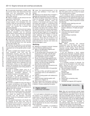 81
81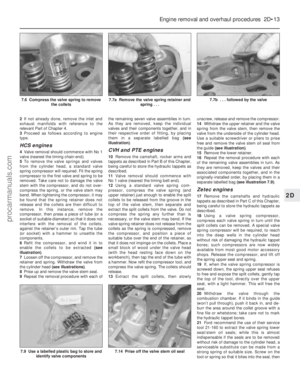 82
82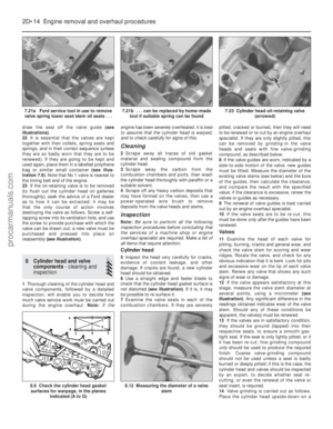 83
83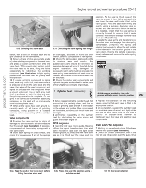 84
84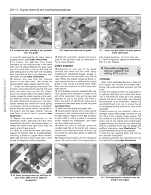 85
85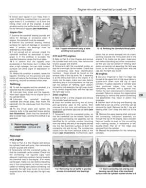 86
86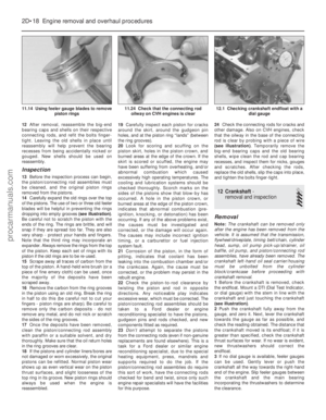 87
87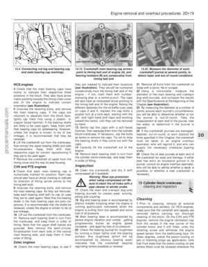 88
88 89
89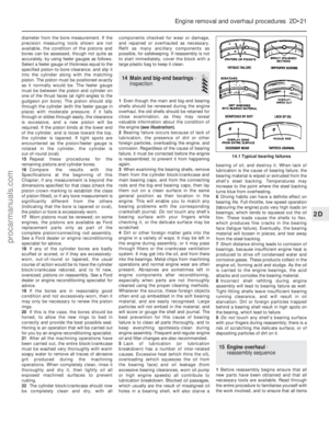 90
90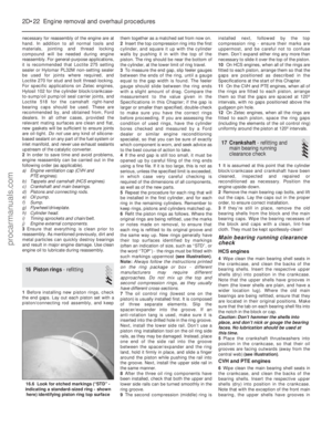 91
91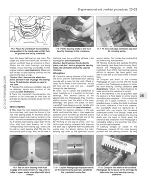 92
92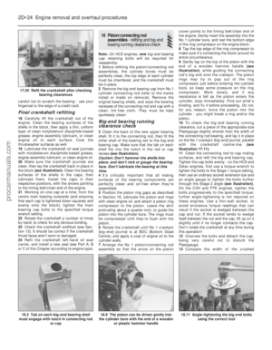 93
93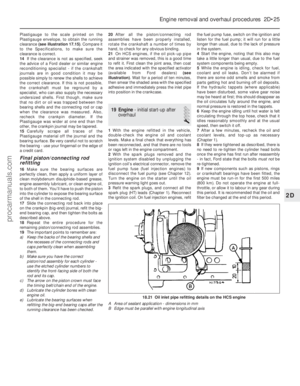 94
94 95
95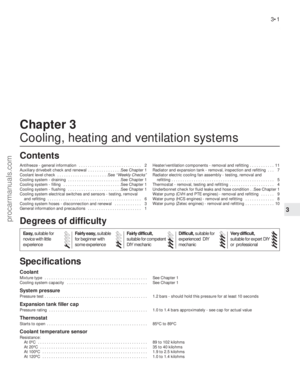 96
96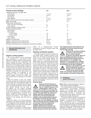 97
97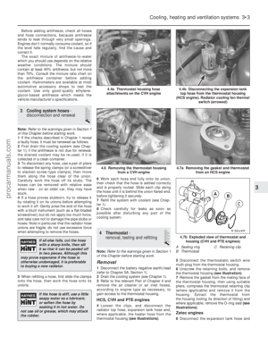 98
98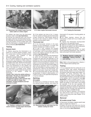 99
99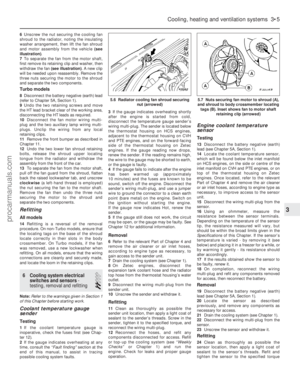 100
100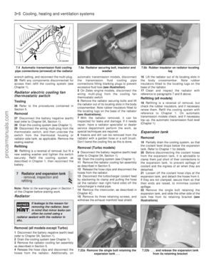 101
101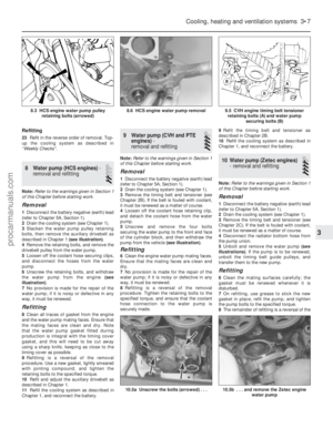 102
102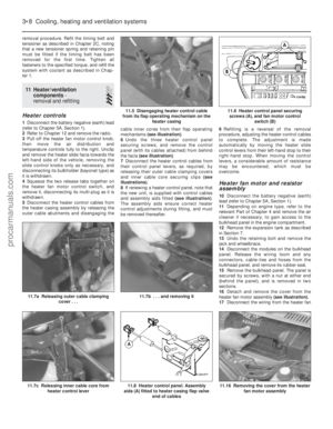 103
103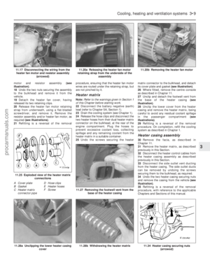 104
104 105
105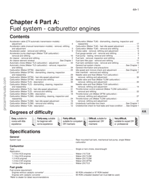 106
106 107
107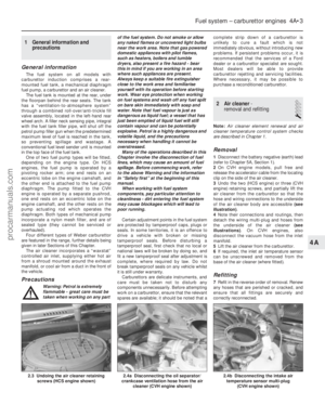 108
108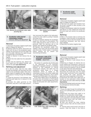 109
109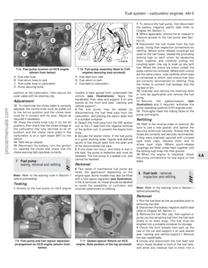 110
110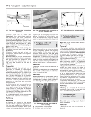 111
111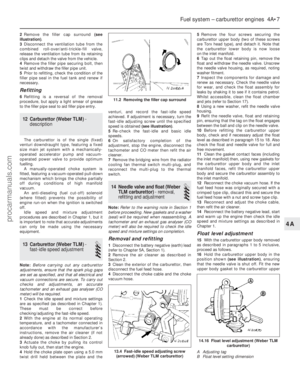 112
112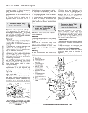 113
113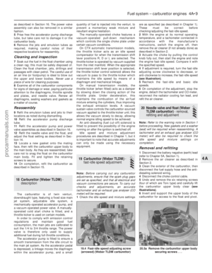 114
114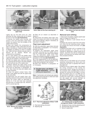 115
115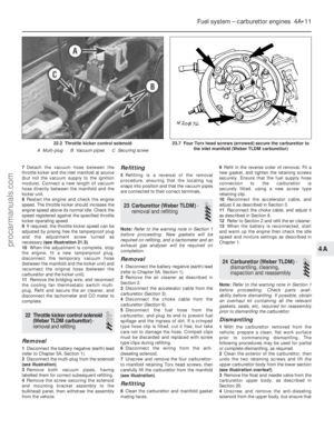 116
116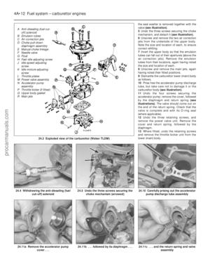 117
117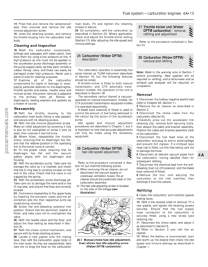 118
118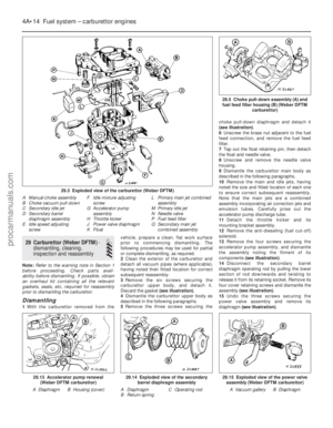 119
119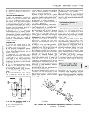 120
120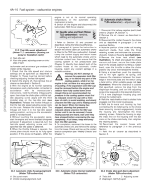 121
121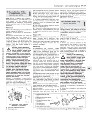 122
122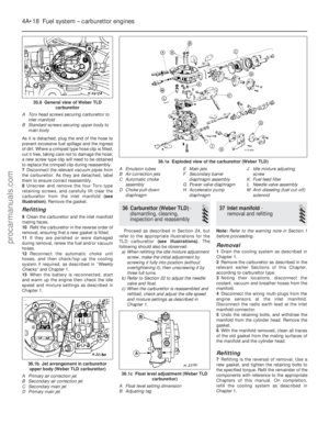 123
123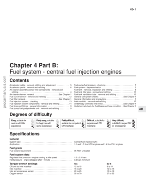 124
124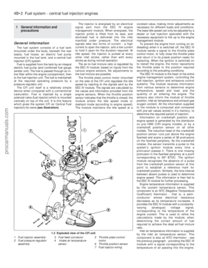 125
125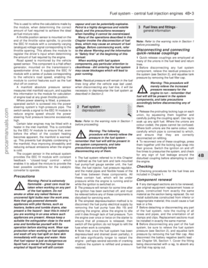 126
126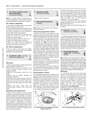 127
127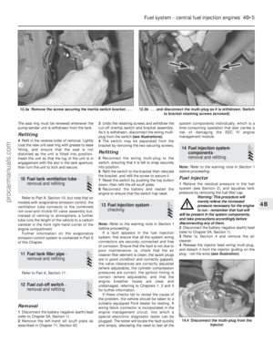 128
128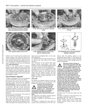 129
129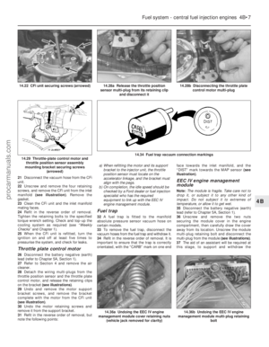 130
130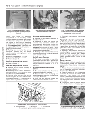 131
131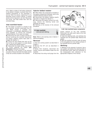 132
132 133
133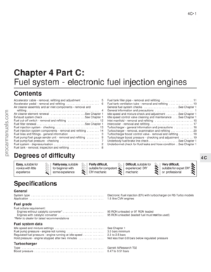 134
134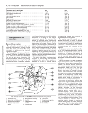 135
135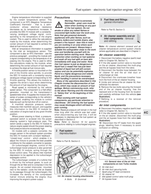 136
136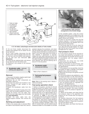 137
137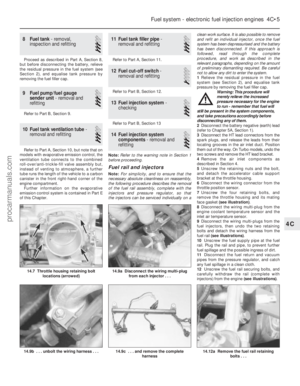 138
138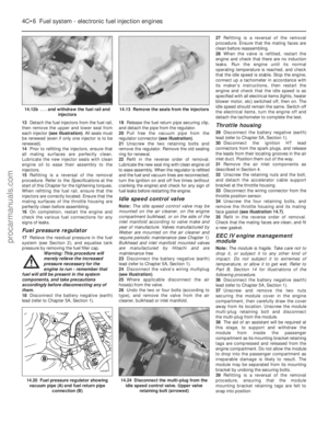 139
139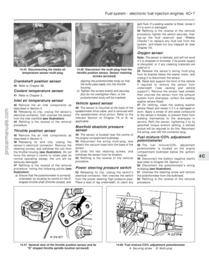 140
140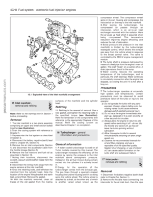 141
141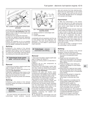 142
142 143
143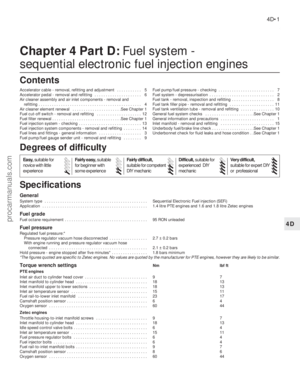 144
144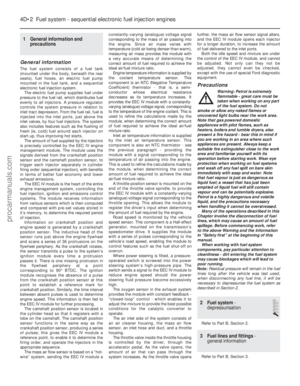 145
145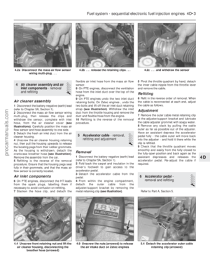 146
146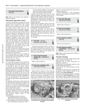 147
147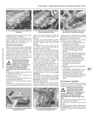 148
148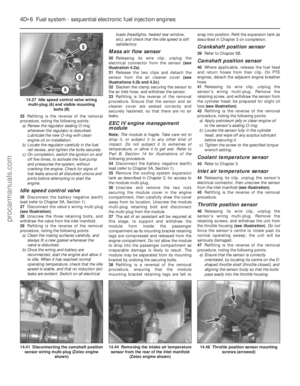 149
149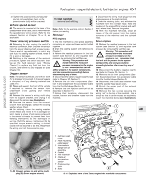 150
150 151
151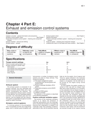 152
152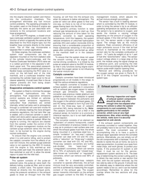 153
153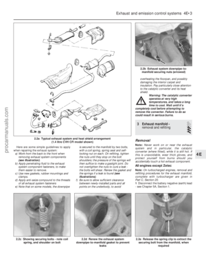 154
154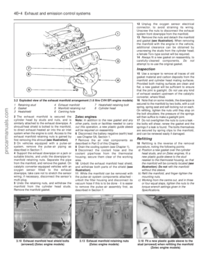 155
155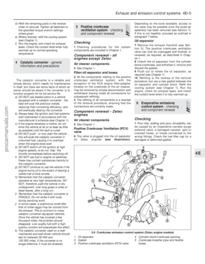 156
156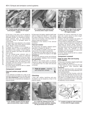 157
157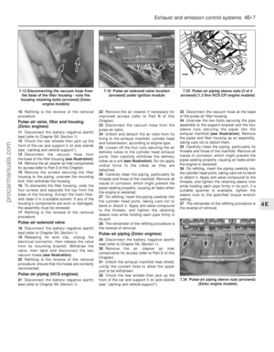 158
158 159
159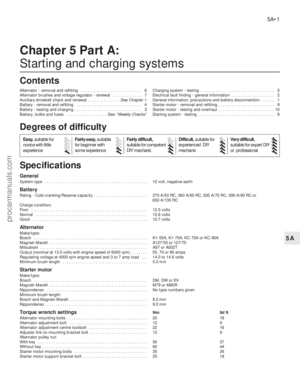 160
160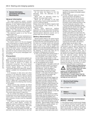 161
161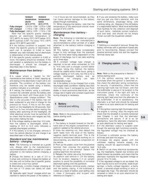 162
162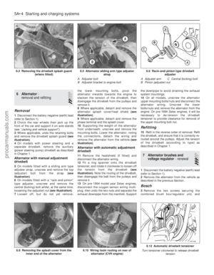 163
163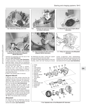 164
164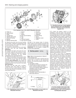 165
165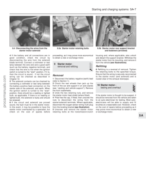 166
166 167
167 168
168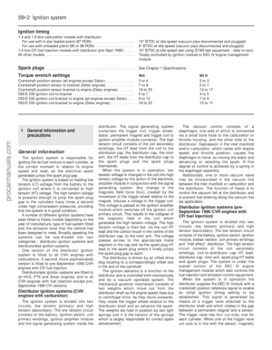 169
169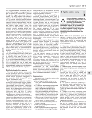 170
170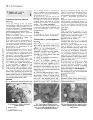 171
171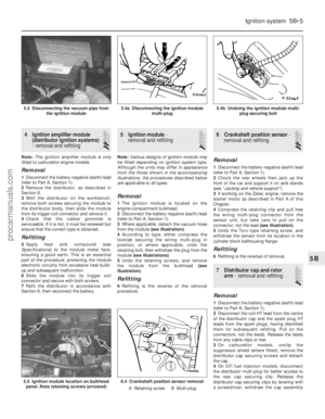 172
172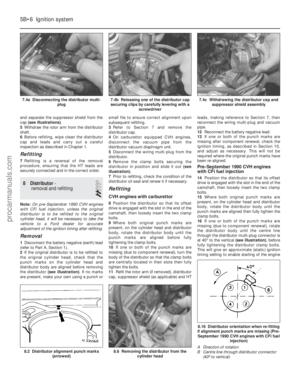 173
173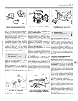 174
174 175
175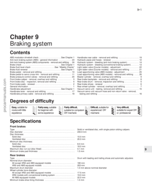 176
176 177
177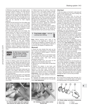 178
178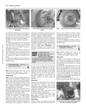 179
179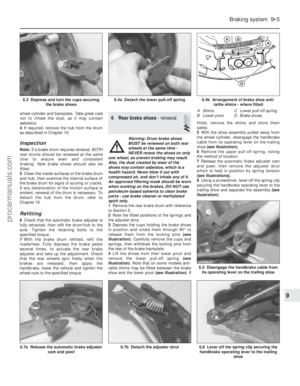 180
180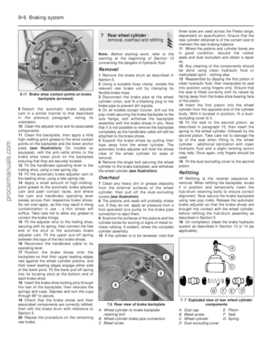 181
181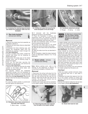 182
182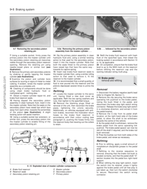 183
183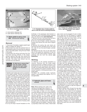 184
184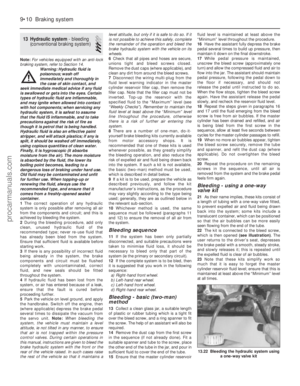 185
185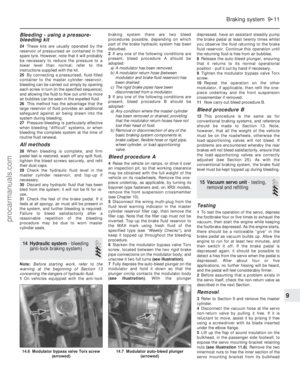 186
186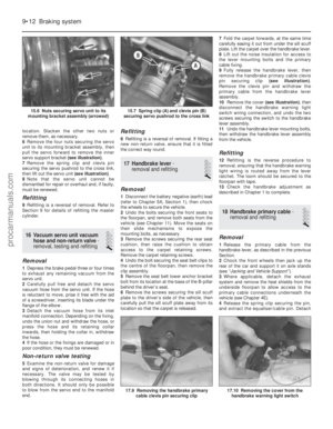 187
187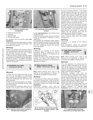 188
188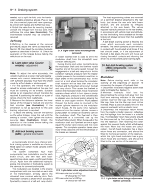 189
189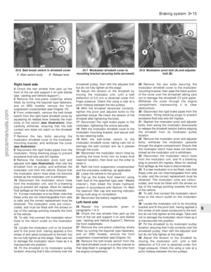 190
190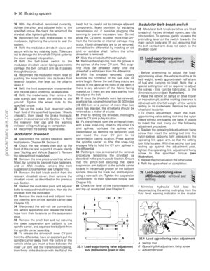 191
191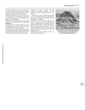 192
192 193
193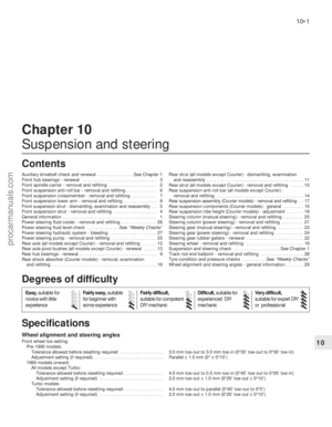 194
194 195
195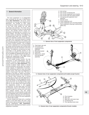 196
196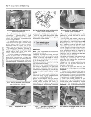 197
197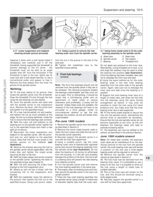 198
198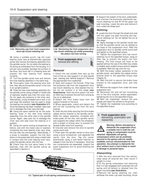 199
199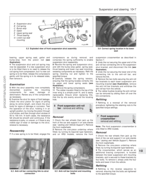 200
200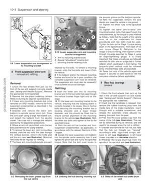 201
201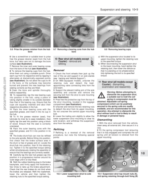 202
202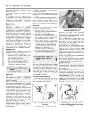 203
203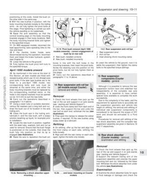 204
204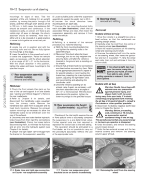 205
205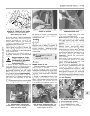 206
206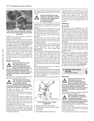 207
207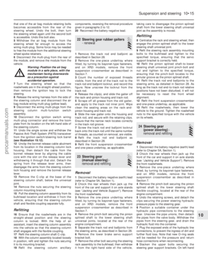 208
208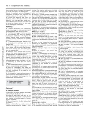 209
209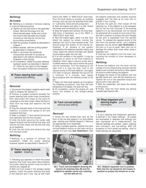 210
210 211
211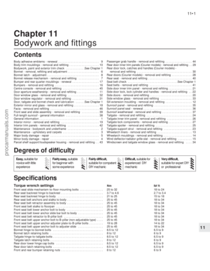 212
212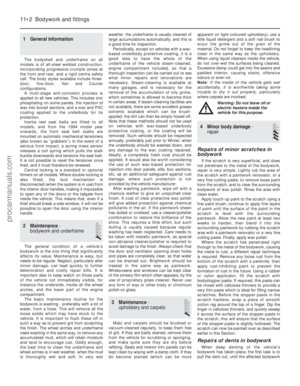 213
213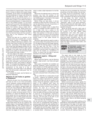 214
214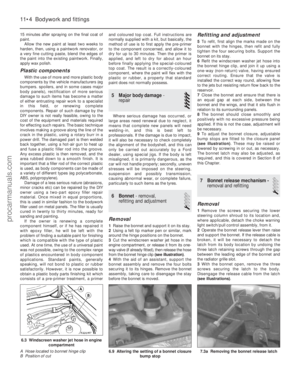 215
215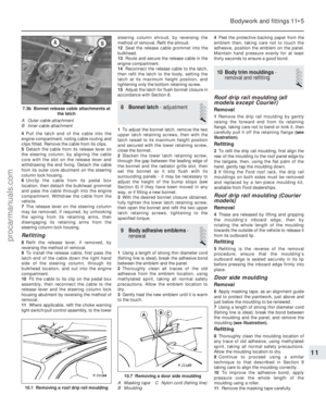 216
216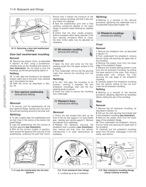 217
217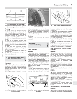 218
218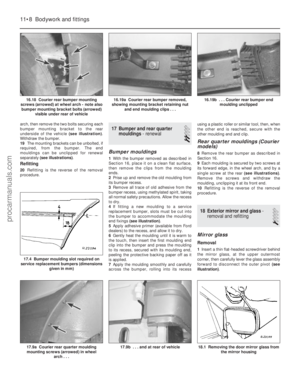 219
219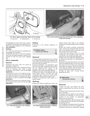 220
220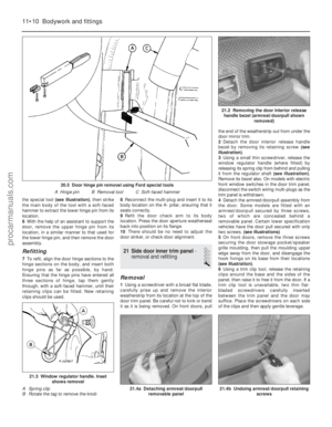 221
221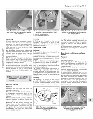 222
222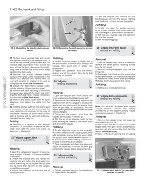 223
223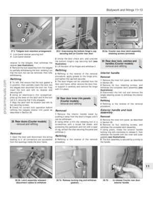 224
224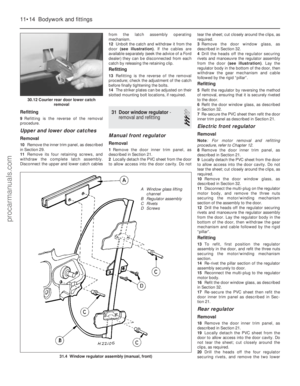 225
225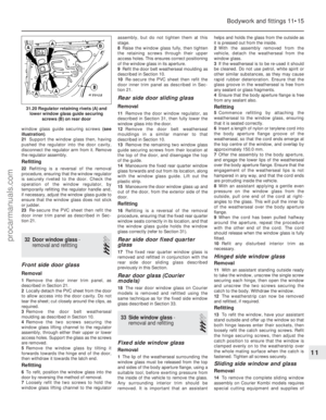 226
226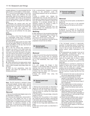 227
227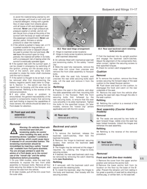 228
228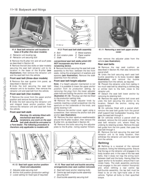 229
229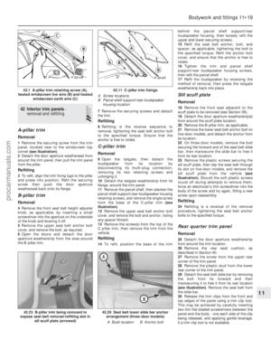 230
230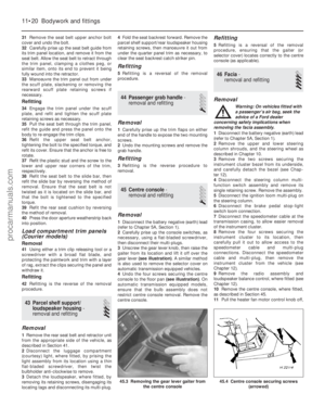 231
231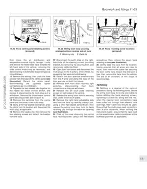 232
232 233
233 234
234 235
235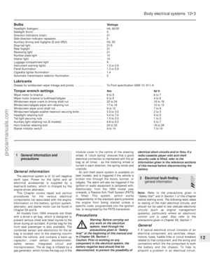 236
236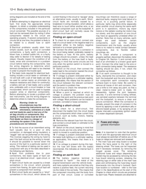 237
237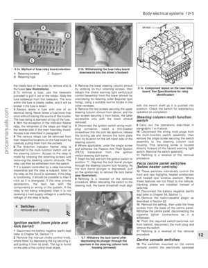 238
238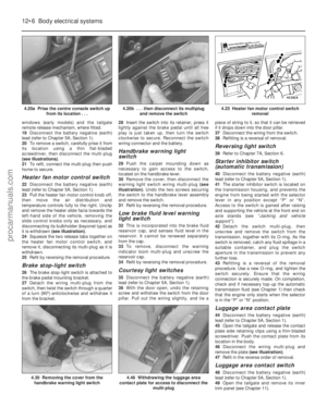 239
239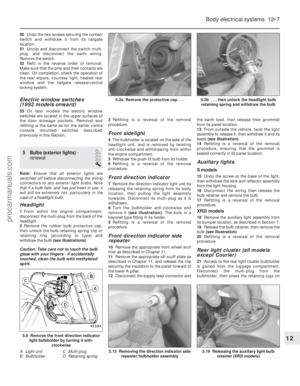 240
240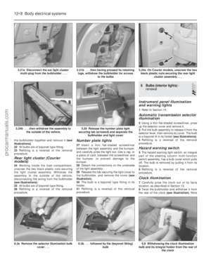 241
241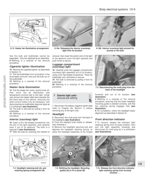 242
242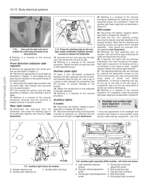 243
243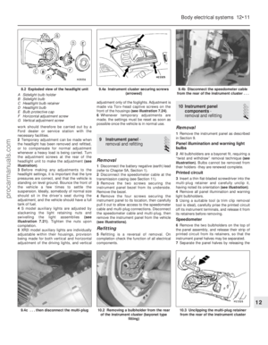 244
244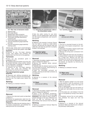 245
245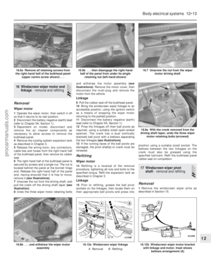 246
246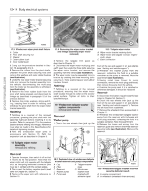 247
247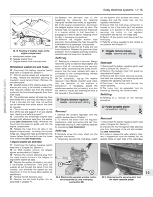 248
248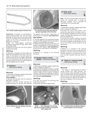 249
249 250
250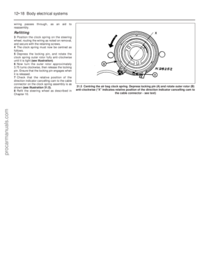 251
251 252
252 253
253 254
254 255
255 256
256 257
257 258
258 259
259 260
260 261
261 262
262 263
263 264
264 265
265 266
266 267
267 268
268 269
269 270
270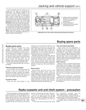 271
271 272
272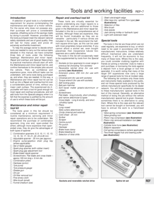 273
273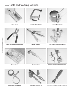 274
274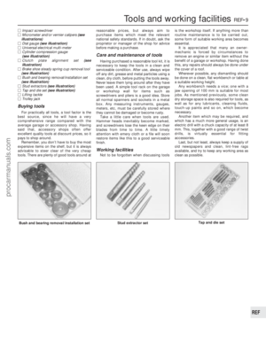 275
275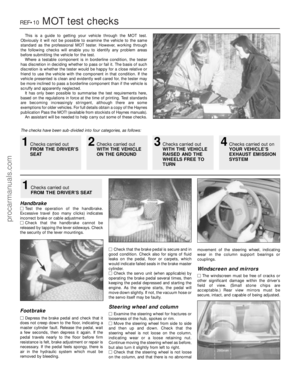 276
276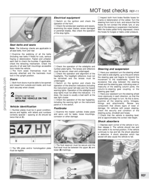 277
277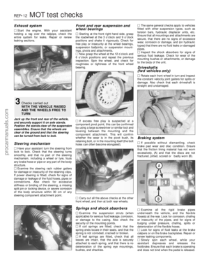 278
278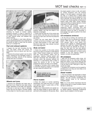 279
279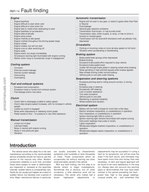 280
280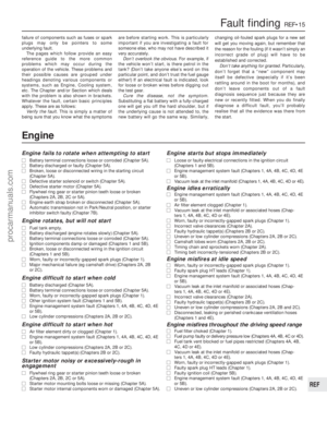 281
281 282
282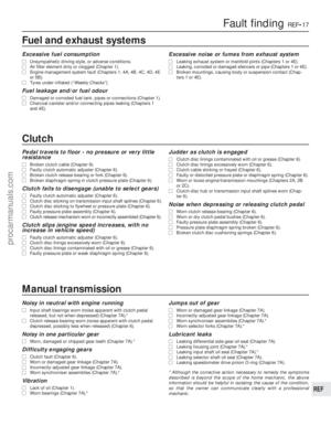 283
283 284
284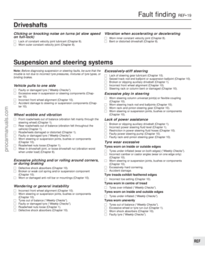 285
285 286
286 287
287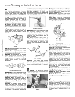 288
288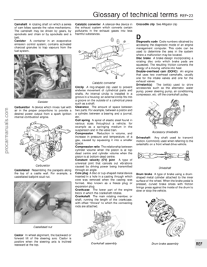 289
289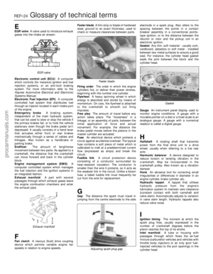 290
290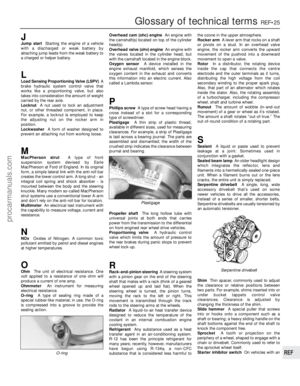 291
291 292
292 293
293 294
294 295
295