Page 217 of 296
 . Do not ben")
Door belt weatherseal moulding
Removal
12Remove the exterior mirror, as described
in Section 18 then, using a screwdriver,
carefully prise up the moulding and remove it
(see illustration) . Do not bend or kink the
moulding, as this will permanently deform it.
Refitting
13 To refit, align the moulding to its rearward
location (latch end of the door), then carefully
tap it into position by hand.
14 Refit the mirror as described in Sec-
tion 18.
11 Door aperture weatherstrip -
removal and refitting
1
Removal
1 To remove, pull the weatherstrip off the
door aperture flange, starting with one end of
the joint and working around to the other end.
Refitting
2 To refit, roughly align the weatherstrip joint
so that it lies in the centre of the bottom (sill
panel) flange.
3 Loop the weatherstrip into the corners of
the door aperture (see illustration).
4 With all the corners roughly in position,
work around the aperture from one end of the
weatherstrip, pressing the seal fully home. Ensure that it follows the contours of the
corners without wrinkling, and that it sits over
any interior trim edgings.
5
Seal the weatherstrip joint with a little
caulking compound applied to the body
flange, to prevent water entering by capillary
action.
6 Check that the door closes properly,
without excessive effort being required. If the
door requires excessive effort to close,
the door striker plate may be adjusted as
necessary.
12 Sill extension moulding -
removal and refitting
2
Removal
1 Open the door and prise out the four
retaining studs from the upper surface of the
moulding.
2 From underneath, drill out the five securing
rivets then remove the moulding from the
vehicle.
Refitting
3 To refit, first align the moulding to its
location, centring it between the two
wheelarch mouldings, then refit the four
retaining studs to secure.
4 Insert the rivets to secure the moulding
from underneath.
13 Wheelarch liners -
removal and refitting
1
Removal
1 Chock the rear wheels then jack up the
front of the car and support it on axle stands
(see “Jacking and vehicle support” ). Remove
the relevant front roadwheel.
2 Release the fasteners securing the
wheelarch liner in position (see illustration),
then remove the liner from the vehicle,
manoeuvring it to clear obstructions as
necessary.
Refitting
3 Refitting is a reversal of the removal
procedure, tightening the roadwheel nuts to
the specified torque (see Chapter 10).
14 Wheelarch mouldings -
removal and refitting
2
Front
Removal
1 Remove the wheelarch liner, as described
in Section 13.
2 From underneath the wheelarch, remove
the four fixing nuts securing the upper part of
the moulding.
3 Remove the plastic stud from the lower
edge of the wheelarch flange.
4 Remove the forward jacking position cover
from the sill extension moulding, by pulling
the lower section of the cover, then using a
suitably-sized drill, remove the rivet
securing the rear edge of the wheelarch
moulding.
5 Carefully detach the wheelarch moulding
from the vehicle, sliding its rear out from
under the sill extension moulding.
Refitting
6 Refitting is a reversal of the removal
procedure, adjusting alignment as necessary
before riveting the rear of the moulding.
Rear
Removal
7 Remove the sill extension moulding, as
described in Section 12.
8 Drill out the rivet securing the forward end
of the wheelarch moulding (see illustration).
9 Remove the plastic stud from the lower
edge of the wheelarch flange.
10 From underneath the wheelarch, remove
the four fixing nuts securing the upper part of
the moulding.
11 Carefully pull the wheelarch moulding
away from the body, disengage it from the
clamp, and remove.
11•6 Bodywork and fittings
14.8 Rear wheelarch moulding fixings (clamp cutaway arrowed)13.2 Front wheelarch liner fixings
A Locating lug at top of wheelarch11.3 Loop the weatherstrip into the door aperture
10.12 Removing a door belt weathersealmoulding
1595Ford Fiesta Remakeprocarmanuals.com
http://vnx.su
Page 218 of 296

Refitting
12To refit, engage the wheelarch moulding
into the clamp, align the moulding studs with
their wheelarch locations, then position the
moulding onto the wheelarch. Refit the four
fixing nuts to secure the upper part of the
moulding, but do not fully tighten.
13 Refit the plastic stud, but do not fully
tighten.
14 Offer the sill extension moulding to its
location, centring it between the front and rear
wheelarches to check the rear wheelarch
moulding alignment. Adjust the alignment as
necessary.
15 With the rear wheelarch moulding
alignment correct, fully tighten the fixing nuts
and the plastic stud.
16 Insert the rivet to secure the forward end
of the moulding.
17 Refit the sill extension moulding, as
described in Section 12.
15 Wind deflector/radiator grille slat - removal and refitting
1
Removal
1The radiator grille slat is secured to the front
bumper by three clips. To remove it, simply
slide the clips rearwards to release them, then
withdraw the grille slat from its bumper
locating holes.
2 If fitting a radiator grille slat to a service replacement bumper, two 8.0 mm diameter
holes will need to be drilled to accommodate
the grille slat end fixings and, in addition, a
12.0 mm square central hole must also be
made
(see illustration) .
Refitting
3Refitting is a reversal of the removal
procedure.
16 Bumpers -
removal and refitting
2
Front bumper
Removal
1 Open the bonnet and disconnect the
auxiliary light multi-plugs, as applicable.
2 Remove the bumper retaining screws from
the leading edge of the wheelarch flanges,
then ease the bumper away from its
wheelarch location (see illustration).
3 Remove the bumper retaining nuts from the
reverse side of the body panel beneath the
headlights (see illustration) then, with the
help of an assistant, remove the bumper
assembly from the vehicle.
Refitting
4 To refit, (again with assistance) position the
bumper onto its panel, ensuring that the
retaining studs pass through their body locations, and that its ends align to the
wheelarches.
5
Loosely refit the bumper retaining nuts and
the bumper-to-wheelarch retaining screws.
6 Ensuring that the bumper is level, and that
an even gap is maintained between it and
surrounding body panels, tighten the retaining
nuts to the specified torque.
7 Tighten the bumper to wheelarch retaining
screws.
8 Refit the auxiliary light multi-plugs, as
applicable.
9 The alignment of light units requires the use
of optical beam setting equipment so, where
applicable, entrust this task to a Ford dealer.
Rear bumper (all models except
Courier)
Removal
10 Using a screwdriver or similar tool, prise
up the number plate light unit from the
rear bumper, being careful not to damage the
bumper. Disconnect the bulbholder and
remove from the bumper.
11 Remove the bumper-to-wheelarch
retaining screws as necessary (see
illustration) .
12 Open the tailgate then, using a suitably-
sized socket, remove the bumper retaining
nuts located inside the luggage compartment
(see illustration) .
13 Carefully remove the bumper from its
location.
Refitting
14 To refit, first align the bumper to the
vehicle body, ensuring that the ends engage
correctly at the wheelarches and the securing
studs enter through the body panel.
15 Refit the bumper-to-wheelarch inner rim
retaining screws, as applicable.
16 Refit the bumper retaining nuts, tightening
to the specified torque.
17 Reconnect the number plate light
bulbholder, then refit the light unit to the
bumper.
Rear bumper (Courier models)
Removal
18 Unscrew the two screws securing each
bumper end moulding to its respective wheel
Bodywork and fittings 11•7
16.2 Front bumper-to-wheelarch retaining screws (arrowed)15.2 Radiator grille slot fixing holes
required on service replacement bumpers (dimensions given in mm - see text)
16.12 Rear bumper retaining nut locations (arrowed)16.11 Rear bumper-to-wheelarch retainingscrews (arrowed)
16.3 Front bumper retaining nut location
11
1595Ford Fiesta Remakeprocarmanuals.com
http://vnx.su
Page 219 of 296
.
Withdraw the bumper.
19 The mounting brackets can be unbolted, if
require")
arch, then remove the two bolts securing each
bumper mounting bracket to the rear
underside of the vehicle (see illustration).
Withdraw the bumper.
19 The mounting brackets can be unbolted, if
required, from the bumper. The end
mouldings can be unclipped for renewal
separately (see illustrations) .
Refitting
20Refitting is the reverse of the removal
procedure.
17 Bumper and rear quarter
mouldings - renewal
2
Bumper mouldings
1With the bumper removed as described in
Section 16, place it on a clean flat surface,
then remove the clips from the moulding
ends.
2 Prise up and remove the old moulding from
its bumper recess.
3 Remove all trace of old adhesive from the
bumper recess, using methylated spirit, taking
all normal safety precautions. Allow the recess
to dry.
4 If fitting a new moulding to a service
replacement bumper, slots must be cut into
the bumper to accommodate the moulding
end fixings (see illustration) .
5 Apply adhesive primer (available from Ford
dealers) to the recess, and allow it to dry.
6 Gently heat the moulding until it is warm to
the touch, then insert the first moulding end
clip into the bumper and press the moulding
to its recess, secured with its moulding end,
peeling the protective backing paper off as it
is applied.
7 Apply the moulding smoothly and carefully
across the bumper, rolling into its recess using a plastic roller or similar tool, then, when
the other end is reached, secure with the
other moulding end and clip.
Rear quarter mouldings (Courier
models)
8
Remove the rear bumper as described in
Section 16.
9 Each moulding is secured by two screws at
its forward edge, in the wheel arch, and by a
single screw at the rear (see illustrations).
Remove the screws and withdraw the
moulding, unclipping it at its front end.
10 Refitting is the reverse of the removal
procedure.
18 Exterior mirror and glass -
removal and refitting
1
Mirror glass
Removal
1 Insert a thin flat-headed screwdriver behind
the mirror glass, at the upper outermost
corner, then carefully lever the glass assembly
forward to disconnect the outer pivot (see
illustration) .
11•8Bodywork and fittings
18.1 Removing the door mirror glass from
the mirror housing17.9b . . . and at rear of vehicle17.9a Courier rear quarter mouldingmounting screws (arrowed) in wheel
arch . . .
17.4 Bumper moulding slot required on
service replacement bumpers (dimensions given in mm)
16.19b . . . Courier rear bumper endmoulding unclipped16.19a Courier rear bumper removed,
showing mounting bracket retaining nut and end moulding clips . . .16.18 Courier rear bumper mounting
screws (arrowed) at wheel arch - note also bumper mounting bracket bolts (arrowed) visible under rear of vehicle
1595Ford Fiesta Remakeprocarmanuals.com
http://vnx.su
Page 220 of 296
 .
Refitting
3To refit, first reconnect the operating")
2Disengage the inner pivot then, using a
screwdriver, disconnect the operating link to
allow the glass assembly to be withdrawn
(see illustration) .
Refitting
3To refit, first reconnect the operating link
and engage the inner pivot.
4 Align the outer pivot in the mirror housing,
then push the glass assembly carefully into
position so that the outer pivot engages
fully.
Mirror assembly
Removal
5 Remove the door inner trim panel as
described in Section 21.
6 Remove the door mirror operating knob by
lifting its retaining clip, using a small
screwdriver, then pulling it from its shaft (see
illustration) .
7 Remove the mirror trim retaining screw,
then ease the mirror trim out from its forward
lug location and slide it out towards the rear of
the vehicle, to clear its rearward fixings (see
illustration) .
8 Remove the three mirror retaining screws,
and manoeuvre the mirror from the door (see
illustration) .
Refitting
9Refitting is the reverse sequence to
removal.
19 Interior mirror -
removal and refitting
1
Removal
1 Using a length of strong thin cord or fishing
line, break the adhesive bond between the
mirror base and the windscreen, then remove
the mirror from the vehicle.
2 During installation, it is important to note
that the mirror base, windscreen black patch
and the adhesive patch should not be
touched, other than for cleaning, or the
adhesive bond may be adversely affected.
3 Remove all traces of old adhesive from the
mirror base, using a lint-free cloth and
methylated spirit, taking all normal safety
precautions. Allow the mirror base to dry.
4 Clean the windscreen black patch in a
similar manner.
Refitting
5 Note that, before installing the mirror, the vehicle should have been in an ambient
temperature of approximately 20ºC for at least
an hour.
6
With the contact surfaces scrupulously
clean, remove the protective tape from one
side of the adhesive patch and press firmly
into contact with the mirror base.
7 Note that when fitting a mirror to a new
windscreen, the protective tape must be
removed from the windscreen black patch.
8 Warm the mirror base and adhesive patch
for about thirty seconds, to a temperature of
50 to 70ºC.
9 Remove the protective tape from the other
side of the adhesive patch on the mirror base,
then align the mirror base and windscreen
black patch accurately, and firmly press the
mirror base into position. Hold the mirror base
firmly in position for at least two minutes.
10 Wait at least thirty minutes before
adjusting the mirror.
20 Side doors -
removal and refitting
2
Removal
1 Open the door and detach the door
aperture weatherseal from around the hinge
area.
2 Remove the screw securing the door check
arm to the body.
3 Squeeze the ears together on the electrical
multi-plug and withdraw it from its body
location on the A-pillar, as applicable.
Disconnect the multi-plug.
4 Using a screwdriver, remove the door hinge
pin retaining clips from the top of both hinges,
by levering them off.
5 Ford dealers use a special tool for removing
door hinge pins. If this is not available, it is
possible to fabricate an alternative. Engage
Bodywork and fittings 11•9
18.6 Lift the retaining clip, then pull the door mirror operating knob from its shaft18.2 Mirror glass connections within mirror housing
A Inner pivot B Operating link C Outer pivot
18.8 Removing the three mirror retaining screws (arrowed)18.7 Removing the mirror trim retaining screw
11
1595Ford Fiesta Remakeprocarmanuals.com
http://vnx.su
Page 221 of 296
 , then strike
the main body of the tool with a soft-faced
hammer to extract the lower hinge pin from its
location.
6 With the help of an assistant to support the
do")
the special tool (see illustration) , then strike
the main body of the tool with a soft-faced
hammer to extract the lower hinge pin from its
location.
6 With the help of an assistant to support the
door, remove the upper hinge pin from its
location, in a similar manner to that used for
the lower hinge pin, and then remove the door
assembly.
Refitting
7 To refit, align the door hinge sections to the
hinge sections on the body, and insert both
hinge pins as far as possible, by hand.
Ensuring that the hinge pins have entered all
three sections of hinge, tap them gently
through, with a soft-faced hammer, until their
retaining clips can be fitted. New retaining
clips should be used. 8
Reconnect the multi-plug and insert it to its
body location on the A- pillar, ensuring that it
seats correctly.
9 Refit the door check arm to its body
location. Press the door aperture weatherseal
back into position on its flange.
10 There should be no need to adjust the
door striker, or check door alignment.
21 Side door inner trim panel -
removal and refitting
1
Removal
1 Using a screwdriver with a broad flat blade,
carefully prise up and remove the interior
weatherstrip from its location at the top of the
door trim panel. Be careful not to kink or bend
it as it is being removed. On front doors, pull the end of the weatherstrip out from under the
door mirror trim.
2
Detach the door interior release handle
bezel by removing its retaining screw (see
illustration) .
3 Using a small thin screwdriver, release the
window regulator handle (where fitted) by
releasing its spring clip from behind and pulling
it from the regulator shaft (see illustration).
Remove its bezel also. On models with electric
front window switches in the door trim panel,
disconnect the switch wiring multi-plugs as the
trim panel is withdrawn.
4 Detach the armrest/doorpull assembly from
the door. Some models are fitted with an
armrest/doorpull secured by three screws,
two of which are concealed behind a
removable panel. Certain lower specification
vehicles have the door pull secured with only
two screws. (see illustrations)
5 On front doors, remove the three screws
securing the door stowage pocket/speaker
grille moulding, then pull the moulding upper
edge away from the door, and disengage the
hook fixings on its base from their locations
(see illustration) .
6 Using a trim clip tool, release the retaining
clips around the base and the sides of the
panel, then raise it to free it from the door. If a
trim clip tool is unavailable, two thin flat-
bladed screwdrivers carefully inserted
between the trim panel and the door may
suffice. Place the screwdrivers on each side
of the clips and then apply gentle leverage.
11•10 Bodywork and fittings
21.4b Undoing armrest/doorpull retaining screws21.4a Detaching armrest/doorpullremovable panel
21.3 Window regulator handle. Inset shows removal
A Spring clip
B Rotate the tag to remove the knob
21.2 Removing the door interior release handle bezel (armrest/doorpull shown removed)
1595Ford Fiesta Remake
20.5 Door hinge pin removal using Ford special tools
A Hinge pin B Removal tool C Soft-faced hammer
procarmanuals.com
http://vnx.su
Page 222 of 296

Refitting
7To refit, first align the trim panel to the door,
secure its upper edge into its hook fastenings,
then press into position to engage the trim
clips. Where electric window switches are
fitted, reconnect the switch wiring multi-plugs
before fitting the panel.
8 If necessary, refit the clip to the window
regulator handle, then refit the handle to the
regulator shaft by pushing it on. The clip
should engage positively, in the annular
groove on the shaft.
9 Refit the door stowage pocket/speaker
grille moulding, armrest/doorpull and door
interior release handle bezel, as applicable, by
reversing the method of removal.
10 Refit the interior weatherstrip to its
location, tapping it down into position, being
careful not to bend or kink it. On front doors, it
will be necessary to slide its forward edge
under the door mirror trim before tapping into
position.
22 Side door lock, lock cylinder
and handles - removal and
refitting
2
Exterior handle
Removal
1 Remove the door inner trim panel, as
described in Section 21.
2 Locally detach the PVC sheet from the door
to allow access into the door cavity. Do not
tear the sheet; cut closely around the clips, as
required.
3 Disconnect the handle operating rod from
the latch assembly, by twisting the clip and
withdrawing the rod, as applicable.
4 Remove the two screws securing the
handle then, from the outside, withdraw
the handle and rod, guiding the rod out
through the door skin as necessary (see
illustrations) . The handle and rod may be
disconnected as required.
Refitting
5 Refitting is a reversal of the removal
procedure. On completion, re-secure the PVC
sheet then refit the inner trim panel as
described in Section 21.
Door lock barrel
Removal
6 Remove the door inner trim panel, as
described in Section 21.
7 Locally detach the PVC sheet from the door
to allow access into the door cavity. Do not
tear the sheet; cut closely around the clips, as
required.
8 Drill out the rivets securing the door glass
guide above the lock barrel, and remove it.
9 Disconnect the lock barrel operating rod
from the latch assembly, by twisting the clip
and withdrawing the rod.
10 Release the lock barrel retaining clip by
withdrawing it upwards, then from the
outside, withdraw the lock barrel and rod,
guiding the rod out through the door skin. The
lock barrel and rod may be disconnected as
required.
Refitting
11 Refitting is a reversal of the removal
procedure. Ensure that the lock barrel gasket
is located correctly between the lock barrel
outer surround and the door skin, and that the door glass guide is riveted securely. Check
that the window operates smoothly and
correctly, by temporarily refitting the regulator
handle or operating the electric window
motor.
12
On completion, re-secure the PVC sheet
then refit the inner trim panel as described in
Section 21.
Door latch and interior release
handle
Removal
13 Remove the door inner trim panel, as
described in Section 21.
14 Locally detach the PVC sheet from the
door to allow access into the door cavity. Do
not tear the sheet; cut closely around the
clips, as required.
15 On rear doors fitted with central locking,
undo the two screws securing the rod guard
and remove it (see illustration) .
16 Disconnect the operating rods from the
latch assembly as necessary. On rear doors
with central locking, disconnect and release
the motor loom multi-plug assembly, and
withdraw the motor side of the loom back into
the door cavity. Undo the three screws
securing the motor assembly, disengage its
operating rod and remove it from the vehicle
(see illustration) .
Bodywork and fittings 11•11
22.4b Removing the door exterior handle,
guiding its operating rod out through the door skin (front door)22.4a Door exterior handle and lock barrelsecuring arrangements (front door)
A Handle screw locations
B Lock barrel retaining clip21.5 Disengaging the hook fixings on the
base of the door stowage pocket/speaker grille moulding
22.16 Central locking motor retainingscrews (A), and loom multi-plug
assembly (B) on rear door22.15 Rod guard securing screws
(arrowed) on rear doors with central
locking only
11
1595Ford Fiesta Remakeprocarmanuals.com
http://vnx.su
Page 223 of 296

17On front doors, vehicles fitted with central
locking have a latch with an integral motor. If
central locking is fitted, prise up and twist the
rearward clips securing the motor loom to the
door, to free the loom, disconnect the multi-
plugs and withdraw the loom (motor side)
back into the door cavity.
18 Remove the interior release handle
surround, then prise up the forward end of the
handle unit. Release the handle from its
rearward location by sliding it forward to
disengage the hooks (see illustration).
19 Detach the door interior release cable
from its retaining clips on the door panel.
20 Remove the latch securing screws from
the upper rear edge of the door, and with-
draw the latch and interior release mechanism
from the vehicle (see illustration) .
21 Remove the cable cover from the latch
assembly, then detach the cable from the
latch.
22 Peel the sponge pad from the reverse side
of the interior release handle, and remove the
outer cable from its abutment in the body of
the handle. Remove the inner cable core by
aligning the core with the slot by its end fixing,
then slide the end fixing out.
Refitting
23 Refitting is a reversal of the removal
procedure. On completion, re-secure the PVC
sheet then refit the inner trim panel as
described in Section 21.
23 Tailgate support strut -
removal and refitting
1
Removal
1 Open the tailgate and support it securely,
using a length of timber, or have an assistant
hold it open.
2 Detach the support strut by raising the
retaining clip and pulling the strut away from
its ball stud fixing on the tailgate. Do not raise
the clip more than 4.0 mm, or the support
strut will be damaged.
3 Repeat the operation on the other end of
the support strut.
Refitting
4 To refit, align the thicker (cylinder) end of
the support strut to the ball stud fixing on the
tailgate, then push until it snaps into
engagement.
5 Repeat the operation with the thinner
(piston) end of the support strut to the ball
stud fixing on the body.
24 Tailgate -
removal and refitting
1
Removal
1 Open the tailgate and mark around the
hinge positions on the tailgate panel itself.
2 Remove the central blanking plug from the
upper portion of the tailgate to expose the
washer jet, and disconnect the washer hose
from the jet base, as applicable. Free the
washer hose grommet and withdraw the hose
from the tailgate.
3 Disconnect the support strut from the
tailgate, as described in Section 23.
4 With the aid of an assistant, undo the four
bolts securing the tailgate to the vehicle body
and remove the tailgate.
Refitting
5 To refit, align the hinges on the body with
the marks made on the tailgate panel, then
refit and tighten the four bolts to secure. Refit
the support strut as described in Section 23.
6 The remainder of the refitting operation is a
reversal of the removal procedure.
7 Close the tailgate and check the alignment.
Adjust as necessary to obtain an even gap
between the tailgate and all adjacent panels.
25 Tailgate spoiler -
removal and refitting
2
Removal
1 Drill out the rivets securing the outer edges
of the spoiler to the tailgate. 2
Open the tailgate and remove the four
blanking plugs covering the spoiler retaining
nuts. Undo the nuts and remove the spoiler.
Refitting
3 To refit, first align the spoiler mounting
studs to their tailgate fixing holes, then rivet
the outer edges of the spoiler to the tailgate.
4 Refit the four retaining nuts and tighten to
the specified torque.
5 Refit the blanking plugs.
26 Tailgate inner trim panel -
removal and refitting
1
Removal
1 Open the tailgate then, using a screwdriver,
remove the seven plastic retaining screws
from the trim panel.
2 Remove the square plastic clip from the
trim panel.
3 Disengage the clips from the panel edge
nearest the window, and manoeuvre the panel
to release the hooks on the other panel edge.
Withdraw the trim panel from the vehicle.
Refitting
4 Refitting is a reversal of removal.
27 Tailgate lock components -
removal and refitting
2
Note: For vehicles equipped with remote
tailgate release, removal and refitting
procedures for the tailgate remote release
motor are contained in Chapter 12.
Removal
1 Remove the tailgate inner trim panel as
described in Section 26.
2 Remove the two Torx screws securing the
tailgate latch, then pull it down, disconnect its
operating rod and remove the latch from the
vehicle (see illustration) .
3 Remove the bolt securing the lock barrel
11•12 Bodywork and fittings
27.2 Tailgate latch and its Torx securing
screws (arrowed)
22.20 Removing the latch securing screws (arrowed)22.18 Detaching the interior door release handle
1595Ford Fiesta Remakeprocarmanuals.com
http://vnx.su
Page 224 of 296
 .
4 Remove the lock assembly from the tailgate
by partially withdrawing the lock, twisting it so
that the lock rod can be remove")
retainer to the tailgate, then withdraw the
retainer (see illustration) .
4 Remove the lock assembly from the tailgate
by partially withdrawing the lock, twisting it so
that the lock rod can be removed, then fully
withdrawing.
Refitting
5 To refit, first ensure that the lock gasket is
in position, then partially insert the lock into
the tailgate and reconnect the lock rod. Fully
insert the lock and refit its retainer and
securing bolt.
6 Using an electrician’s thin screwdriver,
prise up the lever on the latch and fit the lock
rod to it, ensuring that it fully engages.
7 Align the latch with its location and refit its
two securing screws.
8 Check for correct lock operation before
refitting the tailgate interior trim panel as
described in Section 26.
28 Rear doors (Courier models) - removal and refitting
1
Removal
1Open the door and disconnect the wiring
leading to it; all connectors are accessible
from the openings inside the door frame. 2
Unclip the door check arm, and unscrew
the bottom hinge’s cap securing bolt (see
illustration) .
3 Lift the door off its hinges and withdraw it.
Refitting
4Refitting is the reverse of the removal
procedure; apply grease to the hinge pins,
and tighten the cap bolt securely.
5 The door hinges can be unbolted from the
door and frame; either remove the door first,
or support it carefully and remove the hinge
with it in place.
29 Rear door inner trim panels (Courier models) -
removal and refitting
1
Removal
1 Remove the interior handle bezel by
pushing it away from the door’s hinges until it
can be withdrawn.
2 Using either a trim clip releasing tool or a
screwdriver with a broad flat blade, and
protecting the paintwork and trim with a layer
of rag, extract the clips securing the panel and
withdraw it.
Refitting
3 Refitting is the reverse of the removal
procedure.
30 Rear door lock, catches and
handles (Courier models) -
removal and refitting
1
Interior handle
Removal
1 Remove the inner trim panel, as described
in Section 29.
2 Remove its four retaining screws, and
withdraw the complete latch assembly (see
illustrations) .
3 Disconnect the link rod and remove the
single retaining screw to withdraw the interior
handle.
Refitting
4 Refitting is the reverse of the removal
procedure.
Exterior handle and lock
assembly
Removal
5 Remove the inner trim panel, as described
in Section 29.
6 Remove its four retaining screws, and
withdraw the complete latch assembly.
7 Using pliers, rotate the exterior handle
locking ring anti-clockwise to release it, then
withdraw the handle with the inner and outer
gaskets (see illustrations) .
8 The lock assembly is secured by a circlip to
the handle.
Bodywork and fittings 11•13
30.2a Courier rear door latch assembly retaining screws (arrowed)28.2 Unscrewing the bottom hinge’s capsecuring bolt on Courier rear door27.3 Tailgate lock retention arrangement
A Lock barrel retainer securing bolt
B Lock barrel retainer
30.7b . . . to release Courier rear door exterior handle30.7a Release locking ring and withdraw gaskets . . .30.2b Latch assembly released -disconnect cables to withdraw
11
1595Ford Fiesta Remakeprocarmanuals.com
http://vnx.su
 1
1 2
2 3
3 4
4 5
5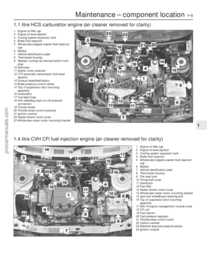 6
6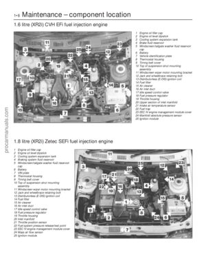 7
7 8
8 9
9 10
10 11
11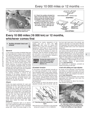 12
12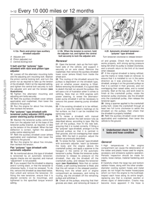 13
13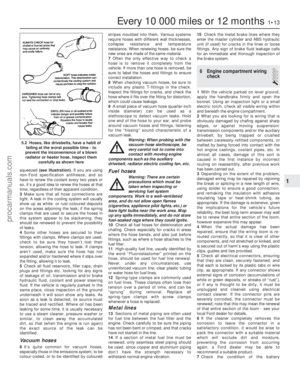 14
14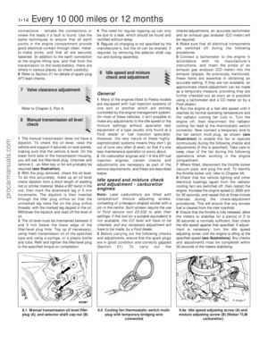 15
15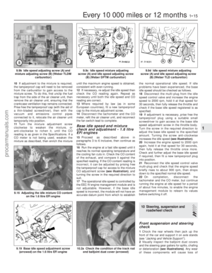 16
16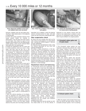 17
17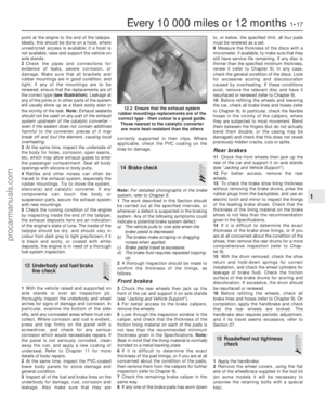 18
18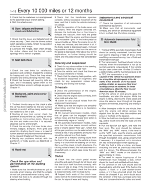 19
19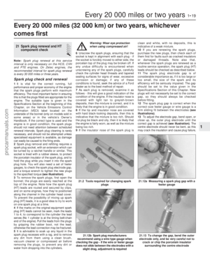 20
20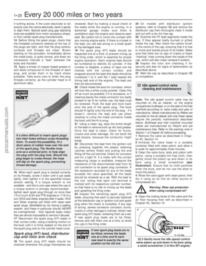 21
21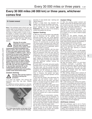 22
22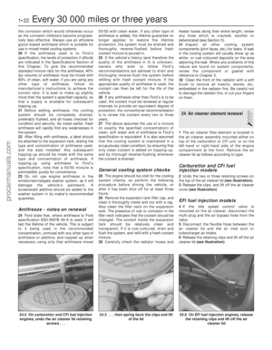 23
23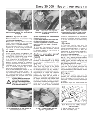 24
24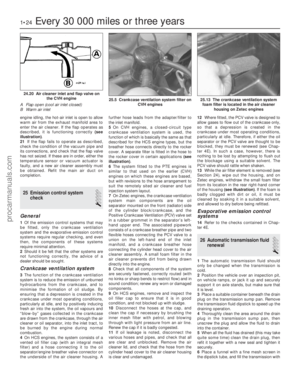 25
25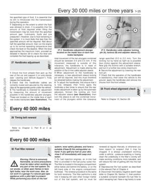 26
26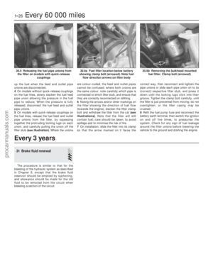 27
27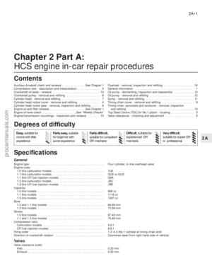 28
28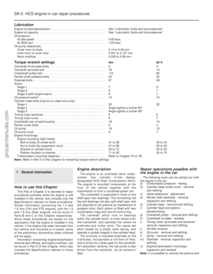 29
29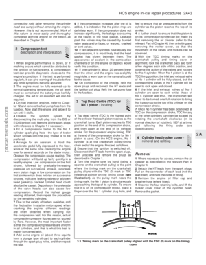 30
30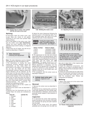 31
31 32
32 33
33 34
34 35
35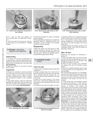 36
36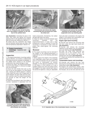 37
37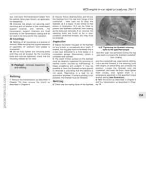 38
38 39
39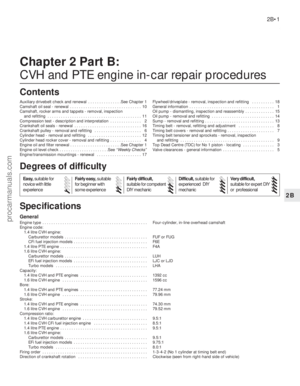 40
40 41
41 42
42 43
43 44
44 45
45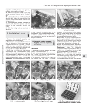 46
46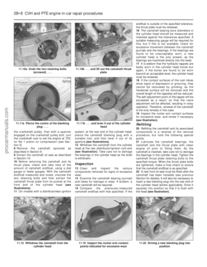 47
47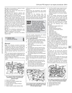 48
48 49
49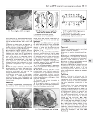 50
50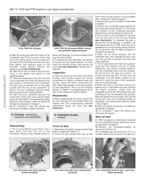 51
51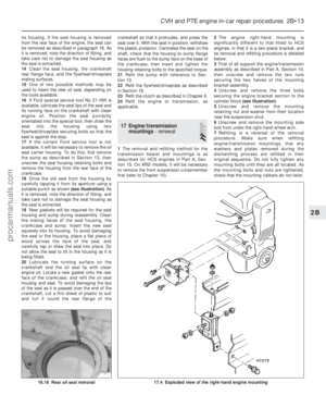 52
52 53
53 54
54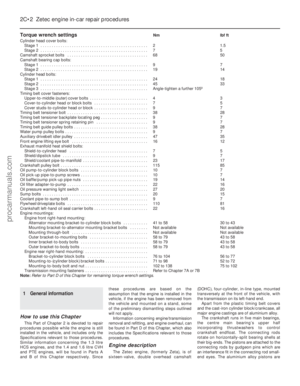 55
55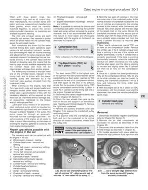 56
56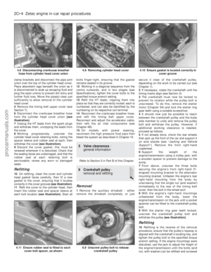 57
57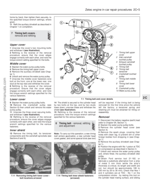 58
58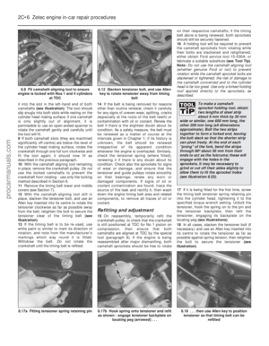 59
59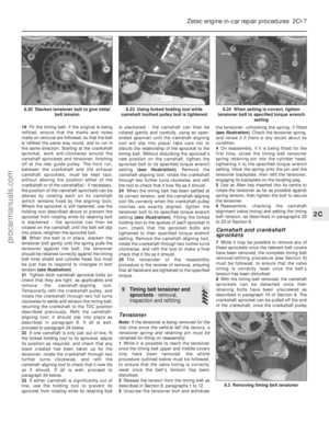 60
60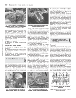 61
61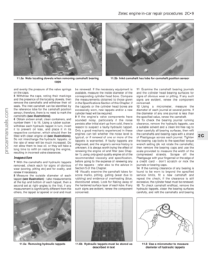 62
62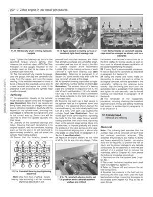 63
63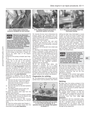 64
64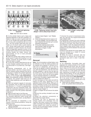 65
65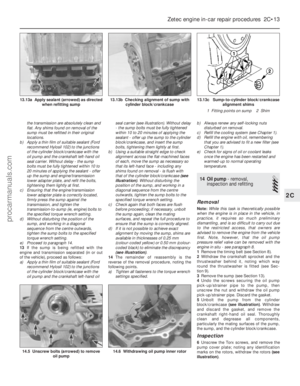 66
66 67
67 68
68 69
69 70
70 71
71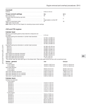 72
72 73
73 74
74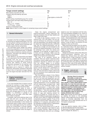 75
75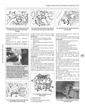 76
76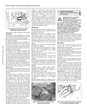 77
77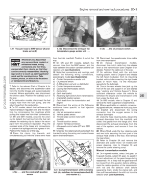 78
78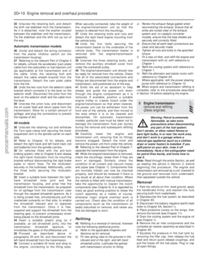 79
79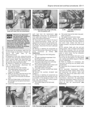 80
80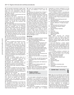 81
81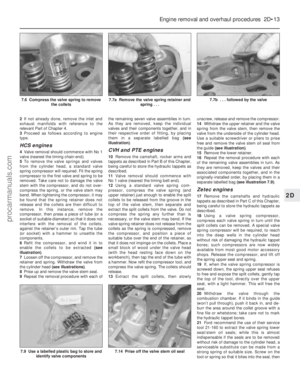 82
82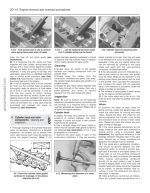 83
83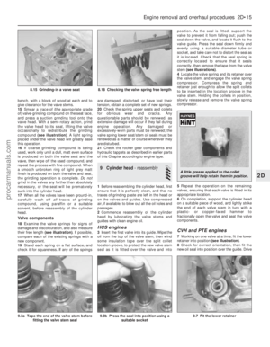 84
84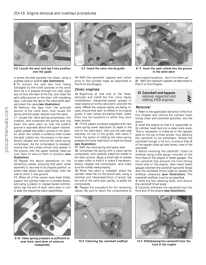 85
85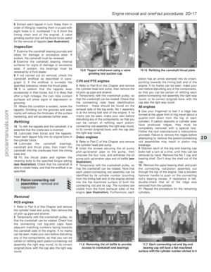 86
86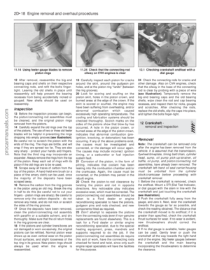 87
87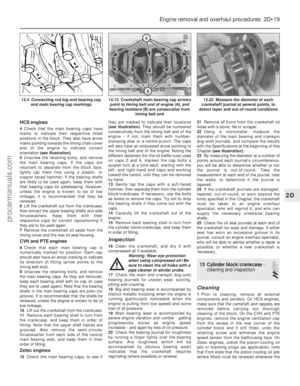 88
88 89
89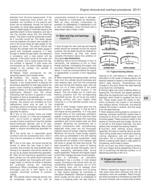 90
90 91
91 92
92 93
93 94
94 95
95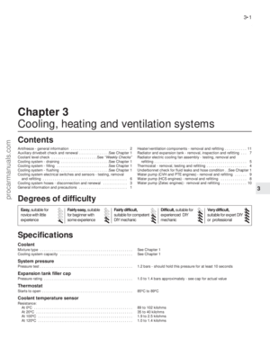 96
96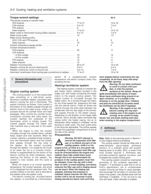 97
97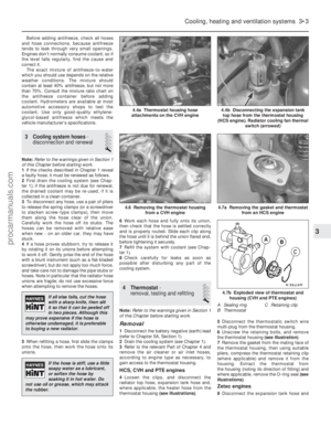 98
98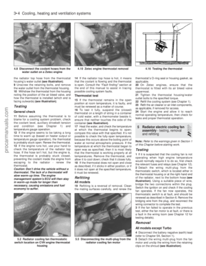 99
99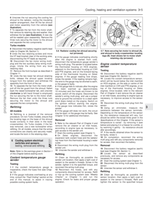 100
100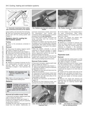 101
101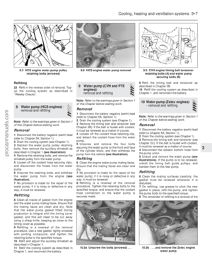 102
102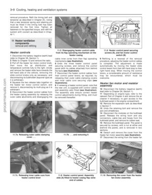 103
103 104
104 105
105 106
106 107
107 108
108 109
109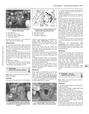 110
110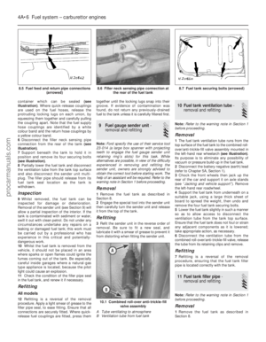 111
111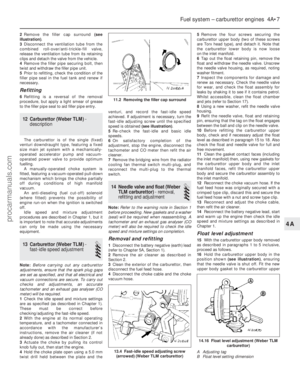 112
112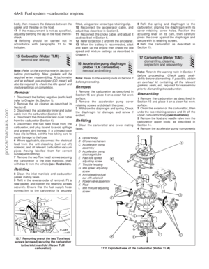 113
113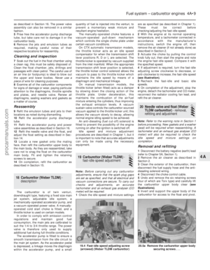 114
114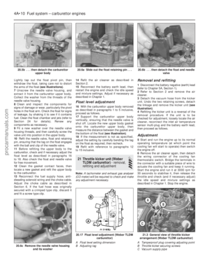 115
115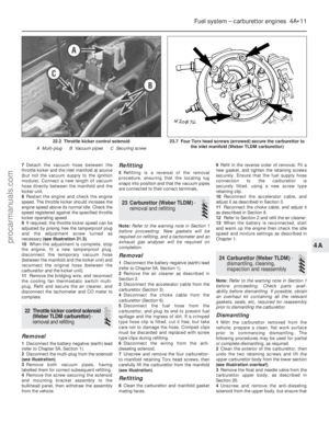 116
116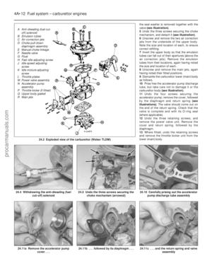 117
117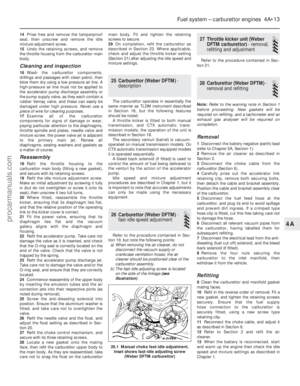 118
118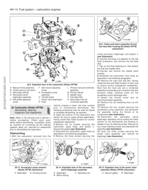 119
119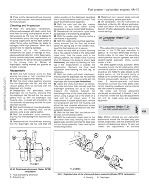 120
120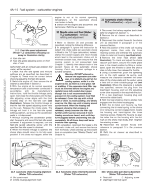 121
121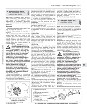 122
122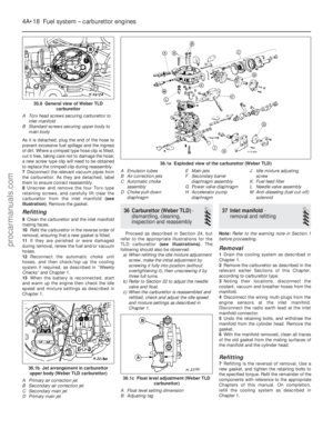 123
123 124
124 125
125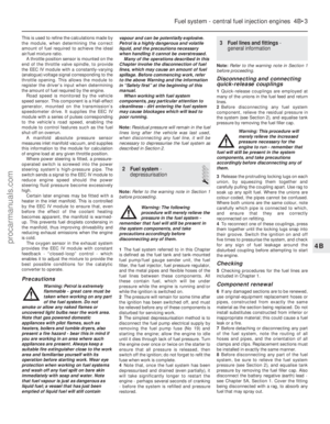 126
126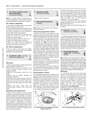 127
127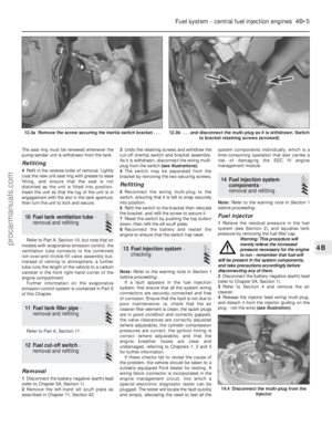 128
128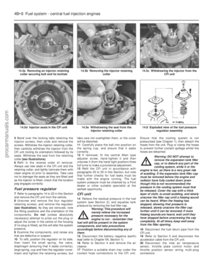 129
129 130
130 131
131 132
132 133
133 134
134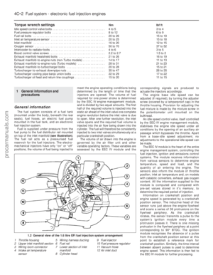 135
135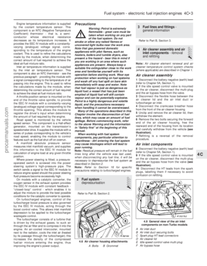 136
136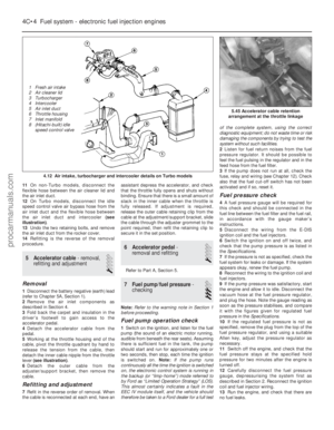 137
137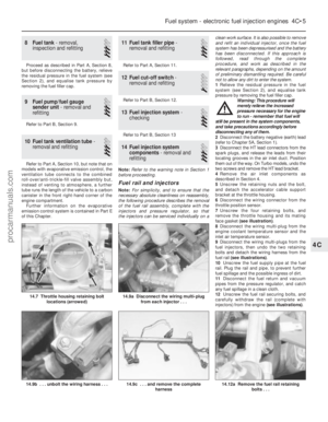 138
138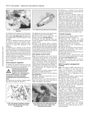 139
139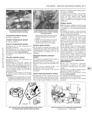 140
140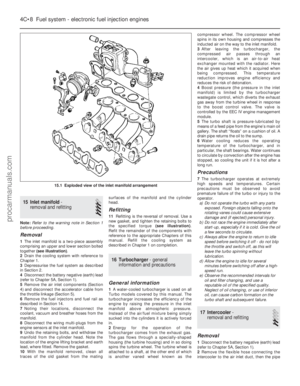 141
141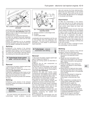 142
142 143
143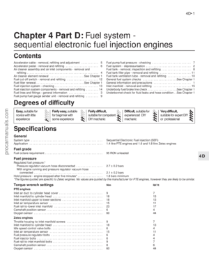 144
144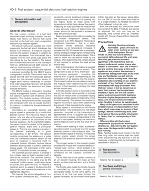 145
145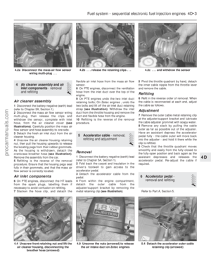 146
146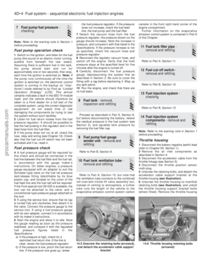 147
147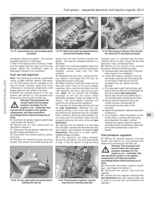 148
148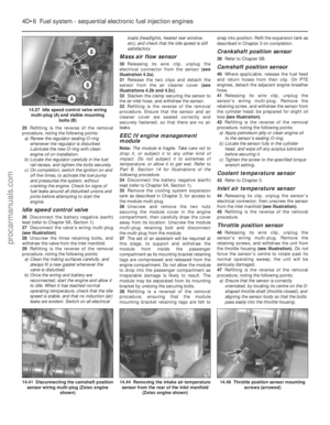 149
149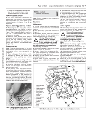 150
150 151
151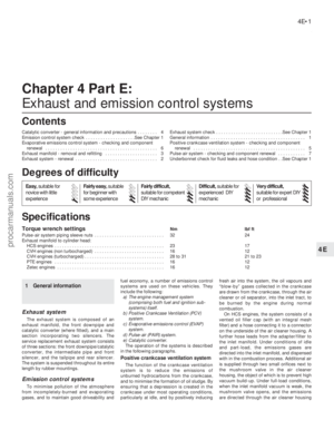 152
152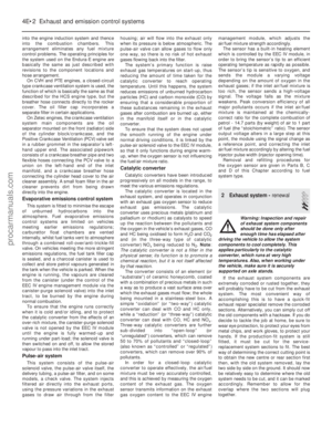 153
153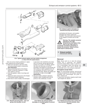 154
154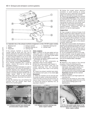 155
155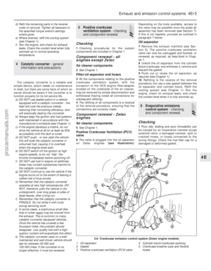 156
156 157
157 158
158 159
159 160
160 161
161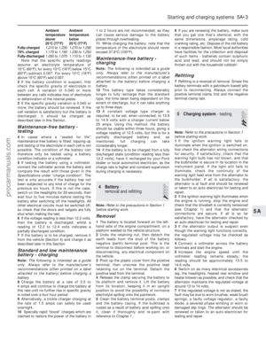 162
162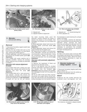 163
163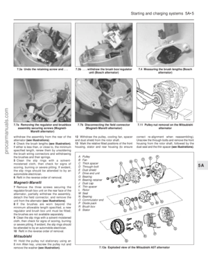 164
164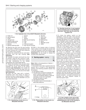 165
165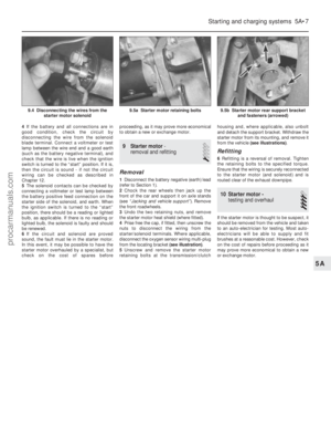 166
166 167
167 168
168 169
169 170
170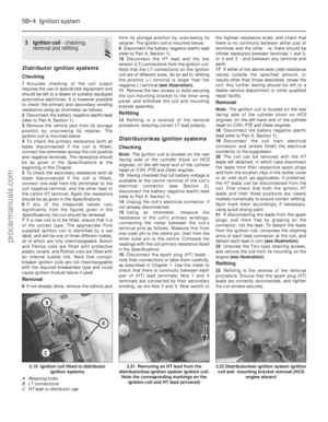 171
171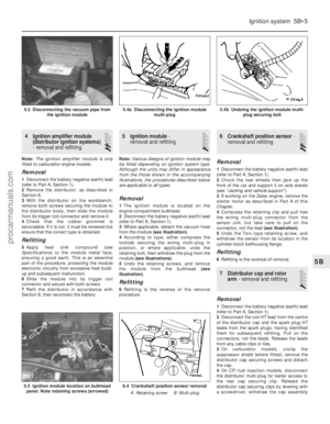 172
172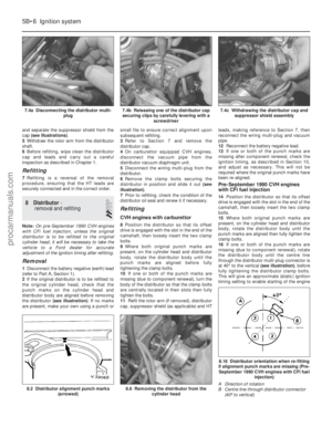 173
173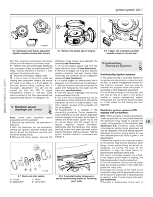 174
174 175
175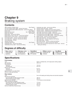 176
176 177
177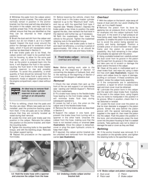 178
178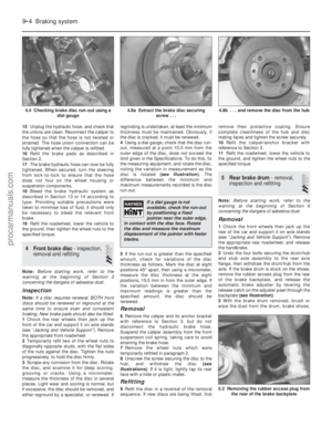 179
179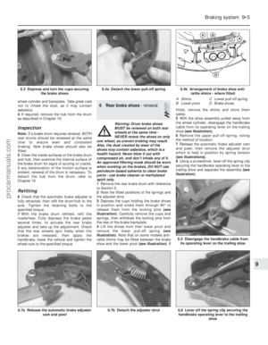 180
180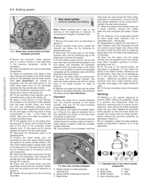 181
181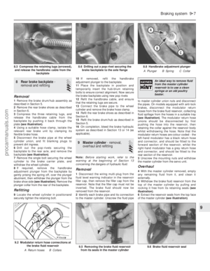 182
182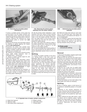 183
183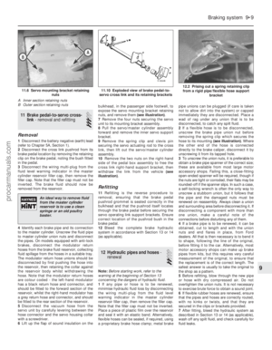 184
184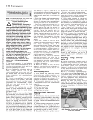 185
185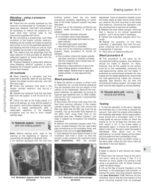 186
186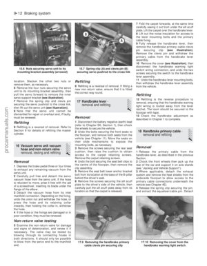 187
187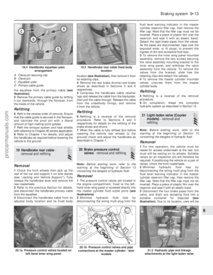 188
188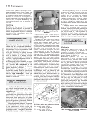 189
189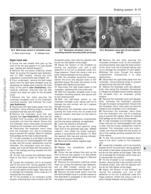 190
190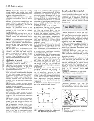 191
191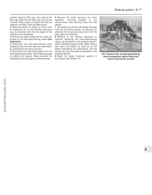 192
192 193
193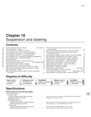 194
194 195
195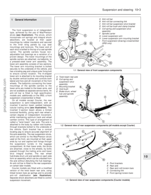 196
196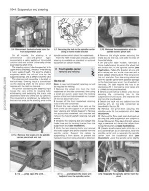 197
197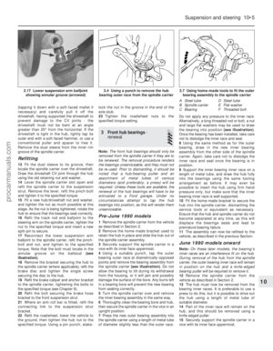 198
198 199
199 200
200 201
201 202
202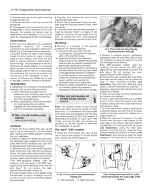 203
203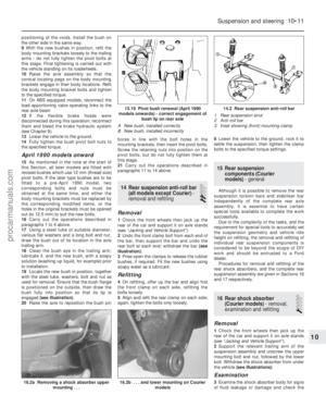 204
204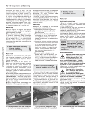 205
205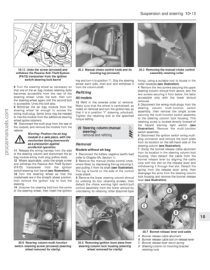 206
206 207
207 208
208 209
209 210
210 211
211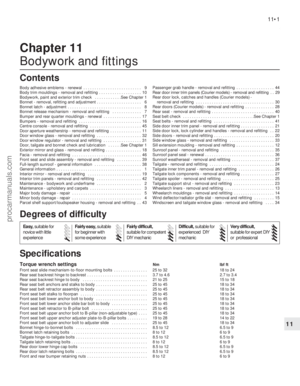 212
212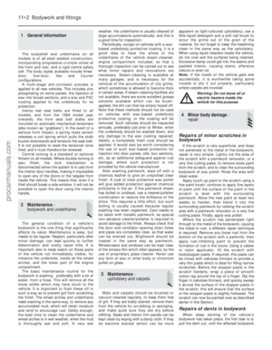 213
213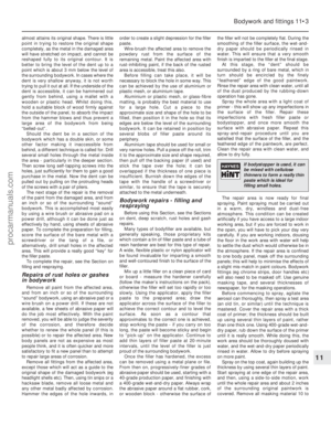 214
214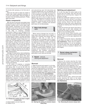 215
215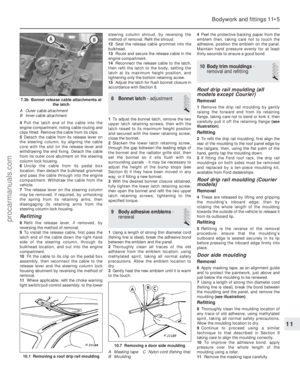 216
216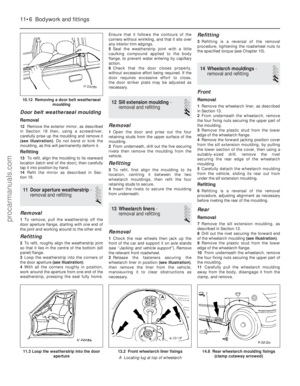 217
217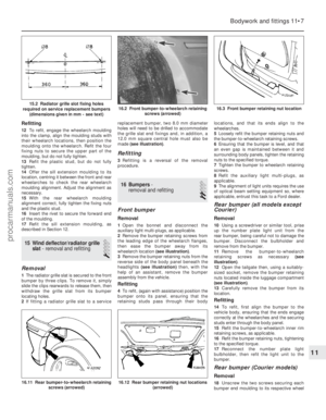 218
218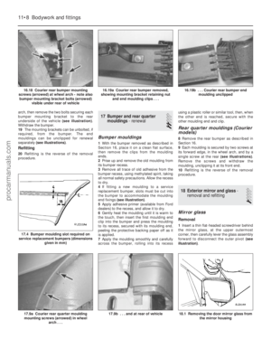 219
219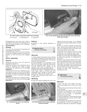 220
220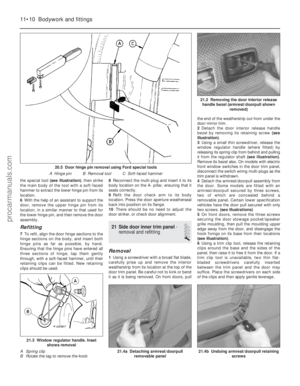 221
221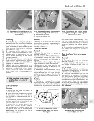 222
222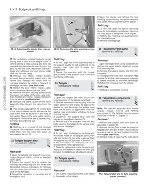 223
223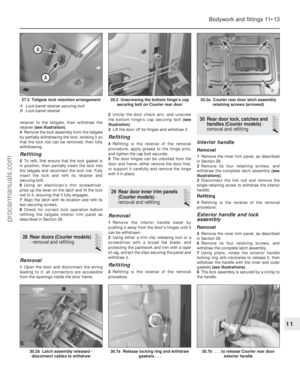 224
224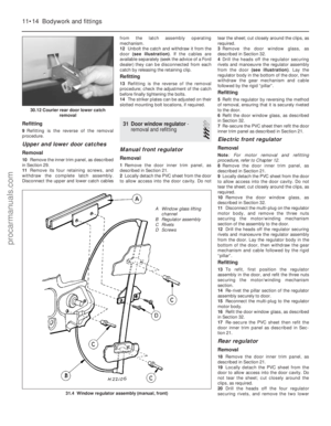 225
225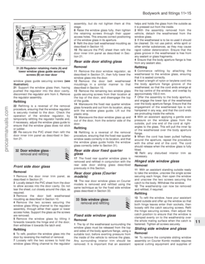 226
226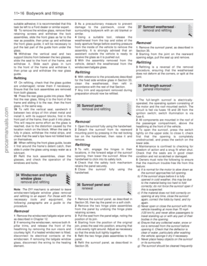 227
227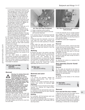 228
228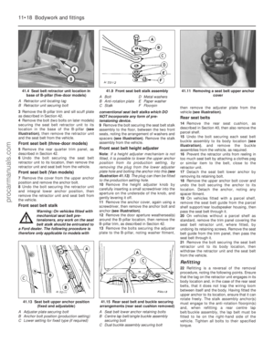 229
229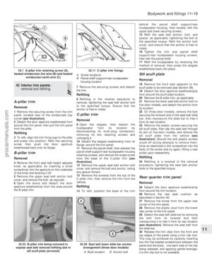 230
230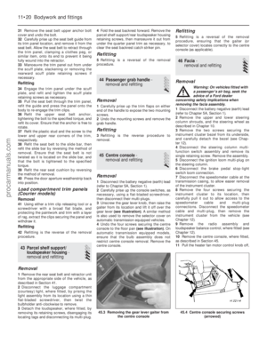 231
231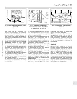 232
232 233
233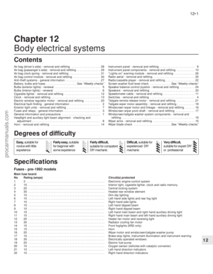 234
234 235
235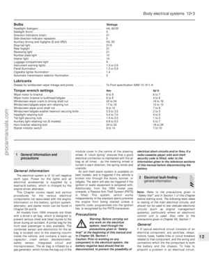 236
236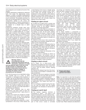 237
237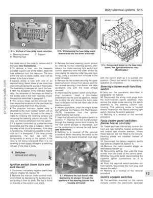 238
238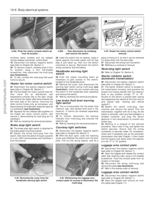 239
239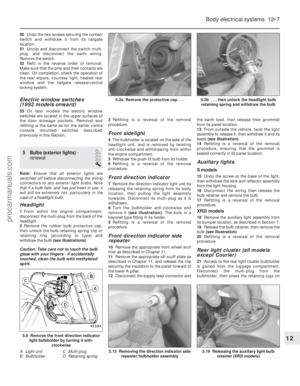 240
240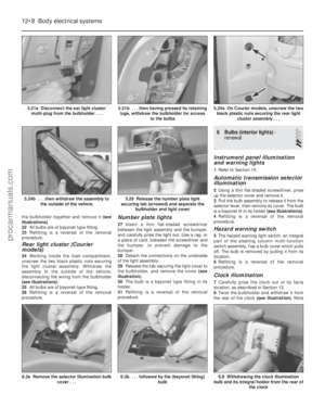 241
241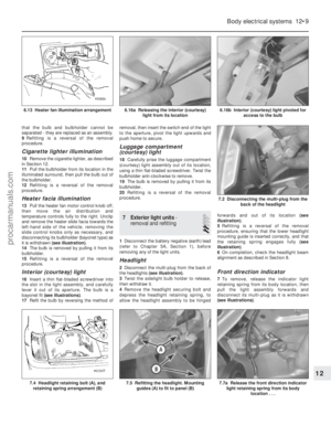 242
242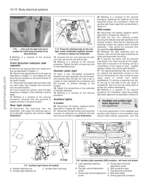 243
243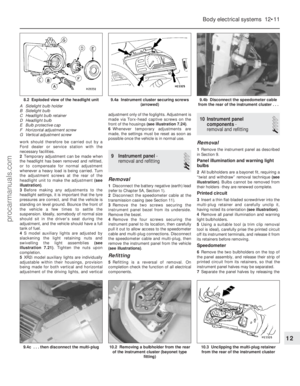 244
244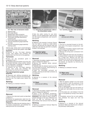 245
245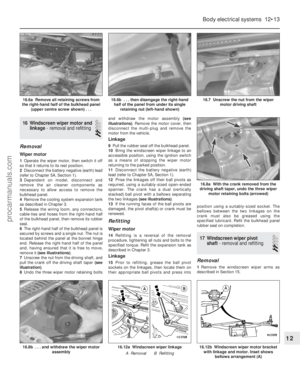 246
246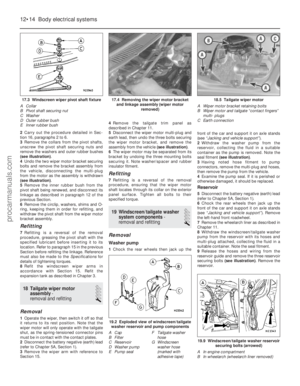 247
247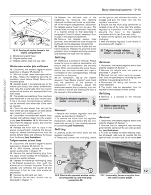 248
248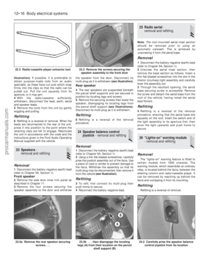 249
249 250
250 251
251 252
252 253
253 254
254 255
255 256
256 257
257 258
258 259
259 260
260 261
261 262
262 263
263 264
264 265
265 266
266 267
267 268
268 269
269 270
270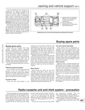 271
271 272
272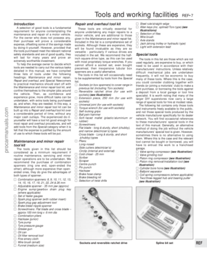 273
273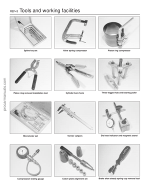 274
274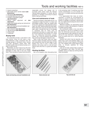 275
275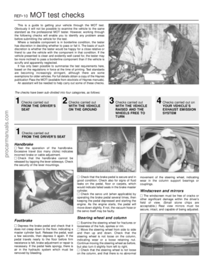 276
276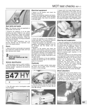 277
277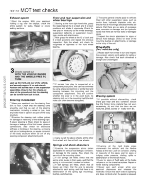 278
278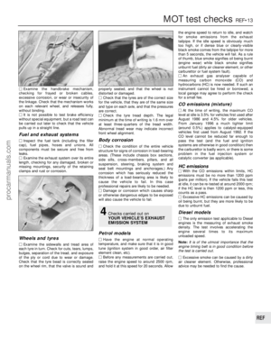 279
279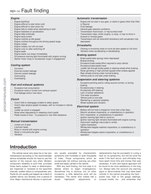 280
280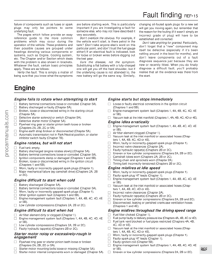 281
281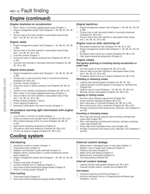 282
282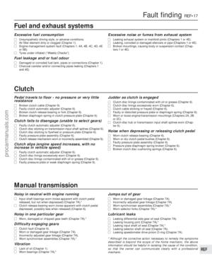 283
283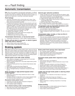 284
284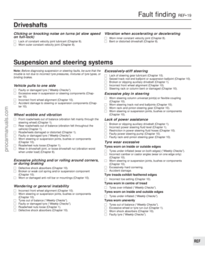 285
285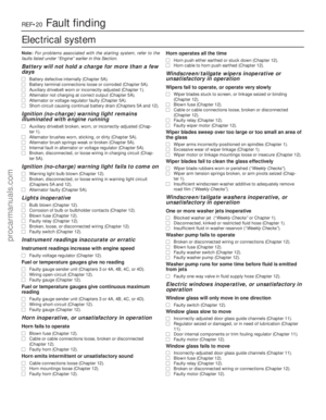 286
286 287
287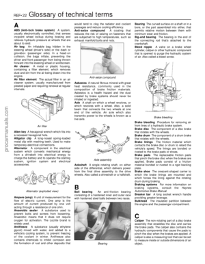 288
288 289
289 290
290 291
291 292
292 293
293 294
294 295
295