Page 129 of 296

5Bend over the locking tabs retaining the
injector screws, then undo and remove the
screws. Withdraw the injector retaining collar,
then carefully withdraw the injector from the
CFi unit (noting its orientation) followed by its
seals. Withdraw the seal from the retaining
collar (see illustrations) .
6 Refit in the reverse order of removal.
Always use new seals in the CFi unit and the
retaining collar, and lightly lubricate them with
clean engine oil prior to assembly. Take care
not to damage the seals as they are fitted and
as the injector is fitted, check that the location
peg engages correctly.
Fuel pressure regulator
7 Refer to paragraphs 14 to 22 in this Section
and remove the CFi unit from the vehicle.
8 Unscrew and remove the four regulator
retaining screws, and remove the regulator
(see illustration) . As they are removed, note
the fitting positions and the orientation of the
components. Do not(unless absolutely
necessary) attempt to prise out the plug or
adjust the screw in the centre of the housing
(if no plug is fitted), as this will alter the system
pressure.
9 Examine the components, and renew any
that are defective or suspect.
10 To refit, position the regulator on its side,
then insert the small spring, the valve,
diaphragm (ensuring that it seats correctly),
large spring, cup and then the regulator cover.
Insert and tighten the retaining screws, but take care not overtighten them, or the cover
will be distorted.
11
Carefully place the ball into position on
the spring cup, and ensure that it seats
correctly.
12 If removed, fit the central Allen type
adjuster screw, hand-tighten it and then
unscrew it (from the hand-tight position) three
full turns to make a provisional adjustment.
13 Refit the CFi unit in accordance with
paragraphs 23 to 25 in this Section, but note
that further checks for fuel leaks must be
made with the engine running. The fuel
system pressure must be checked by a Ford
dealer or other suitable specialist at the
earliest opportunity.CFi unit
14 Relieve the residual pressure in the fuel
system (see Section 2), and equalise tank
pressure by removing the fuel filler cap. Warning: This procedure will
merely relieve the increased
pressure necessary for the
engine to run - remember that
fuel will still be present in the system
components, and take precautions
accordingly before disconnecting any of
them.
15 Disconnect the battery negative (earth)
lead (refer to Chapter 5A, Section 1).
16 Refer to Section 4 and remove the air
cleaner.
17 Position a suitable drain tray under the
coolant hose connections to the CFi unit. Ensure that the cooling system is not
pressurised (see Chapter 1), then detach the
hoses from the unit. Plug or clamp the hoses
to prevent further coolant spillage whilst the
hoses are detached.
Warning: DO NOT attempt to
remove the expansion tank filler
cap, or to disturb any part of the
cooling system, while it or the
engine is hot, as there is a very great risk
of scalding. If the expansion tank filler cap
must be removed before the engine and
radiator have fully cooled down (even
though this is not recommended) the
pressure in the cooling system must first
be released. Cover the cap with a thick
layer of cloth, to avoid scalding, and slowly
unscrew the filler cap until a hissing sound
can be heard. When the hissing has
stopped, showing that pressure is
released, slowly unscrew the filler cap
further until it can be removed; if more
hissing sounds are heard, wait until they
have stopped before unscrewing the cap
completely. At all times, keep well away
from the filler opening.
18 Disconnect the fuel return pipe from the
CFi unit.
19 Refer to Section 5 and disconnect the
accelerator cable from the CFi unit.
20 Disconnect the inlet air temperature
sensor, throttle plate control motor and
throttle position sensor wiring multi-plug
connectors.
4B•6 Fuel system - central fuel injection engines
14.8 Exploded view of the fuel pressure
regulator assembly14.5e Withdrawing the seal from theinjector retaining collar14.5d Injector seals in the CFi unit
14.5c Withdrawing the injector from the CFi unit14.5b Removing the injector retainingcollar14.5a Removing an injector retainingcollar securing bolt and its locktab
1595Ford Fiesta Remakeprocarmanuals.com
http://vnx.su
Page 130 of 296
 . Remove the
gasket.
23 Clean the C")
21Disconnect the vacuum hose from the CFi
unit.
22 Unscrew and remove the four retaining
screws, and remove the CFi unit from the inlet
manifold (see illustration) . Remove the
gasket.
23 Clean the CFi unit and the inlet manifold
mating faces.
24 Refit in the reverse order of removal.
Tighten the retaining bolts to the specified
torque wrench setting. Check and top-up the
cooling system as required (see “Weekly
Checks” and Chapter 1).
25 When the CFi unit is refitted, turn the
ignition on and off at least five times to
pressurise the system, and check for leaks.
Throttle plate control motor
26 Disconnect the battery negative (earth)
lead (refer to Chapter 5A, Section 1).
27 Refer to Section 4 and remove the air
cleaner.
28 Detach the wiring multi-plugs from the
throttle position sensor and the throttle plate
control motor, and release the retaining clips
on the bracket (see illustrations) .
29 Undo and remove the motor support
bracket screws, and remove the bracket
complete with the motor from the CFi unit
(see illustration) .
30 Undo the motor retaining screws and
remove it from the support bracket.
31 Refit in the reverse order of removal, but
note the following points: a) When refitting the motor and its support
bracket to the injector unit, the throttle
position sensor must locate on the
accelerator linkage, and the bracket must
align with the pegs.
b) On completion, the idle speed should be
checked by a Ford dealer or fuel injection
specialist who has the required
equipment to link up with the EEC IV
engine management module.
Fuel trap
32 A fuel trap is fitted to the manifold
absolute pressure sensor vacuum hose on
certain models.
33 To remove the fuel trap, disconnect the
vacuum hoses from the fuel trap and withdraw it.
34 Refit in the reverse order of removal. It is
important to ensure that the trap is correctly
orientated, with the “CARB” mark on one end face towards the inlet manifold, and the
“DIST” mark towards the MAP sensor
(see
illustration) .
EEC IV engine management
module
Note: The module is fragile. Take care not to
drop it, or subject it to any other kind of
impact. Do not subject it to extremes of
temperature, or allow it to get wet.
35 Disconnect the battery negative (earth)
lead (refer to Chapter 5A, Section 1).
36 Unscrew and remove the two nuts
securing the module cover in the engine
compartment, then carefully draw the cover
away from its location. Unscrew the module
multi-plug retaining bolt and disconnect the
multi-plug from the module (see illustrations).
37 The aid of an assistant will be required at
this stage, to support and withdraw the
Fuel system - central fuel injection engines 4B•7
14.28b Disconnecting the throttle plate control motor multi-plug14.28a Release the throttle position
sensor multi-plug from its retaining clip and disconnect it14.22 CFi unit securing screws (arrowed)
14.36b Undoing the EEC IV engine
management module multi-plug retaining
bolt
14.34 Fuel trap vacuum connection markings14.29 Throttle-plate control motor andthrottle position sensor assembly
mounting bracket securing screws (arrowed)
14.36a Undoing the EEC IV engine
management module cover retaining nuts
(vehicle jack removed for clarity)
4B
1595Ford Fiesta Remakeprocarmanuals.com
http://vnx.su
Page 131 of 296

module from inside the passenger
compartment as its mounting bracket
retaining tags are compressed and released
from the engine compartment. Do not allow
the module to drop into the passenger
compartment as irreparable damage is likely
to result (see illustration) . The module may
be separated from its mounting bracket by
undoing the securing bolts.
38 Refitting is a reversal of the removal
procedure, ensuring that the module
mounting bracket retaining tags are felt to
snap into position
Crankshaft position sensor
39 Refer to Chapter 5B.
Coolant temperature sensor
40Refer to Chapter 3.
Inlet air temperature sensor
41Remove the air cleaner assembly as
described in Section 4.
42 Releasing its clip, unplug the sensor’s
electrical connector, then unscrew the sensor
from the CFi unit (see illustration).
43 Refitting is the reverse of the removal
procedure. Tighten the sensor to the specified
torque wrench setting; if it is overtightened, its
tapered thread may crack the resonator.
Throttle position sensor
44 Remove the air cleaner assembly as
described in Section 4.
45 Releasing its wire clip, unplug the
sensor’s wiring connector. Remove the
retaining screws, and withdraw the unit from
the throttle plate control motor bracket (see
illustration) . Do not force the sensor’s centre
to rotate past its normal operating sweep; the
unit will be seriously damaged.
46 Refitting is the reverse of the removal
procedure, ensuring that the sensor actuating
arm is correctly located.
Vehicle speed sensor
47 The sensor is mounted at the base of the
speedometer drive cable, and is removed with
the speedometer drive pinion. Refer to the
relevant Section of Chapter 7A or B, as
applicable.
Manifold absolute pressure
sensor
48 The sensor is located near the centre of
the engine compartment bulkhead.
49 Disconnect the wiring multi-plug, and
detach the vacuum hose from the base of the
sensor (see illustration) .
50 Undo the two retaining screws, and
withdraw the sensor from its location. 51
Refitting is the reverse of the removal
procedure.
Power steering pressure switch
52 Releasing its clip, unplug the switch’s
electrical connector, then unscrew the switch
from the power steering high pressure pipe.
Place a wad of rag underneath, to catch any
spilt fluid. If a sealing washer is fitted, renew it
if it is worn or damaged.
53 Refitting is the reverse of the removal
procedure; tighten the switch securely, then
top-up the fluid reservoir (see “Weekly
Checks” ) to replace any fluid lost from the
system, and bleed out any trapped air (see
Chapter 10).
Oxygen sensor
Note: The sensor is delicate, and will not work
if it is dropped or knocked, if its power supply
is disrupted, or if any cleaning materials are
used on it.
54 Release the sensor’s electrical connector
from its bracket and unplug it to disconnect
the sensor (see illustration) .
55 Raise and support the front of the vehicle
if required to remove the sensor from
underneath (“see Jacking and vehicle
support” ). Remove the sensor heat shield then
unscrew the sensor from the exhaust system
front downpipe; collect the sealing washer
(where fitted).
56 On refitting, clean the sealing washer
(where fitted) and renew it if it is damaged or
4B•8 Fuel system - central fuel injection engines
14.54 Oxygen sensor (A) (shown with its
heatshield removed), and its multi-plug (B)
14.49 Manifold absolute pressure sensor location
A Securing screws B Multi-plug C Vacuum hose\
Arrows indicate ignition module retaining screws
14.45 Throttle position sensor retainingscrews (arrowed) (shown with throttle plate control motor removed)14.42 Disconnecting the intake airtemperature sensor multi-plug
1595Ford Fiesta Remake
14.37 Withdrawing the EEC IV engine
management module into the passenger footwellprocarmanuals.com
http://vnx.su
Page 132 of 296

worn. Apply a smear of anti-seize compound
to the sensor’s threads, to prevent them from
welding themselves to the downpipe in
service. Refit the sensor, tightening it to its
specified torque wrench setting; a slotted
socket will be required to do this. Reconnect
the wiring, and heat shield then refit the
connector plug.
Inlet manifold heater
57The heater is located in a recess in the
inlet manifold, directly underneath the CFi
unit. While access is possible from
underneath, it is preferable, depending on the
tools available, to remove the complete
manifold (Section 15) to reach the heater.
58 Assuming the work is being carried out
without removing the manifold, disconnect
the battery negative (earth) lead (refer to
Chapter 5A, Section 1).
59 Chock the rear wheels then jack up the
front of the car and support it on axle stands
(see “Jacking and vehicle support” ).
60 Disconnect the heater wiring, and extract
the circlip retaining the heater (see
illustration) . Withdraw the heater.
61 Refitting is the reverse of the removal
procedure. Ensure that both the heater and its
circlip are correctly located in the manifold.
Injector ballast resistor
62 When fitted, this component is located on
the engine compartment bulkhead, next to the
manifold absolute pressure sensor.
63 Disconnect the battery negative (earth)
lead (refer to Chapter 5A, Section 1).
64 Disconnect the resistor wiring at its multi-
plug, remove the retaining screw and
withdraw the resistor.
65 Refitting is the reverse of the removal
procedure.
15 Inlet manifold -
removal and refitting
3
Note: Refer to the warning note in Section 1
before proceeding.
Removal
1 Drain the cooling system as described in
Chapter 1.
2 Remove the CFi unit as described in
Section 14.
3 Noting their locations, disconnect the
coolant, vacuum and breather hoses from the
manifold.
4 Disconnect the wiring multi-plugs from the engine sensors at the inlet manifold.
Disconnect the radio earth lead at the inlet
manifold connector.
5
Undo the retaining bolts, and withdraw the
manifold from the cylinder head. Remove the
gasket.
6 With the manifold removed, clean all traces
of the old gasket from the mating surfaces of
the manifold and the cylinder head.
Refitting
7 Refitting is the reversal of removal. Use a
new gasket, and tighten the retaining bolts to
the specified torque. Refit the remainder of
the components with reference to the
appropriate Chapters of this manual.
Fuel system - central fuel injection engines 4B•9
14.60 Inlet manifold heater components
4B
1595Ford Fiesta Remakeprocarmanuals.com
http://vnx.su
Page 133 of 296
4B•10 Fuel system - central fuel injection engines
1595Ford Fiesta Remake
Notes
procarmanuals.com
http://vnx.su
Page 134 of 296
 with turbocharger on RS Tur")
4C
1595Ford Fiesta Remake
General
System type . . . . . . . . . . . . . . . . . . . . . . . . . . . . . . . . . . . .\
. . . . . . . . . . Electronic Fuel injection (EFi) with turbocharger on RS Turbo models
Application . . . . . . . . . . . . . . . . . . . . . . . . . . . . . . . . . . . .\
. . . . . . . . . . . 1.6 litre CVH engines
Fuel grade
Fuel octane requirement:Engines without catalytic converter* . . . . . . . . . . . . . . . . . . . . . . . . . . 95 RON unleaded or 97 RON leaded
Engines with catalytic converter . . . . . . . . . . . . . . . . . . . . . . . . . . . . . 95 RON unleaded (leaded fuel must notbe used)
*Refer to dealer for latest recommendations
Fuel system data
Idle speed and mixture settings . . . . . . . . . . . . . . . . . . . . . . . . . . . . . . . See Chapter 1
Fuel pump pressure - engine not running . . . . . . . . . . . . . . . . . . . . . . . 3.0 bars minimum
Regulated fuel pressure - engine running at idle speed . . . . . . . . . . . . . 2.3 to 2.5 bars
Hold pressure - engine stopped after two minutes . . . . . . . . . . . . . . . . Not less than 0.8 bars below regulated pressure
Turbocharger
Type . . . . . . . . . . . . . . . . . . . . . . . . . . . . . . . . . . . .\
. . . . . . . . . . . . . . . . Garrett AiResearch T02
Boost pressure . . . . . . . . . . . . . . . . . . . . . . . . . . . . . . . . . . . .\
. . . . . . . . 0.47 to 0.51 bars
Chapter 4 Part C:
Fuel system - electronic fuel injection engines
Accelerator cable - removal, refitting and adjustment . . . . . . . . . . . 5
Accelerator pedal - removal and refitting . . . . . . . . . . . . . . . . . . . . . 6
Air cleaner assembly and air inlet components - removal and
refitting . . . . . . . . . . . . . . . . . . . . . . . . . . . . . . . . . . . .\
. . . . . . . . . . 4
Air cleaner element renewal . . . . . . . . . . . . . . . . . . . . . .See Chapter 1
Exhaust system check . . . . . . . . . . . . . . . . . . . . . . . . . . .See Chapter 1
Fuel cut-off switch - removal and refitting . . . . . . . . . . . . . . . . . . . . 12
Fuel filter renewal . . . . . . . . . . . . . . . . . . . . . . . . . . \
. . . . .See Chapter 1
Fuel injection system - checking . . . . . . . . . . . . . . . . . . . . . . . . . . . . 13
Fuel injection system components - removal and refitting . . . . . . . . 14
Fuel lines and fittings - general information . . . . . . . . . . . . . . . . . . . 3
Fuel pump/fuel gauge sender unit - removal and refitting . . . . . . . . 9
Fuel pump/fuel pressure - checking . . . . . . . . . . . . . . . . . . . . . . . . . 7
Fuel system - depressurisation . . . . . . . . . . . . . . . . . . . . . . . . . . . . . 2
Fuel tank - removal, inspection and refitting . . . . . . . . . . . . . . . . . . . 8 Fuel tank filler pipe - removal and refitting . . . . . . . . . . . . . . . . . . . . 11
Fuel tank ventilation tube - removal and refitting . . . . . . . . . . . . . . . 10
General fuel system checks . . . . . . . . . . . . . . . . . . . . . .See Chapter 1
General information and precautions . . . . . . . . . . . . . . . . . . . . . . . . 1
Idle speed and mixture check and adjustment . . . . . . . .See Chapter 1
Idle speed control valve cleaning and maintenance . . . .See Chapter 1
Inlet manifold - removal and refitting . . . . . . . . . . . . . . . . . . . . . . . . 15
Intercooler - removal and refitting . . . . . . . . . . . . . . . . . . . . . . . . . . . 17
Turbocharger - general information and precautions . . . . . . . . . . . . 16
Turbocharger - removal, examination and refitting . . . . . . . . . . . . . . 20
Turbocharger boost control valve - removal and refitting . . . . . . . . . 18
Turbocharger boost pressure - checking and adjustment . . . . . . . . 19
Underbody fuel/brake line check . . . . . . . . . . . . . . . . . . .See\
Chapter 1
Underbonnet check for fluid leaks and hose condition . .See Chapter 1
4C•1
Specifications Contents
Easy,
suitable for
novice with little
experience Fairly easy,
suitable
for beginner with
some experience Fairly difficult,
suitable for competent
DIY mechanic
Difficult,
suitable for
experienced DIY
mechanic Very difficult,
suitable for expert DIY
or professional
Degrees of difficulty
54321
procarmanuals.com
http://vnx.su
Page 135 of 296

Torque wrench settingsNmlbf ft
Idle speed control valve bolts . . . . . . . . . . . . . . . . . . . . . . . . . . . . . . . . . 4 to 5 3 to 4
Fuel pressure regulator bolts . . . . . . . . . . . . . . . . . . . . . . . . . . . . . . . . . 8 to 12 6 to 9
Fuel rail bolts . . . . . . . . . . . . . . . . . . . . . . . . . . . . . . . . . . . .\
. . . . . . . . . 20 to 26 15 to 19
Inlet air temperature sensor . . . . . . . . . . . . . . . . . . . . . . . . . . . . . . . . . . 20 to 25 15 to 18
Inlet manifold . . . . . . . . . . . . . . . . . . . . . . . . . . . . . . . . . . . .\
. . . . . . . . . 16 to 20 12 to 15
Oxygen sensor . . . . . . . . . . . . . . . . . . . . . . . . . . . . . . . . . . . .\
. . . . . . . . 50 to 70 37 to 52
Intercooler-to-radiator bolts . . . . . . . . . . . . . . . . . . . . . . . . . . . . . . . . . . 4 to 6 3 to 5
Boost control valve screws . . . . . . . . . . . . . . . . . . . . . . . . . . . . . . . . . . . 2.2 to 2.7 1.5 to 2
Exhaust manifold heatshield bolts . . . . . . . . . . . . . . . . . . . . . . . . . . . . . 21 to 26 16 to 19
Exhaust manifold-to-engine nuts (non-Turbo models) . . . . . . . . . . . . . . 14 to 17 11 to 13
Exhaust manifold-to-engine nuts (Turbo models) . . . . . . . . . . . . . . . . . 28 to 31 21 to 23
Exhaust manifold-to-turbocharger bolts . . . . . . . . . . . . . . . . . . . . . . . . 20 to 28 15 to 21
Turbocharger-to-exhaust downpipe nuts . . . . . . . . . . . . . . . . . . . . . . . . 35 to 47 26 to 35
Turbocharger cooling pipe banjo union bolts . . . . . . . . . . . . . . . . . . . . . 22 to 29 17 to 22
Turbocharger oil feed and return line couplings . . . . . . . . . . . . . . . . . . . 15 to 20 11 to 15
4C•2 Fuel system - electronic fuel injection engines
1595Ford Fiesta Remake
1 General information and
precautions
General information
The fuel system consists of a fuel tank
(mounted under the body, beneath the rear
seats), fuel hoses, an electric fuel pump
mounted in the fuel tank, and an electronic
fuel injection system. Fuel is supplied under pressure from the
fuel pump to the fuel distributor rail mounted
on top of the inlet manifold (see illustration).
The fuel rail acts as a pressurised fuel
reservoir for the fuel injectors. The electro-
mechanical injectors have only “on” or “off”
positions, the volume of fuel being injected to meet the engine operating conditions being
determined by the length of time that the
injectors are opened. The volume of fuel
required for one power stroke is determined
by the EEC IV engine management module,
and is divided by two equal amounts. The first
half of the required volume is injected into the
static air ahead of the inlet valve one complete
engine revolution before the inlet valve is due
to open. After one further revolution, the inlet
valve opens and the required fuel volume is
injected into the air flow being drawn into the
cylinder. The fuel will therefore be consistently
injected to two inlet valves simultaneously at a
particular crankshaft position.
The volume of air drawn into the engine is
governed by the air filter unit and other
variable operating factors. These variables are
assessed by the EEC IV module and the corresponding signals are produced to
actuate the injectors accordingly.
The engine base idle speed can be
adjusted (if required), by turning the adjuster
screw (covered by a tamperproof cap) in the
throttle housing. Provision for adjusting the
fuel mixture is made by the mixture screw in
the potentiometer unit mounted on the
bulkhead. An idle speed control valve, itself controlled
by the EEC-IV engine management module,
stabilises the engine idle speed under all
conditions by the opening of an auxiliary air
passage which bypasses the throttle. Apart
from a base-idle speed adjustment, no
adjustments to the operational idle speed can
be made. The EEC IV module is the heart of the entire
engine management system, controlling the
fuel injection, ignition and emissions control
systems. The module receives information
from various sensors to determine engine
temperature, speed and load, and the
quantity of air entering the engine. The
sensors also inform the module of throttle
position, inlet air temperature and, on models
with catalytic converters, exhaust gas oxygen
content. All the information supplied to the
module is computed and compared with
pre-set values stored in it’s memory, to
determine the required period of injection.
Information on crankshaft position and
engine speed is generated by a crankshaft
position sensor. The inductive head of the
sensor runs just above the engine flywheel
and scans a series of 36 protrusions on the
flywheel periphery. As the crankshaft
rotates, the sensor transmits a pulse to the
system’s ignition module every time a
protrusion passes it. There is one missing
protrusion in the flywheel periphery at a point
corresponding to 90° BTDC. The ignition
module recognises the absence of a pulse
from the crankshaft position sensor at this
point to establish a reference mark for
crankshaft position. Similarly, the time interval
between absent pulses is used to determine
engine speed. This information is then fed to
the EEC IV module for further processing.
1.2 General view of the 1.6 litre EFi fuel injection system arrangement\
1 Throttle housing
2 Upper inlet manifold section
3 Wiring loom connector
4 Intake air temperature sensor 5 Wiring harness ducting
6 Fuel rail
7 Lower section of inlet
manifold
8 Cylinder head 9 Fuel injector
10
Fuel pressure regulator
11 Vacuum hose
12 Air inlet duct
procarmanuals.com
http://vnx.su
Page 136 of 296
 thermistor - that is, a semi-
conductor whose electrical resis")
Engine temperature information is supplied
by the coolant temperature sensor. This
component is an NTC (Negative Temperature
Coefficient) thermistor - that is, a semi-
conductor whose electrical resistance
decreases as its temperature increases. It
provides the EEC IV module with a constantly-
varying (analogue) voltage signal, corre-
sponding to the temperature of the engine
coolant. This is used to refine the calculations
made by the module, when determining the
correct amount of fuel required to achieve the
ideal air/fuel mixture ratio. Inlet air temperature information is supplied
by the inlet air temperature sensor. This
component is also an NTC thermistor - see the
previous paragraph - providing the module with
a signal corresponding to the temperature of air
passing into the engine. This is used to refine
the calculations made by the module, when
determining the correct amount of fuel required
to achieve the ideal air/fuel mixture ratio. A throttle position sensor is mounted on the
end of the throttle valve spindle, to provide
the EEC IV module with a constantly-varying
(analogue) voltage signal corresponding to the
throttle opening. This allows the module to
register the driver’s input when determining
the amount of fuel required by the engine. Road speed is monitored by the vehicle
speed sensor. This component is a Hall-effect
generator, mounted on the transmission’s
speedometer drive. It supplies the module with a
series of pulses corresponding to the vehicle’s
road speed, enabling the module to control
features such as the fuel shut-off on overrun. A manifold absolute pressure sensor
measures inlet manifold vacuum, and supplies
this information to the EEC IV module for
calculation of engine load at any given throttle
position. Where power steering is fitted, a pressure-
operated switch is screwed into the power
steering system’s high-pressure pipe. The
switch sends a signal to the EEC IV module to
reduce engine speed should the power steering
fluid pressure become excessively high. On models with a catalytic converter, the
oxygen sensor in the exhaust system provides
the EEC IV module with constant feedback -
“closed-loop” control - which enables it to
adjust the mixture to provide the best possible
conditions for the catalytic converter to operate. On turbocharged engines, control of the
turbocharger boost pressure is also governed
by the EEC IV module, acting through the
boost control valve. This allows inlet manifold
depression to be applied to the turbocharger
wastegate control. The turbocharger consists of a turbine that
is driven by the exhaust gases, to suck air
through the air filter and to compress it into the
engine. An air-cooled intercooler, mounted
next to the radiator, cools the inlet air (heated
by its passage through the turbocharger); this
increases the density of the compressed
fuel/air mixture entering the engine, thus
improving the engine’s power output.Precautions
Warning: Petrol is extremely
flammable - great care must be
taken when working on any part
of the fuel system. Do not
smoke or allow any naked flames or
uncovered light bulbs near the work area.
Note that gas powered domestic
appliances with pilot flames, such as
heaters, boilers and tumble dryers, also
present a fire hazard - bear this in mind if
you are working in an area where such
appliances are present. Always keep a
suitable fire extinguisher close to the work
area and familiarise yourself with its
operation before starting work. Wear eye
protection when working on fuel systems
and wash off any fuel spilt on bare skin
immediately with soap and water. Note
that fuel vapour is just as dangerous as
liquid fuel; a vessel that has just been
emptied of liquid fuel will still contain
vapour and can be potentially explosive.
Petrol is a highly dangerous and volatile
liquid, and the precautions necessary
when handling it cannot be overstressed. Many of the operations described in this
Chapter involve the disconnection of fuel
lines, which may cause an amount of fuel
spillage. Before commencing work, refer
to the above Warning and the information
in “Safety first” at the beginning of this
manual. When working with fuel system
components, pay particular attention to
cleanliness - dirt entering the fuel system
may cause blockages which will lead to
poor running.
Note: Residual pressure will remain in the fuel
lines long after the vehicle was last used,
when disconnecting any fuel line, it will be
necessary to depressurise the fuel system as
described in Section 2 .
Note: Refer to Section 16 for specific
precautions relating to turbocharged engines.
2 Fuel system -
depressurisation
1
Refer to Part B, Section 2.
3 Fuel lines and fittings -
general information
Refer to Part B, Section 3.
4 Air cleaner assembly and air inlet components - removal
and refitting
1
Note: Air cleaner element renewal and air
cleaner temperature control system checks
(where applicable) are described in Chapter 1.
Air cleaner assembly
1 Disconnect the battery negative (earth) lead
(refer to Chapter 5A, Section 1).
2 If the idle speed control valve is mounted
on the air cleaner, disconnect the multi-plug
and the air bypass hose from the valve.
3 Disconnect the flexible hose between the
air cleaner lid and the air inlet duct or
turbocharger air inlet.
4 Disconnect the crankcase breather hose
from the front of the air cleaner housing.
5 Unclip and remove the air cleaner lid, then
withdraw the element.
6 Remove the two bolts securing the forward
end of the air cleaner housing, free the
rearward end of the housing from its location
and carefully withdraw from the vehicle (see
illustration) .
7 Refitting is a reversal of the removal
procedure.
Air inlet components
8 Disconnect the battery negative (earth) lead
(refer to Chapter 5A, Section 1).
9 If the idle speed control valve is mounted
on the air cleaner, disconnect the multi-plug
and the air bypass hose from the valve (see
illustration) .
10 Disconnect the HT leads from the spark
plugs, labelling them if necessary to avoid
confusion on refitting.
Fuel system - electronic fuel injection engines 4C•3
4.9 General view of the air inlet
components on non-Turbo models
A Air inlet duct
B Air inlet duct securing bolts
C Spark plug HT lead connectors
D Air cleaner lid
E Idle speed control valve multi-plug
F Air bypass hose
4.6 Air cleaner housing attachments A Bolts B Grommet
4C
1595Ford Fiesta Remakeprocarmanuals.com
http://vnx.su
 1
1 2
2 3
3 4
4 5
5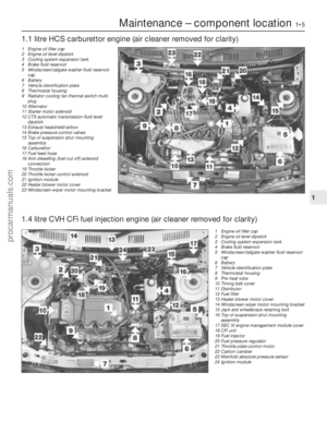 6
6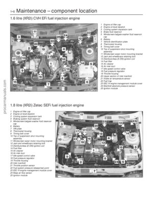 7
7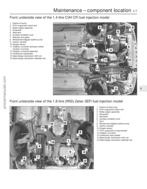 8
8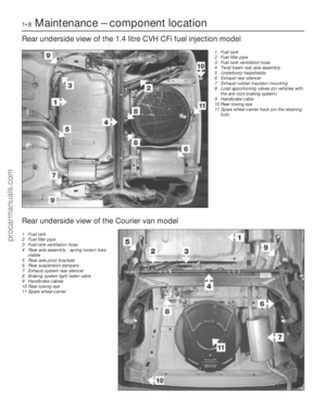 9
9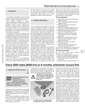 10
10 11
11 12
12 13
13 14
14 15
15 16
16 17
17 18
18 19
19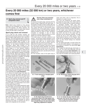 20
20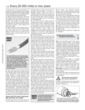 21
21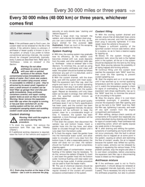 22
22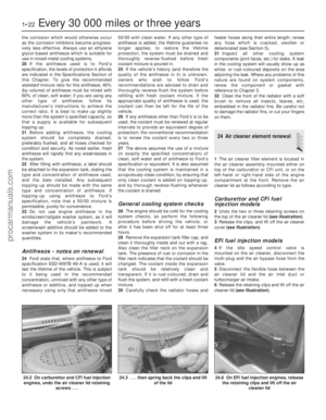 23
23 24
24 25
25 26
26 27
27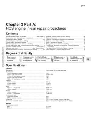 28
28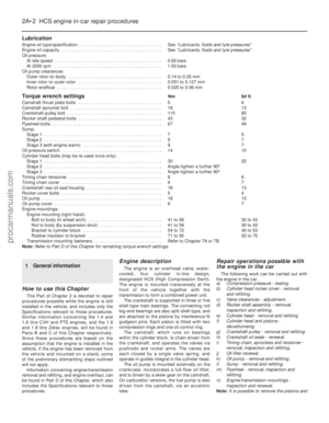 29
29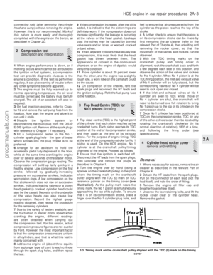 30
30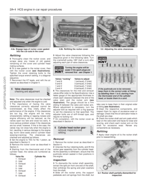 31
31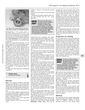 32
32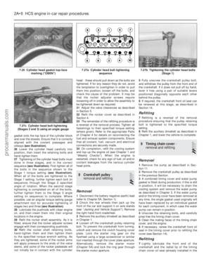 33
33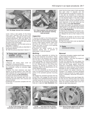 34
34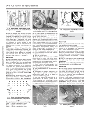 35
35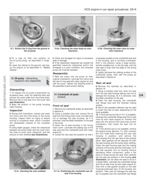 36
36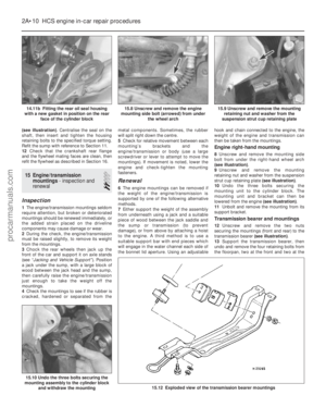 37
37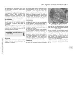 38
38 39
39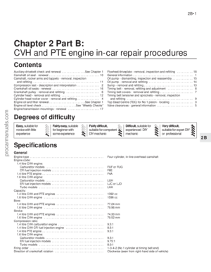 40
40 41
41 42
42 43
43 44
44 45
45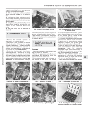 46
46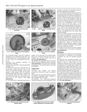 47
47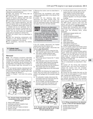 48
48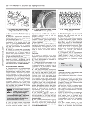 49
49 50
50 51
51 52
52 53
53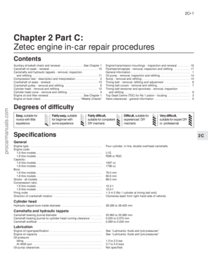 54
54 55
55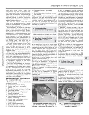 56
56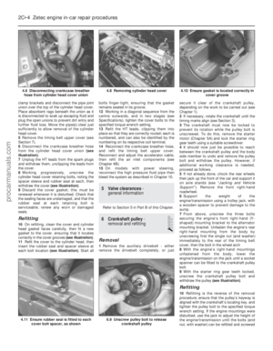 57
57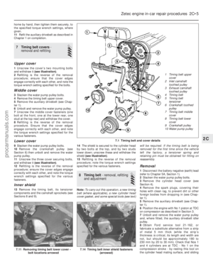 58
58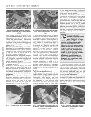 59
59 60
60 61
61 62
62 63
63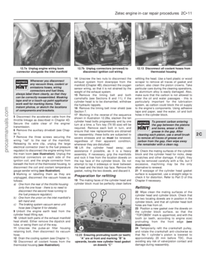 64
64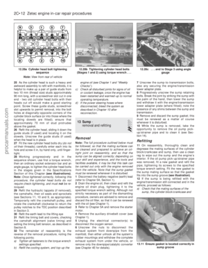 65
65 66
66 67
67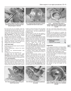 68
68 69
69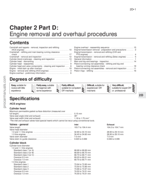 70
70 71
71 72
72 73
73 74
74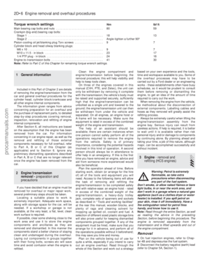 75
75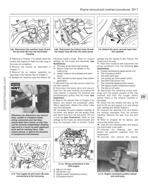 76
76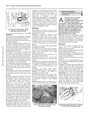 77
77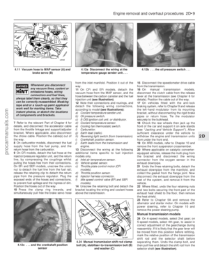 78
78 79
79 80
80 81
81 82
82 83
83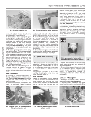 84
84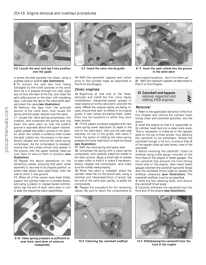 85
85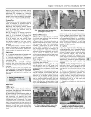 86
86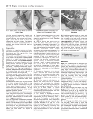 87
87 88
88 89
89 90
90 91
91 92
92 93
93 94
94 95
95 96
96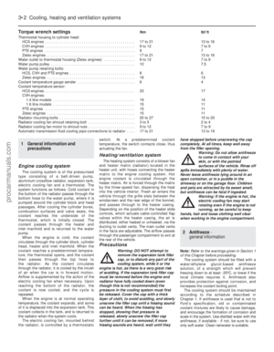 97
97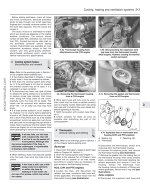 98
98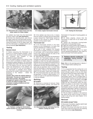 99
99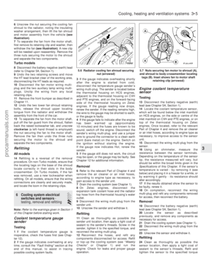 100
100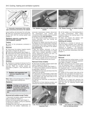 101
101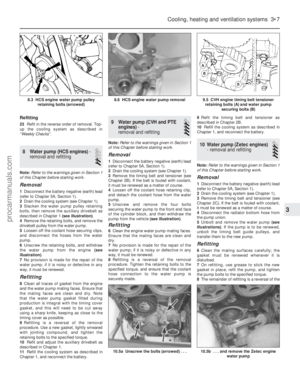 102
102 103
103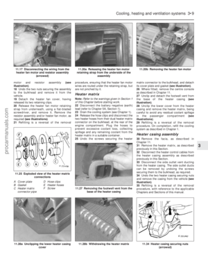 104
104 105
105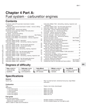 106
106 107
107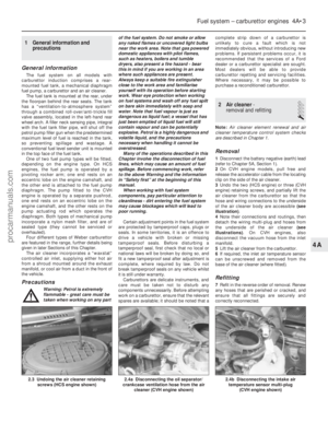 108
108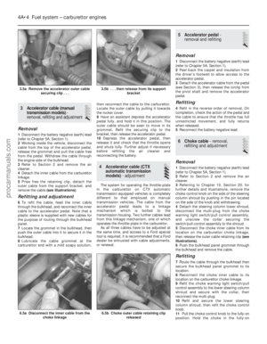 109
109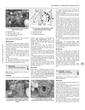 110
110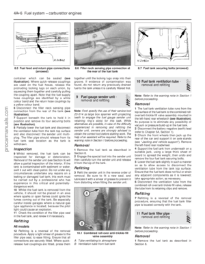 111
111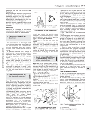 112
112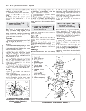 113
113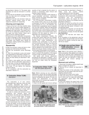 114
114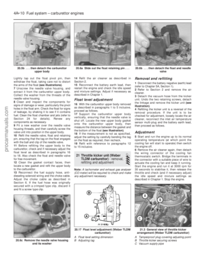 115
115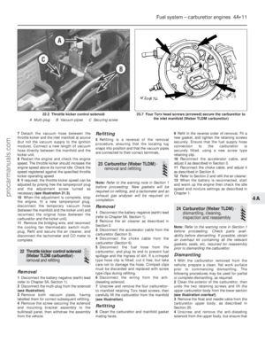 116
116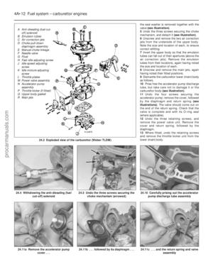 117
117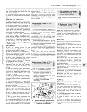 118
118 119
119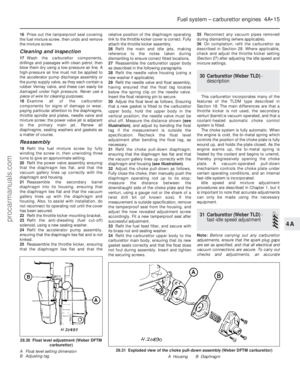 120
120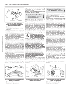 121
121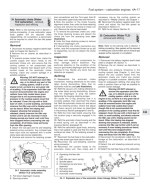 122
122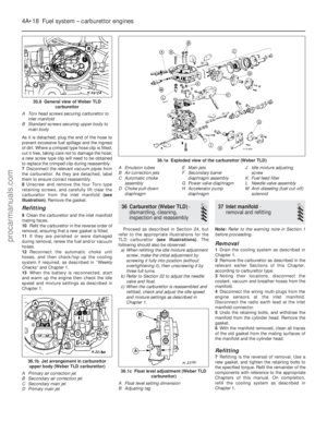 123
123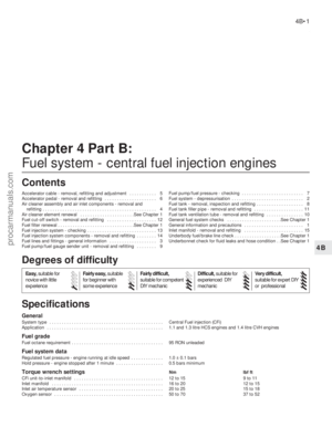 124
124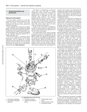 125
125 126
126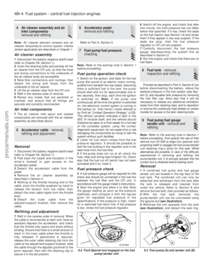 127
127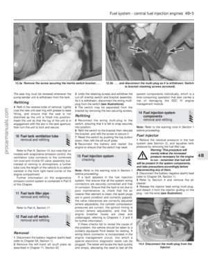 128
128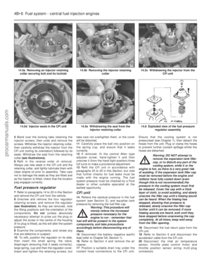 129
129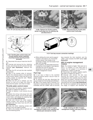 130
130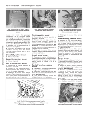 131
131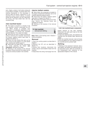 132
132 133
133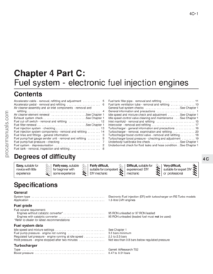 134
134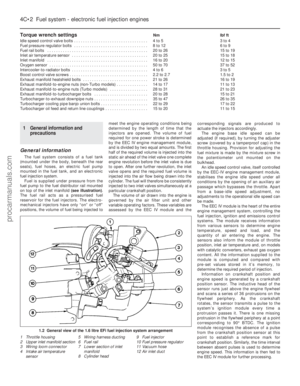 135
135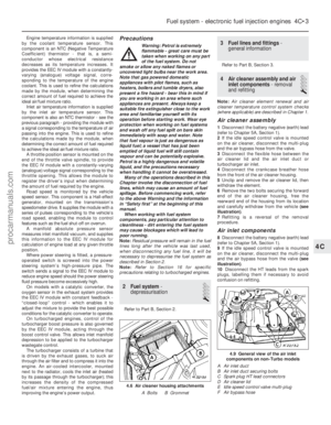 136
136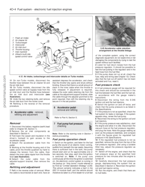 137
137 138
138 139
139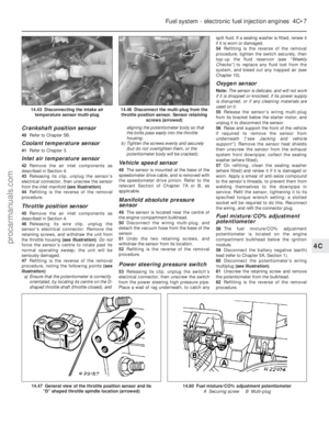 140
140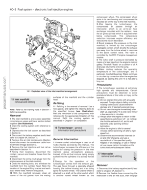 141
141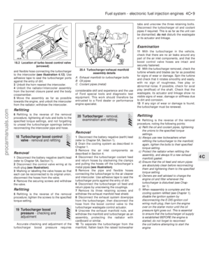 142
142 143
143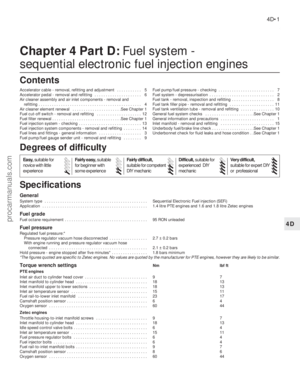 144
144 145
145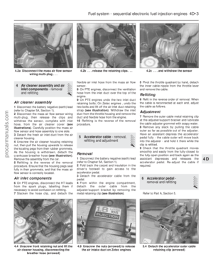 146
146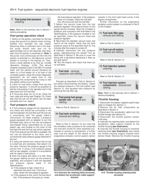 147
147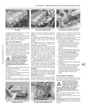 148
148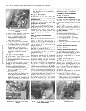 149
149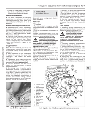 150
150 151
151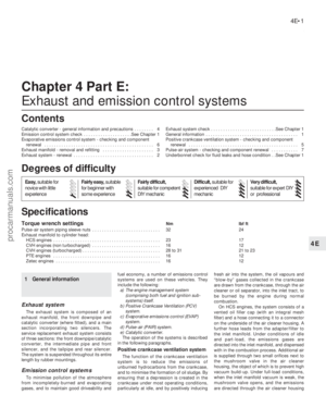 152
152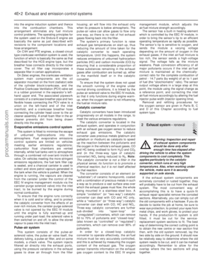 153
153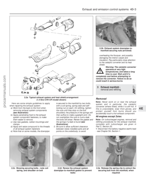 154
154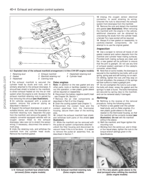 155
155 156
156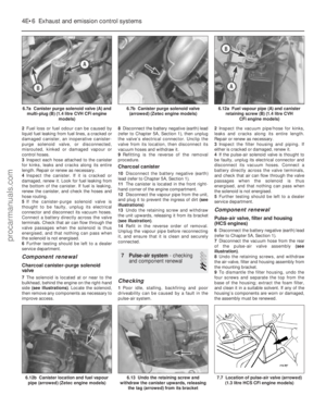 157
157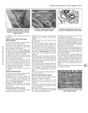 158
158 159
159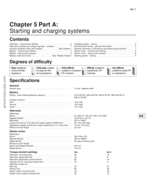 160
160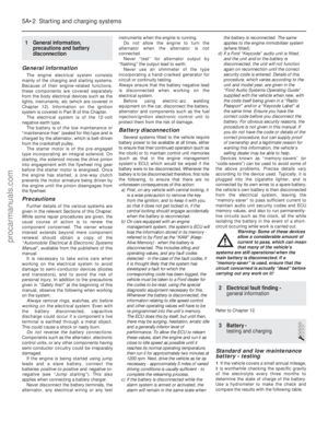 161
161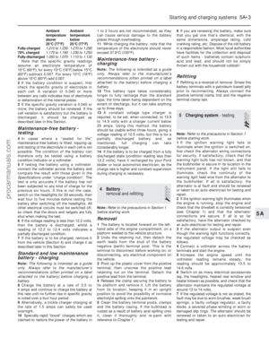 162
162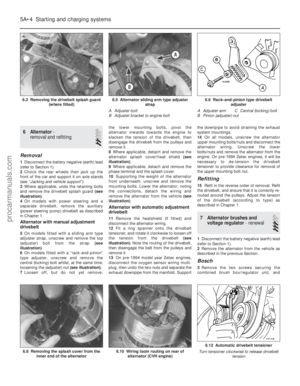 163
163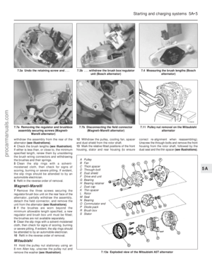 164
164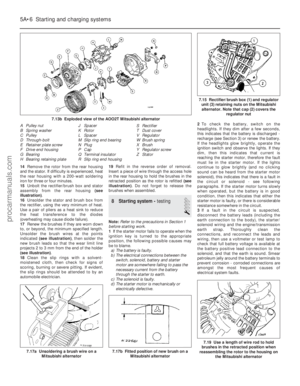 165
165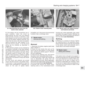 166
166 167
167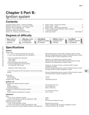 168
168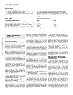 169
169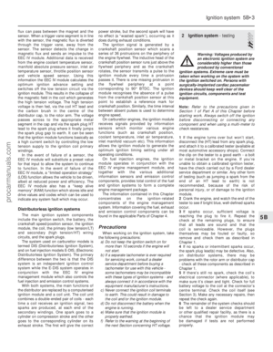 170
170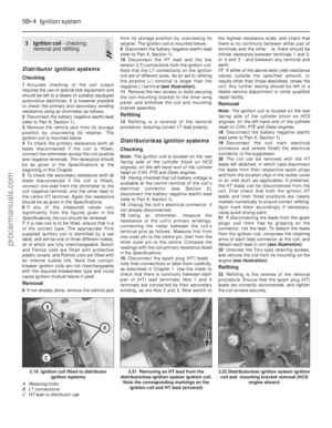 171
171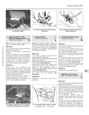 172
172 173
173 174
174 175
175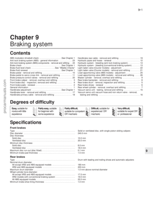 176
176 177
177 178
178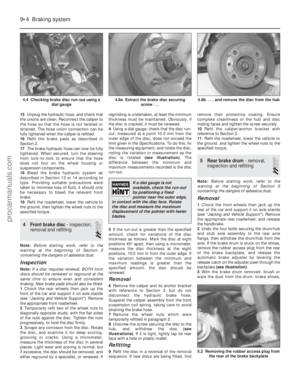 179
179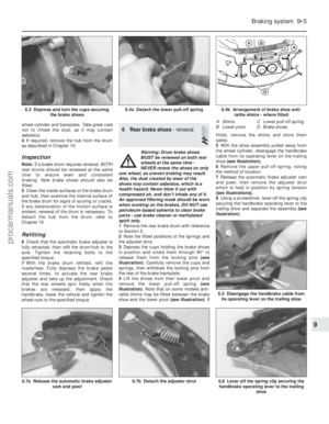 180
180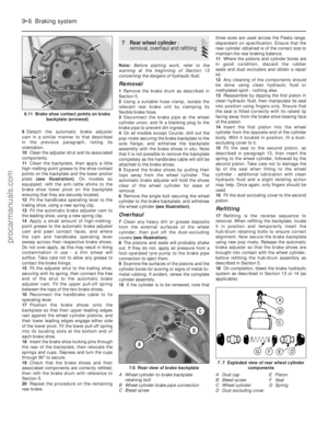 181
181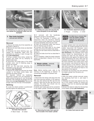 182
182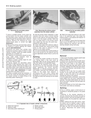 183
183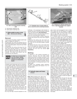 184
184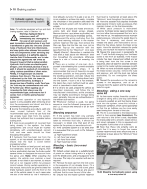 185
185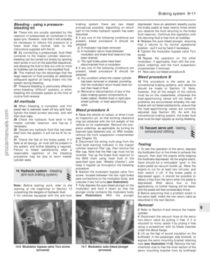 186
186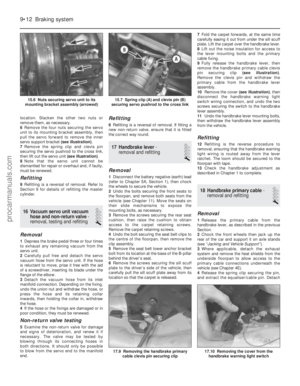 187
187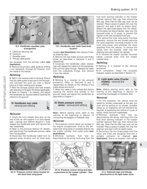 188
188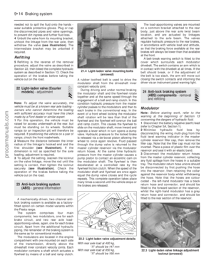 189
189 190
190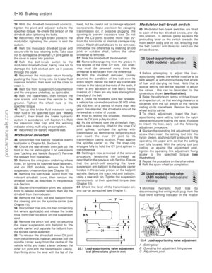 191
191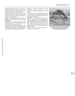 192
192 193
193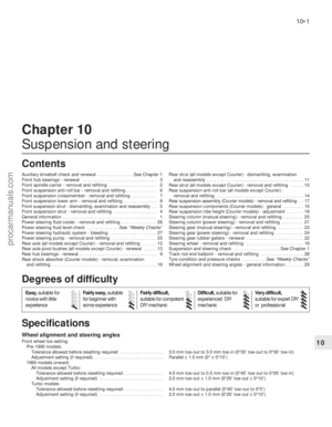 194
194 195
195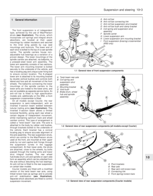 196
196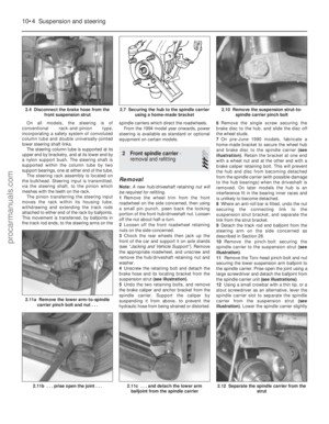 197
197 198
198 199
199 200
200 201
201 202
202 203
203 204
204 205
205 206
206 207
207 208
208 209
209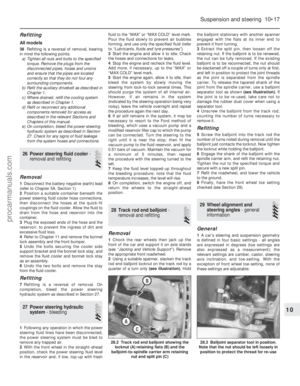 210
210 211
211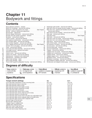 212
212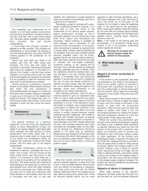 213
213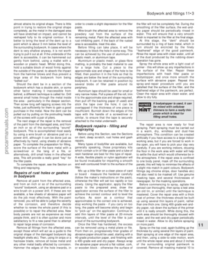 214
214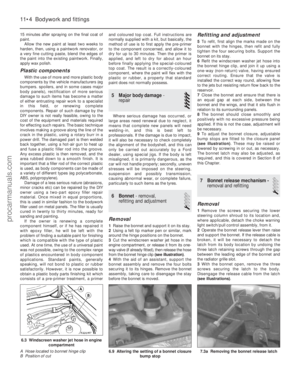 215
215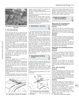 216
216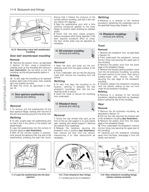 217
217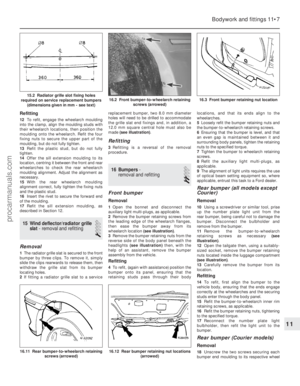 218
218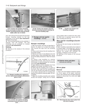 219
219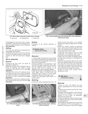 220
220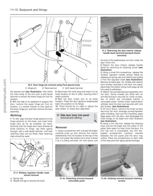 221
221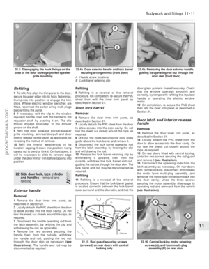 222
222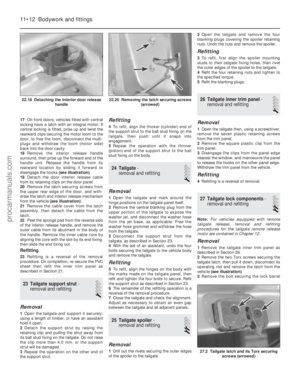 223
223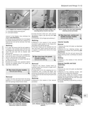 224
224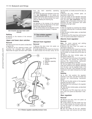 225
225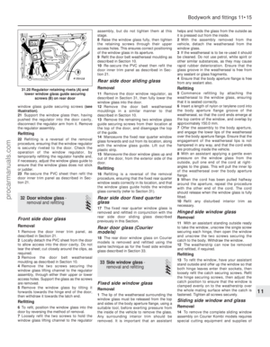 226
226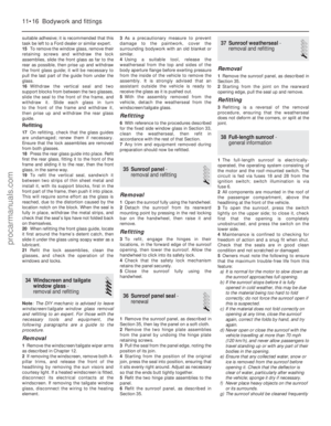 227
227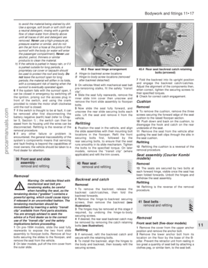 228
228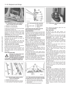 229
229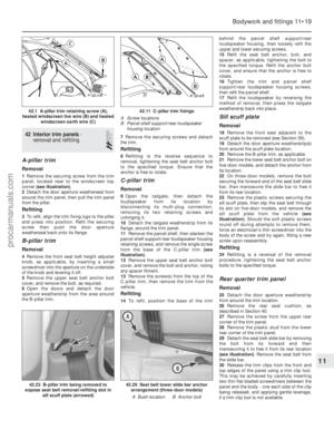 230
230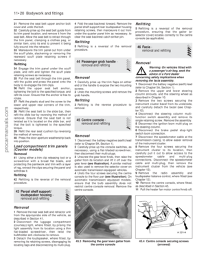 231
231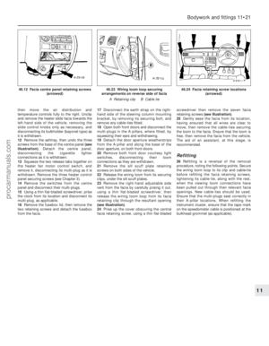 232
232 233
233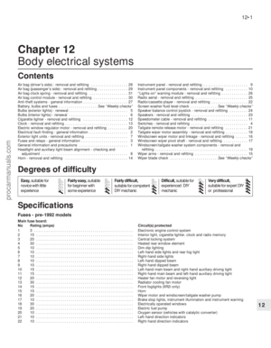 234
234 235
235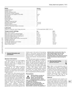 236
236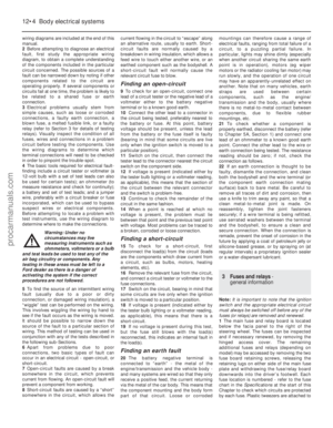 237
237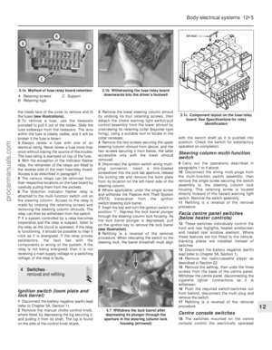 238
238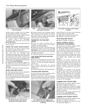 239
239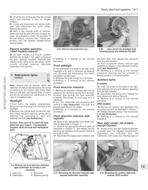 240
240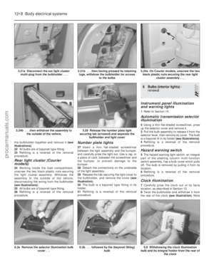 241
241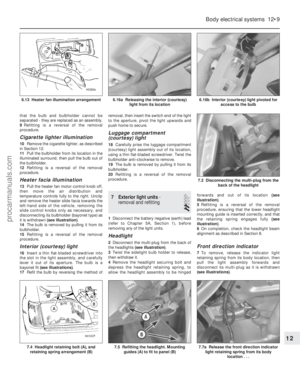 242
242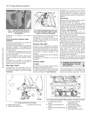 243
243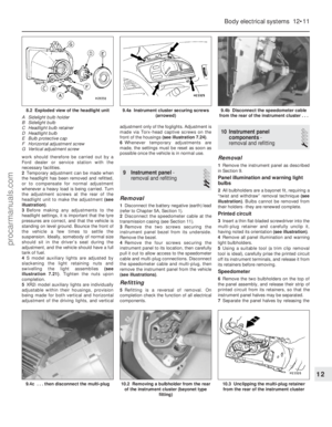 244
244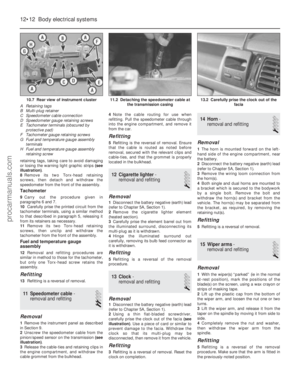 245
245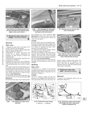 246
246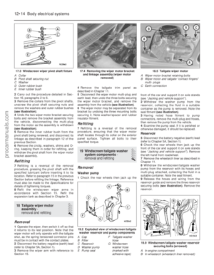 247
247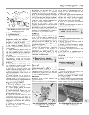 248
248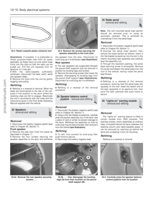 249
249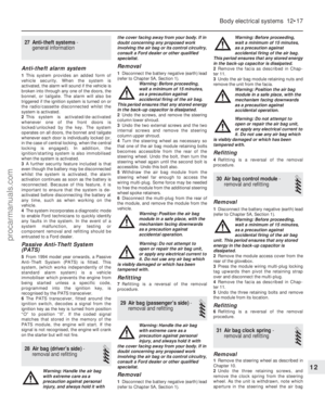 250
250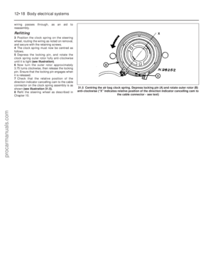 251
251 252
252 253
253 254
254 255
255 256
256 257
257 258
258 259
259 260
260 261
261 262
262 263
263 264
264 265
265 266
266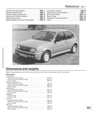 267
267 268
268 269
269 270
270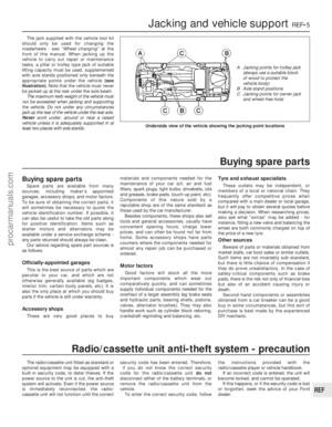 271
271 272
272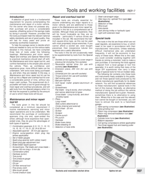 273
273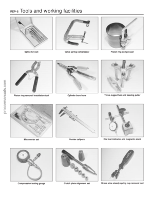 274
274 275
275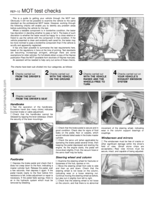 276
276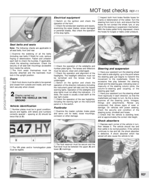 277
277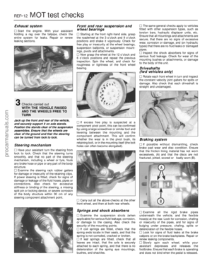 278
278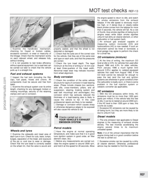 279
279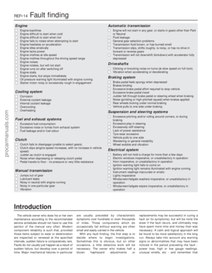 280
280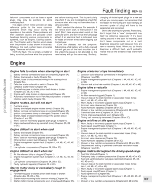 281
281 282
282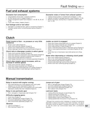 283
283 284
284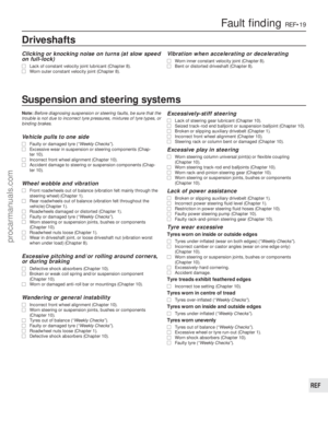 285
285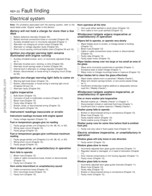 286
286 287
287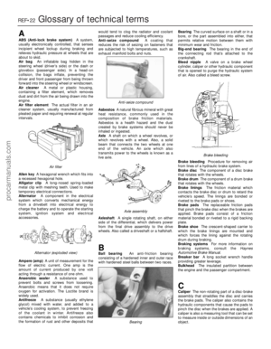 288
288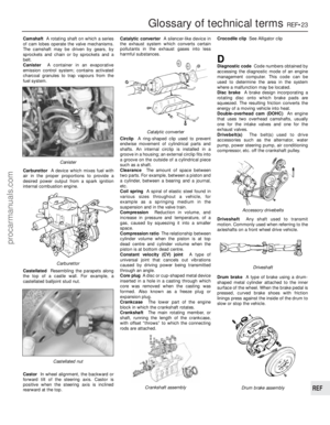 289
289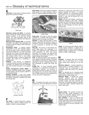 290
290 291
291 292
292 293
293 294
294 295
295