Page 9 of 296
1•8Maintenance – component location
1595Ford Fiesta Remake
Rear underside view of the 1.4 litre CVH CFi fuel injection model
1 Fuel tank
2 Fuel filler pipe
3 Fuel tank ventilation hose
4 Twist beam rear axle assembly
5 Underbody heatshields
6 Exhaust rear silencer
7 Exhaust rubber insulator mounting
8 Load apportioning valves (on vehicles withthe anti-lock braking system)
9 Handbrake cable
10 Rear towing eye
11 Spare wheel carrier hook (on the retaining
bolt)
Rear underside view of the Courier van model
1 Fuel tank
2 Fuel filler pipe
3 Fuel tank ventilation hose
4 Rear axle assembly - spring torsion bars
visible
5 Rear axle pivot brackets
6 Rear suspension dampers
7 Exhaust system rear silencer
8 Braking system light-laden valve
9 Handbrake cables
10 Rear towing eye
11 Spare wheel carrier
procarmanuals.com
http://vnx.su
Page 10 of 296
 . You should also have plenty of
rags or newspapers handy, for m")
3 Engine oil and filter renewal
1
1Make sure that you have all the necessary
tools before you begin this procedure (see
illustration) . You should also have plenty of
rags or newspapers handy, for mopping up
any spills.
2 To avoid any possibility of scalding, and to
protect yourself from possible skin irritants
and other harmful contaminants in used
engine oils, it is advisable to wear gloves
when carrying out this work. 3
Access to the underside of the vehicle is
greatly improved if the vehicle can be lifted on a
hoist, driven onto ramps, or supported by axle
stands (see “Jacking and Vehicle Support” ).
Warning: Do not work under a
vehicle which is supported only
by an hydraulic or scissors-type
jack, or by bricks, blocks of
wood, etc. 4
If this is your first oil change, get under the
vehicle and familiarise yourself with the
position of the engine oil drain plug location in
the sump. The engine and exhaust
components will be warm during the actual
work, so try to anticipate any potential
problems while the engine and accessories
are cool.
5 The oil should preferably be changed when
the engine is still fully warmed-up to normal
operating temperature, just after a run (the
needle on the temperature gauge should be in
the “Normal” sector of the gauge); warm oil
and sludge will flow out more easily. Park the
vehicle on firm, level ground, apply the
handbrake firmly, then select 1st or reverse
gear (manual transmission) or the “P” position
(automatic transmission). Open the bonnet
and remove the engine oil filler cap from the
cylinder head cover, then remove the oil level
dipstick from its tube (see “Weekly Checks”).
6 Raise the front of the vehicle, and support it
securely on axle stands (see “Jacking and
Vehicle Support” ). Remove the front right-
hand roadwheel to provide access to the oil
1 Introduction
This Chapter is designed to help the home
mechanic maintain his/her vehicle for safety,
economy, long life and peak performance.
This Chapter contains a master
maintenance schedule, followed by Sections
dealing specifically with each task in the
schedule. Visual checks, adjustments,
component renewal and other helpful items
are included. Refer to the accompanying
illustrations of the engine compartment and
the underside of the vehicle for the locations
of the various components.
Servicing your vehicle in accordance with
the mileage/time maintenance schedule and
the following Sections will provide a planned
maintenance programme, which should result
in a long and reliable service life. This is a
comprehensive plan, so maintaining some
items but not others at the specified service
intervals will not produce the same results. As you service your vehicle, you will
discover that many of the procedures can -
and should - be grouped together, because of
the particular procedure being performed, or
because of the close proximity of two
otherwise-unrelated components to one
another. For example, if the vehicle is raised
for any reason, the exhaust should be
inspected at the same time as the suspension
and steering components.
The first step of this maintenance
programme is to prepare yourself before the
actual work begins. Read through all the Sections relevant to the work to be carried
out, then make a list and gather together all
the parts and tools required. If a problem is
encountered, seek advice from a parts
specialist or a dealer service department.
2 Intensive maintenance
1
If, from the time the vehicle is new, the
routine maintenance schedule is followed
closely, and frequent checks are made of fluid
levels and high-wear items, as suggested
throughout this manual, the engine will be
kept in relatively good running condition, and
the need for additional work will be minimised.
2 It is possible that there will be some times
when the engine is running poorly due to the
lack of regular maintenance. This is even more
likely if a used vehicle, which has not received
regular and frequent maintenance checks, is
purchased. In such cases, additional work
may need to be carried out, outside of the
regular maintenance intervals.
3 If engine wear is suspected, a compression
test (refer to Part A, B or C of Chapter 2) will
provide valuable information regarding the
overall performance of the main internal
components. Such a test can be used as a
basis to decide on the extent of the work to
be carried out. If, for example, a compression
test indicates serious internal engine wear,
conventional maintenance as described in this
Chapter will not greatly improve the
performance of the engine, and may prove a waste of time and money, unless extensive
overhaul work (Chapter 2D) is carried out first.
4
The following series of operations are those
often required to improve the performance of
a generally poor-running engine:
Primary operations
a) Clean, inspect and test the battery (See
“Weekly Checks”).
b) Check all the engine-related fluids (See
“Weekly Checks”).
c) Check the condition of the auxiliary drivebelt (Section 4).
d) Check and if necessary adjust the valve
clearances on HCS engines (Section 7).
e) Renew the spark plugs and clean and inspect the HT leads (Section 21).
f) Check the condition of the air cleaner filter element and renew if necessary
(Section 24).
g) Check and if necessary adjust the idle speed and mixture settings - where
applicable (Section 9).
h) Renew the fuel filter - fuel injection models (Section 30).
i) Check the condition of all hoses, and check for fluid leaks (Section 5).
5 If the above operations do not prove fully
effective, carry out the following operations:
Secondary operations
All the items listed under “Primary
operations”, plus the following: a) Check the charging system (Chapter 5A).
b) Check the ignition system (Chapter 5B).
c) Check the fuel system (Chapter 4A, 4B,
4C and 4D).
e) Renew the ignition HT leads (Section 21).
Maintenance procedures1•9
3.2 These tools are required when changing the engine oil and filter
1
1595Ford Fiesta Remake
Every 5000 miles (8000 km) or 6 months, whichever occurs first
Frequent oil changes are the
best preventive
maintenance the home
mechanic can give the
engine, because ageing oil becomes
diluted and contaminated, which leads
to premature engine wear.
procarmanuals.com
http://vnx.su
Page 11 of 296

filter; if the additional working clearance is
required, remove also the auxiliary drivebelt
cover.
7Being careful not to touch the hot exhaust
components, place the drain pan under the
drain plug, and unscrew the plug (see
illustrations) . If possible, try to keep the plug
pressed into the sump while unscrewing it by
hand the last couple of turns.
8 Allow some time for the old oil to drain,
noting that it may be necessary to reposition
the pan as the oil flow slows to a trickle.
Check the condition of the plug’s sealing
washer and renew it if worn or damaged.
When the oil has completely drained, wipe
clean the drain plug and its threads in the
sump and refit the plug, tightening it to the
specified torque wrench setting.
9 Reposition the drain pan under the oil filter
then, using a suitable filter removal tool, unscrew the oil filter from the cylinder block,
oil pump or oil filter adaptor, as applicable; be
prepared for some oil spillage
(see
illustration) . Check the old filter to make sure
that the rubber sealing ring hasn’t stuck to the
engine; if it has, carefully remove it. Withdraw
the filter through the wheel arch, taking care
to spill as little oil as possible.
10 Using a clean, lint-free rag, wipe clean the
cylinder block around the filter mounting. If
there are no specific instructions supplied
with it, fit a new oil filter as follows. Apply a
light coating of clean engine oil to the filter’s
sealing ring (see illustration) . Screw the filter
into position until it seats, then tighten it
through a further half- to three-quarters of a
turn only (see illustration) . Tighten the filter
by hand only - do not use any tools.
11 Remove the old oil and all tools from
under the vehicle, refit the roadwheel, and
lower the vehicle to the ground.
12 Refill the engine with oil, using the correct
grade and type of oil, as given in “Lubricants,
fluids and tyre pressures” . Pour in half the
specified quantity of oil first, then wait a few
minutes for the oil to run to the sump.
Continue adding oil a small quantity at a time,
until the level is up to the lower notch on the dipstick. Adding approximately 0.5 to 1.0 litre
(depending on model) will raise the level to the
dipstick’s upper notch.
13
Start the engine. The oil pressure warning
light will take a few seconds to go out while
the new filter fills with oil; do not race the
engine while the light is on. Run the engine for
a few minutes, while checking for leaks
around the oil filter seal and the drain plug.
14 Switch off the engine, and wait a few
minutes for the oil to settle in the sump once
more. With the new oil circulated and the filter
now completely full, recheck the level on the
dipstick, and add more oil as necessary.
15 Dispose of the used engine oil safely, with
reference to “General repair procedures” in
the Reference Sections of this manual.
1•10Every 5000 miles or 6 months
3.10b Fitting the new oil filter on the Zetec engine 3.10a Lubricate the filter’s sealing ring with clean engine oil before installing the filter on the engine
3.9 Removing the oil filter on the CVHengine using a strap wrench3.7b Removing the engine oil drain plug on the Zetec engine3.7a Engine oil drain plug location in thesump on HCS, CVH and PTE engines
1595Ford Fiesta Remake
Note: It is
antisocial and
illegal to dump oil
down the drain.
To find the
location of your
local oil recycling
bank, call this
number free.
As the drain plug releases
from the threads, move it
away sharply, so the stream
of oil issuing from the sump
runs into the pan, not up
your sleeve!
procarmanuals.com
http://vnx.su
Page 12 of 296

4 Auxiliary drivebelt check andrenewal
2
General
1The number of auxiliary drivebelts fitted and
their type depends on engine, and on whether
the vehicle is equipped with power steering.
The drivebelt(s) are located on the right-hand
end of the engine and will be either of the V-
belt type or the flat, multi-ribbed (or “polyvee”)
type. The belt drives the alternator, water
pump and, on CVH and Zetec engines with
power steering, the power steering pump
from the engine’s crankshaft pulley. On HCS
engines with power steering, one belt drives
the alternator and water pump and a separate
belt drives the power steering pump.
2 The good condition and proper tension of
the auxiliary drivebelt is critical to the
operation of the engine. Because of their
composition and the high stresses to which
they are subjected, drivebelts stretch and
deteriorate as they get older. They must,
therefore, be regularly inspected.
Check
3 With the engine switched off, open and
support the bonnet, then locate the auxiliary
drivebelt(s) on the right-hand end of the
engine (Be very careful, and wear protective
gloves to minimise the risk of burning your
hands on hot components, if the engine has
recently been running). For improved access,
jack up the front right-hand side of the
vehicle, support it securely on an axle
stand, remove the roadwheel, then (where
fitted) remove the auxiliary drivebelt lower
cover from inside the wheel arch (see
illustration) .
4 Using an inspection light or an electric
torch, and rotating the engine when necessary
with a spanner applied to the crankshaft
pulley bolt, check the whole length of the drivebelt(s) for cracks, separation of the
rubber, and torn or worn ribs
(see
illustration) . Also check for fraying and
glazing, which gives the drivebelt a shiny
appearance. Both sides of the drivebelt(s)
should be inspected, which means you will
have to twist the drivebelt(s) to check the
underside. Feel the relevant drivebelt where
you can’t see it. If you are in any doubt as to
the condition of the drivebelt(s), renewal is
necessary (go to paragraph 23).
Drivebelt tension
5 The tension must be adjusted manually on
all V-belt type drivebelts, on flat “polyvee”
type drivebelts fitted to early Zetec engines,
and on “polyvee” type drivebelts fitted to HCS
engines to drive the power steering pump.
The “polyvee” type drivebelts used on later
Zetec engines and PTE engines are fitted with
an automatic tensioner to maintain the correct
belt adjustment.
6 For models on which the tension can be
adjusted manually, open the bonnet. Jack up the front right-hand side of the vehicle, and
support it securely on an axle stand. Remove
the roadwheel, then (where fitted) remove the
auxiliary drivebelt lower cover from inside the
wheel arch.
7
Ford technicians use a special tension gauge
and various other special tools for checking
drivebelt adjustment, but for DIY purposes,
checking the belt tension using finger pressure
gives a good indication of correct adjustment.
Apply firm finger pressure midway between the
pulleys on the longest run of the belt, and look
for a deflection of approximately 2.0 mm (i.e. a
total drivebelt “swing” of approximately
4.0 mm) (see illustration) .
8 If adjustment is necessary, proceed as
follows according to belt type.
V-belt with sliding arm type adjuster
9 Loosen off the alternator mounting bolts
and sliding arm adjustment bolts, pivot the
alternator as required to provide the correct
drivebelt tension, then retighten the bolts to
secure (see illustration) .
10 Refit the auxiliary drivebelt cover (where
applicable) and roadwheel, then lower the
vehicle to the ground.
11 Run the engine for about five minutes,
then recheck the tension.
Every 10 000 miles (16 000 km) or 12 months,
whichever comes first
Every 10 000 miles or 12 months1•11
4.9 Alternator sliding arm adjustment
bolt (A) and sliding arm mounting bolt (B) - V-belt with sliding arm type adjuster
4.7 Checking drivebelt adjustment - V-belt types
Note that the 4 mm dimension is the total belt swing and is equal to 2 mm of deflection
4.3 Remove the auxiliary drivebelt lower cover from inside the wheel arch
1
1595Ford Fiesta Remake
4.4 Check the auxiliary drivebelt forsigns of wear like these. Very small
cracks across the drivebelt ribs are acceptable. If the cracks are deep, or if the drivebelt looks worn or
damaged in any other way, renew it. This is the “polyvee” type belt, butthe checks on the V-belt type are the same
Turning the engine will be
much easier if the spark
plugs are removed first
(Section 21).
procarmanuals.com
http://vnx.su
Page 13 of 296

V-belt and flat “polyvee” type
drivebelt with rack-and-pinion type
adjuster
12Loosen off the alternator mounting bolts
and the adjusting arm mounting bolt. Slacken
the pinion central locking bolt, and turn the
pinion nut as required to take up the tension
of the drivebelt. Hold it at the required setting,
and tighten the central bolt securely to lock
the adjuster arm and set the tension (see
illustrations) .
13 Tighten the alternator mounting and
adjusting arm bolts securely.
14 Refit the auxiliary drivebelt cover (where
applicable) and roadwheel, then lower the
vehicle to the ground.
15 Run the engine for about five minutes,
then recheck the tension.
Flat “polyvee” type drivebelt with
tensioner pulley adjuster (HCS engine
power steering pump drivebelt)
16 Slacken the tensioner pulley centre bolt
then turn the adjuster bolt at the base of the
tensioner pulley bracket, as required, to take
up the tension of the drivebelt. When the belt
deflection is correct, tighten the adjuster
pulley centre retaining bolt.
17 Refit the auxiliary drivebelt cover (where
applicable) and roadwheel, then lower the
vehicle to the ground.
18 Run the engine for about five minutes,
then recheck the tension.
Flat “polyvee” type drivebelt with
automatic adjuster
19 As mentioned above, this type of drivebelt
is tensioned by an automatic tensioner;
regular checks are not required, and manual
“adjustment” is not possible.
20 If you suspect that the drivebelt is slipping
and/or running slack, or that the tensioner is
otherwise faulty, it must be renewed. To do
this, remove the drivebelt as described below,
then unbolt and remove the tensioner. On
fitting the new tensioner, ensure that it is
aligned correctly on its mountings, and
tightened to the specified torque wrench
setting.
Renewal
21 Open the bonnet. Jack up the front right-
hand side of the vehicle, and support it
securely on an axle stand. Remove the
roadwheel, then remove the auxiliary drivebelt
lower cover (where fitted) from inside the
wheel arch.
22 The routing of the drivebelt around the
pulleys is dependent on the drivebelt type,
and on whether power steering is fitted.
Before removing the drivebelt, it’s a good idea
to sketch the belt run around the pulleys; this
will save a lot of frustration when it comes to
refitting. Note that on HCS engines with
power steering, to renew the alternator/
water pump drivebelt it will be necessary to
remove the power steering pump drivebelt
first.
23 If the existing drivebelt is to be refitted,
mark it, or note the maker’s markings on its
flat surface, so that it can be installed the
same way round.
24 To renew a drivebelt with manual
adjustment, slacken the belt tension fully as
described above, according to type. Slip the
belt off the pulleys, then fit the new belt,
ensuring that it is routed correctly. If fitting a
flat “polyvee” type drivebelt, arrange it on the
grooved pulleys so that it is centred in
their grooves, and not overlapping their raised
sides. With the belt in position, adjust the
tension as previously described.
25 To renew the flat, “polyvee” type drivebelt
with automatic adjuster, reach up between
the body and the engine (above the
crankshaft pulley), and apply a spanner to the
hexagon in the centre of the automatic
tensioner’s pulley. Rotate the tensioner pulley
clockwise to release its pressure on the
drivebelt, then slip the drivebelt off the
crankshaft pulley, and release the tensioner
again (see illustration) . Note that on certain
models, a self-cocking tensioner is fitted, and
that this will remain in the released position.
Working from the wheel arch or engine
compartment as necessary, and noting its
routing, slip the drivebelt off the remaining
pulleys and withdraw it.
26 Check all the pulleys, ensuring that their
grooves are clean, and removing all traces of oil and grease. Check that the tensioner
works properly, with strong spring pressure
being felt when its pulley is rotated clockwise,
and a smooth return to the limit of its travel
when released.
27
If the original drivebelt is being refitted,
use the marks or notes made on removal, to
ensure that it is installed to run in the same
direction as it was previously. To fit the
drivebelt, arrange it on the grooved pulleys so
that it is centred in their grooves, and not
overlapping their raised sides, and is routed
correctly. Start at the top, and work down to
finish at the crankshaft pulley; rotate the
tensioner pulley clockwise, slip the drivebelt
onto the crankshaft pulley, then release the
tensioner again.
28 Using a spanner applied to the crankshaft
pulley bolt, rotate the crankshaft through at
least two full turns clockwise to settle the
drivebelt on the pulleys, then check that
the drivebelt is properly installed.
29 Refit the auxiliary drivebelt cover (where
applicable) and roadwheel, then lower the
vehicle to the ground.
5 Underbonnet check for fluid leaks and hose condition
1
General
1High temperatures in the engine
compartment can cause the deterioration of
the rubber and plastic hoses used for engine,
accessory and emissions systems operation.
Periodic inspection should be made for
cracks, loose clamps, material hardening and
leaks.
2 Carefully check the large top and bottom
radiator hoses, along with the other smaller-
diameter cooling system hoses and metal
pipes; do not forget the heater hoses/pipes
which run from the engine to the bulkhead.
Inspect each hose along its entire length,
replacing any that is cracked, swollen or
shows signs of deterioration. Cracks may
become more apparent if the hose is
1•12Every 10 000 miles or 12 months
4.25 Automatic drivebelt tensioner - “polyvee” type drivebelt
Turn tensioner clockwise to release tension4.12b When the tension is correct, hold
the adjuster nut, and tighten the central bolt securely to lock the adjuster arm4.12a Rack-and-pinion type auxiliary drivebelt adjuster
A Adjuster arm
B Pinion (adjuster) nut
C Central (locking) bolt
1595Ford Fiesta Remakeprocarmanuals.com
http://vnx.su
Page 14 of 296
 . If you are using
non-Ford specification antifreeze, and so
have to renew the coolant every two years or
so, it’s a good idea to renew the hoses at that
time, regardless")
squeezed (see illustration) . If you are using
non-Ford specification antifreeze, and so
have to renew the coolant every two years or
so, it’s a good idea to renew the hoses at that
time, regardless of their apparent condition.
3 Make sure that all hose connections are
tight. A leak in the cooling system will usually
show up as white- or rust-coloured deposits
on the areas adjoining the leak; if the spring
clamps that are used to secure the hoses in
this system appear to be slackening, they
should be renewed to prevent the possibility
of leaks.
4 Some other hoses are secured to their
fittings with clamps. Where clamps are used,
check to be sure they haven’t lost their
tension, allowing the hose to leak. If clamps
aren’t used, make sure the hose has not
expanded and/or hardened where it slips over
the fitting, allowing it to leak.
5 Check all fluid reservoirs, filler caps, drain
plugs and fittings etc, looking for any signs
of leakage of oil, transmission and/or brake
hydraulic fluid, coolant and power steering
fluid. If the vehicle is regularly parked in the
same place, close inspection of the ground
underneath it will soon show any leaks. As
soon as a leak is detected, its source must
be traced and rectified. Where oil has been
leaking for some time, it is usually necessary
to use a steam cleaner, pressure washer or
similar, to clean away the accumulated
dirt, so that (when the engine is run again)
the exact source of the leak can be
identified.
Vacuum hoses
6 It’s quite common for vacuum hoses,
especially those in the emissions system, to be
colour-coded, or to be identified by coloured stripes moulded into them. Various systems
require hoses with different wall thicknesses,
collapse resistance and temperature
resistance. When renewing hoses, be sure the
new ones are made of the same material.
7
Often the only effective way to check a
hose is to remove it completely from the
vehicle. If more than one hose is removed, be
sure to label the hoses and fittings to ensure
correct installation.
8 When checking vacuum hoses, be sure to
include any plastic T-fittings in the check.
Inspect the fittings for cracks, and check the
hose where it fits over the fitting for distortion,
which could cause leakage.
9 A small piece of vacuum hose (quarter-inch
inside diameter) can be used as a
stethoscope to detect vacuum leaks. Hold
one end of the hose to your ear, and probe
around vacuum hoses and fittings, listening
for the “hissing” sound characteristic of a
vacuum leak. Warning: When probing with the
vacuum-hose stethoscope, be
very careful not to come into
contact with moving engine
components such as the auxiliary
drivebelt, radiator electric cooling fan, etc.
Fuel hoses
Warning: There are certain
precautions which must be
taken when inspecting or
servicing fuel system
components. Work in a well-ventilated
area, and do not allow open flames
(cigarettes, appliance pilot lights, etc.) or
bare light bulbs near the work area. Mop
up any spills immediately, and do not store
fuel-soaked rags where they could ignite.
10 Check all fuel hoses for deterioration and
chafing. Check especially for cracks in areas
where the hose bends, and also just before
fittings, such as where a hose attaches to the
fuel filter.
11 High-quality fuel line, usually identified by
the word “Fluoroelastomer” printed on the
hose, should be used for fuel line renewal.
Never, under any circumstances, use
unreinforced vacuum line, clear plastic tubing
or water hose for fuel lines.
12 Spring- type clamps are commonly used
on fuel lines. These clamps often lose their
tension over a period of time, and can be
“sprung” during removal. Replace all
spring- type clamps with screw clamps
whenever a hose is replaced.
Metal lines
13 Sections of metal piping are often used
for fuel line between the fuel filter and the
engine. Check carefully to be sure the piping
has not been bent or crimped, and that cracks
have not started in the line.
14 If a section of metal fuel line must be
renewed, only seamless steel piping should
be used, since copper and aluminium piping
don’t have the strength necessary to
withstand normal engine vibration. 15
Check the metal brake lines where they
enter the master cylinder and ABS hydraulic
unit (if used) for cracks in the lines or loose
fittings. Any sign of brake fluid leakage calls
for an immediate and thorough inspection of
the brake system.
6 Engine compartment wiring check
1
1With the vehicle parked on level ground,
apply the handbrake firmly and open the
bonnet. Using an inspection light or a small
electric torch, check all visible wiring within
and beneath the engine compartment.
2 What you are looking for is wiring that is
obviously damaged by chafing against sharp
edges, or against moving suspension/
transmission components and/or the auxiliary
drivebelt, by being trapped or crushed
between carelessly-refitted components, or
melted by being forced into contact with the
hot engine castings, coolant pipes, etc. In
almost all cases, damage of this sort is
caused in the first instance by incorrect
routing on reassembly, after previous work
has been carried out.
3 Depending on the extent of the problem,
damaged wiring may be repaired by rejoining
the break or splicing-in a new length of wire,
using solder to ensure a good connection,
and remaking the insulation with adhesive
insulating tape or heat-shrink tubing, as
appropriate. If the damage is extensive, given
the implications for the vehicle’s future
reliability, the best long-term answer may well
be to renew that entire section of the loom,
however expensive this may appear.
4 When the actual damage has been
repaired, ensure that the wiring loom is re-
routed correctly, so that it is clear of other
components, and not stretched or kinked, and
is secured out of harm’s way using the plastic
clips, guides and ties provided.
5 Check all electrical connectors, ensuring
that they are clean, securely fastened, and
that each is locked by its plastic tabs or wire
clip, as appropriate. If any connector shows
external signs of corrosion (accumulations of
white or green deposits, or streaks of “rust”),
or if any is thought to be dirty, it must be
unplugged and cleaned using electrical
contact cleaner. If the connector pins are
severely corroded, the connector must be
renewed; note that this may mean the renewal
of that entire section of the loom - see your
local Ford dealer for details.
6 If the cleaner completely removes the
corrosion to leave the connector in a
satisfactory condition, it would be wise to
pack the connector with a suitable material
which will exclude dirt and moisture,
preventing the corrosion from occurring
again; a Ford dealer may be able to
recommend a suitable product.
7 Check the condition of the battery
Every 10 000 miles or 12 months1•13
5.2 Hoses, like drivebelts, have a habit of
failing at the worst possible time - to
prevent the inconvenience of a blown radiator or heater hose, inspect them
carefully as shown here
1
1595Ford Fiesta Remakeprocarmanuals.com
http://vnx.su
Page 15 of 296

connections - remake the connections or
renew the leads if a fault is found. Use the
same techniques to ensure that all earth
points in the engine compartment provide
good electrical contact through clean, metal-
to-metal joints, and that all are securely
fastened. (In addition to the earth connection
at the engine lifting eye, and that from the
transmission to the body/battery, there are
others in various places, so check carefully).
8Refer to Section 21 for details of spark plug
(HT) lead checks.
7 Valve clearance adjustment
2
Refer to Chapter 2, Part A.
8 Manual transmission oil level check
1
1The manual transmission does not have a
dipstick. To check the oil level, raise the
vehicle and support it securely on axle stands,
making sure that the vehicle is level. On the
lower front side of the transmission housing,
you will see the filler/level plug. Unscrew and
remove it - an Allen key or bit will probably be
required (see illustration) .
2 With the plug removed, check the oil level.
To do this accurately, make up an oil level
check dipstick from a short length of welding
rod or similar material. Make a 90º bend in the
rod, then mark the downward leg in 5 mm
increments. The dipstick is then inserted
through the filler plug orifice so that the
unmarked leg rests flat on the plug orifice
threads, with the marked leg dipped in the oil.
Withdraw the dipstick and read off the level of
oil.
3 The oil level must be maintained between 0
and 5 mm below the lower edge of the
filler/level plug hole. Top up (if necessary),
using fresh transmission oil of the specified
type and using a syringe, or a plastic bottle
and tube. Refit and tighten the filler/level plug
to the specified torque on completion. 4
The need for regular topping-up can only
be due to a leak, which should be found and
rectified without delay.
5 Regular oil changing is not specified by the
manufacturer’s, but the oil can be drained, if
required, by removing the selector shaft cap
nut and locking assembly.
9 Idle speed and mixture check and adjustment
4
General
1Many of the engines fitted to Fiesta models
are equipped with fuel injection systems of
one sort or another which are entirely
controlled by the engine management system.
On most of these vehicles, it isn’t possible to
make any adjustments to the idle speed or the
mixture settings without specialist test
equipment of a type usually only found at a
Ford dealer or fuel injection specialist.
However, the very nature of these highly-
sophisticated systems means they don’t go
out of tune very often (if ever), so that it’s one
less maintenance operation to worry about.
2 On carburettor engines and 1.6 litre EFi fuel
injection engines, certain checks and
adjustments are necessary as part of the
service requirements, and these are described
below.
Idle speed and mixture check
and adjustment - carburettor
engines
Note: Later carburettors are fitted with
tamperproof mixture adjusting screws,
consisting of a hexagon-shaped socket with a
pin in the centre. Such screws require the use
of Ford service tool 23-032 to alter their
settings; if this tool (or a suitable equivalent) is
not available, the CO level will have to be
checked, and any necessary adjustment will
have to be made, by a Ford dealer.
3 Before carrying out the following checks
and adjustments, ensure that the spark plugs
are in good condition and correctly gapped
(Section 21). To carry out the checks/adjustments, an accurate tachometer
and an exhaust gas analyser (CO meter) will
be required.
4
Make sure that all electrical components
are switched off during the following
procedures.
5 Connect a tachometer to the engine in
accordance with its manufacturer’s
instructions, and insert the probe of an
exhaust gas analyser (CO meter) into the
exhaust tailpipe. As previously mentioned,
these items are essential in obtaining an
accurate setting. If they are not available, an
approximate check/adjustment can be made
as a temporary measure, providing they are
further checked out as soon as is possible
using a tachometer and a CO meter (or by a
Ford dealer).
6 Run the engine at a fast idle speed until it
reaches its normal operating temperature and
the radiator cooling fan cuts in. Turn the
engine off, then disconnect the radiator
cooling fan lead at the thermostatic switch
connector. Now connect a temporary wire to
the fan switch multi-plug, as shown (see
illustration) to enable the fan to operate
continuously during the following checks and
adjustments (if this is specified). Take care to
keep clear of the fan during the following
operations when working in the engine
compartment.
7 Where fitted, disconnect the throttle kicker
vacuum pipe, and plug the end. To identify
the throttle kicker unit, refer to Chapter 4A.
8 Check that the vehicle lighting and other
electrical loadings (apart from the radiator
cooling fan) are switched off, then restart the
engine. Increase the engine speed to 3000 rpm
for 30 seconds, and repeat this at three-minute
intervals during the check/adjustment
procedures. This will ensure that any excess
fuel is cleared from the inlet manifold.
9 Ensure that the throttle is fully released, allow
the meters to stabilise for a period of 5 to
30 seconds is normally sufficient, then check
the idle speed against that specified. If adjust-
ment is necessary, turn the idle speed
adjusting screw until the engine is idling at the
specified speed (see illustrations) . Any checks
and adjustments must be completed within
30 seconds of the meters stabilising.
1•14Every 10 000 miles or 12 months
9.9a Idle speed adjusting screw (A) and
mixture adjusting screw (B) (Weber TLM
carburettor)9.6 Cooling fan thermostatic switch multi-plug with temporary bridging wire
connected8.1 Manual transmission oil level/filler
plug (A), and selector shaft cap nut (B)
1595Ford Fiesta Remakeprocarmanuals.com
http://vnx.su
Page 16 of 296

10If adjustment to the mixture is required,
the tamperproof cap will need to be removed
from the carburettor to gain access to the
mixture screw. To do this, first unclip the fuel
trap from the side of the air cleaner unit, then
remove the air cleaner unit, ensuring that the
crankcase ventilation trap remains connected.
Prise free the tamperproof cap (with the aid of
a thin-bladed screwdriver), then with the
vacuum and emissions control pipes
connected to it, relocate the air cleaner unit
temporarily into position.
11 Turn the mixture adjustment screw
clockwise to weaken the mixture, or
anti-clockwise to richen it, until the CO
reading is as given in the Specifications. If a
CO meter is not being used, weaken the
mixture as described, then enrich the mixture until the maximum engine speed is obtained,
consistent with even running.
12
If necessary, re-adjust the idle speed then
check the CO reading again. Repeat as
necessary until both the idle speed and CO
reading are correct.
13 Where required by law (as in some
European countries), fit a new tamperproof
cap to the mixture adjustment screw.
14 Disconnect the tachometer and the CO
meter, refit the air cleaner unit, and reconnect
the fan switch lead to complete.
Base idle speed and mixture
check and adjustment - 1.6 litre
EFi engines
15 Proceed as described above in
paragraphs 3 to 6 inclusive, then continue as
follows.
16 Run the engine at a fast idle speed until it
reaches its normal operating temperature and
the cooling fan cuts in. Check the CO content
of the exhaust, and compare it against the
specified reading. If the CO content reading is
incorrect, it can be adjusted by prising free
the tamperproof cap for access to the mixture
CO adjustment screw (see illustration), and
turning the screw in the required direction to
suit.
17 The operational idle speed is controlled by
the EEC IV engine management module and is
not adjustable. However, if the base idle
speed is incorrect, the module will not have an
accurate datum point from which to establish the normal operational idle speed. If idle
problems have been experienced, the base
idle speed should be checked as follows.
18
Disconnect the multi-plug from the idle
speed control valve and increase the engine
speed to 2000 rpm, hold it at that speed for
30 seconds, then fully release the throttle and
check if the base idle speed registered is as
specified.
19 If adjustment is necessary, prise free the
tamperproof plug using a suitable small
screwdriver to gain access to the base idle
speed adjustment screw in the throttle body.
Turn the screw in the required direction to
adjust the base idle speed to the specified
amount. Turning the screw anti-clockwise
increases the idle speed (see illustration).
20 Increase the engine speed to 2000 rpm
again, hold it at that speed for 30 seconds,
then fully release the throttle once more.
Check and further adjust the base idle speed
if required, then fit a new tamperproof plug
into position.
21 Reconnect the idle speed control valve
multi-plug and check that the engine speed
briefly rises to about 900 rpm, then drops
down to the specified normal idle speed.
22 On completion, disconnect the
tachometer and the CO meter, but continue
running the engine at idle speed for a period
of about five minutes, to enable the engine
management module to relearn its values
before switching it off.
10 Steering, suspension and roadwheel check
2
Front suspension and steering
check
1Chock the rear wheels then jack up the
front of the car and support it on axle stands
(see “Jacking and Vehicle Support” ).
2 Visually inspect the balljoint dust covers
and the steering gear gaiters for splits, chafing
or deterioration (see illustrations) . Any wear
of these components will cause loss of
Every 10 000 miles or 12 months1•15
9.9d Idle speed mixture adjusting
screw (A) and idle speed adjusting screw (B) (Weber TLD carburettor)9.9c Idle speed mixture adjusting
screw (A) and idle speed adjusting screw (B) (Weber DFTM carburettor)9.9b Idle speed adjusting screw (A) and
mixture adjusting screw (B) (Weber TLDM carburettor)
10.2a Check the condition of the track rodend balljoint dust cover (arrowed)9.19 Base idle speed adjustment screw(arrowed) on the 1.6 litre EFi engine
9.16 Adjusting the idle mixture CO content on the 1.6 litre EFi engine
1
1595Ford Fiesta Remakeprocarmanuals.com
http://vnx.su
 1
1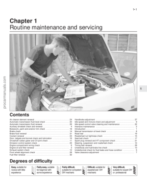 2
2 3
3 4
4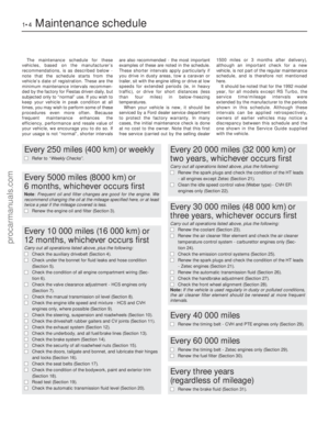 5
5 6
6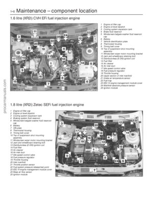 7
7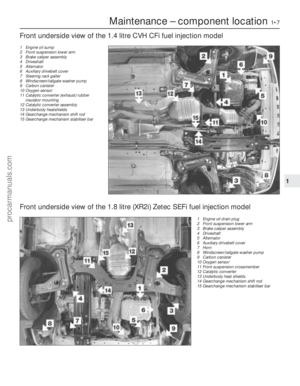 8
8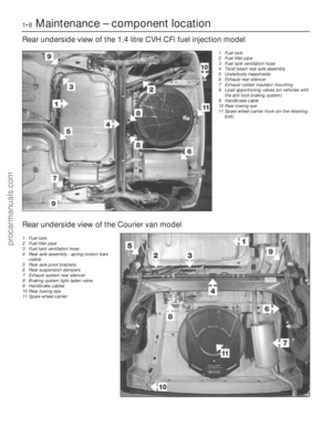 9
9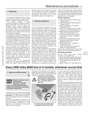 10
10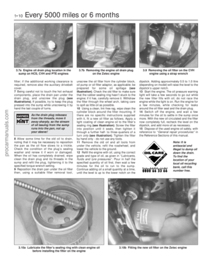 11
11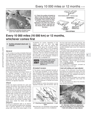 12
12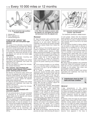 13
13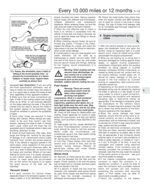 14
14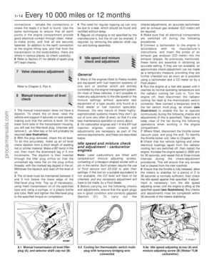 15
15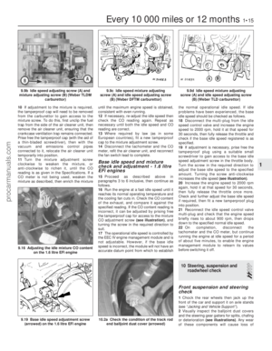 16
16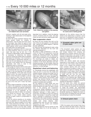 17
17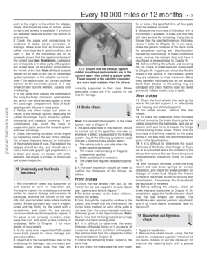 18
18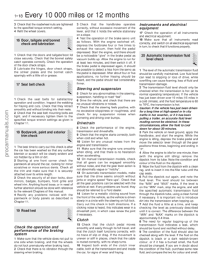 19
19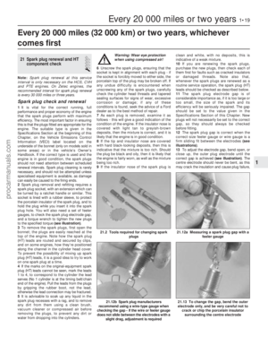 20
20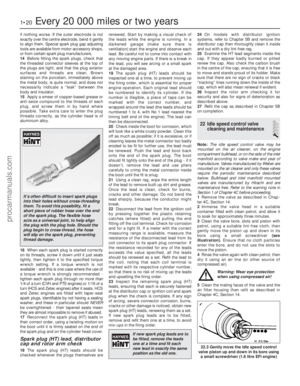 21
21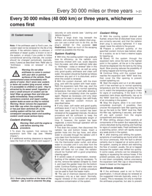 22
22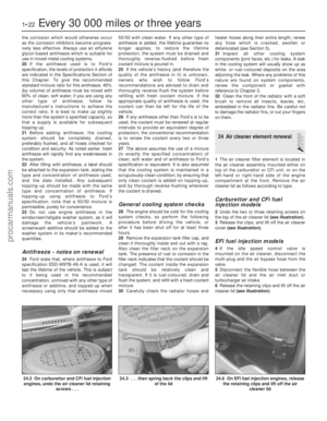 23
23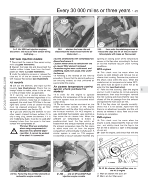 24
24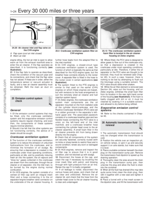 25
25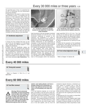 26
26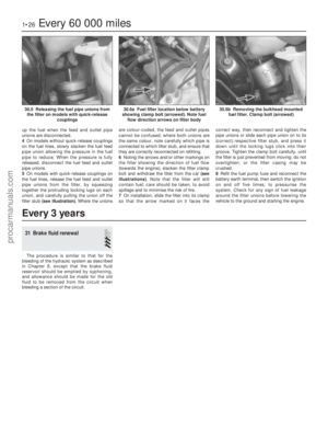 27
27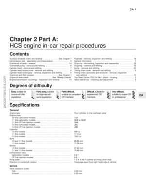 28
28 29
29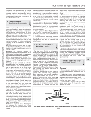 30
30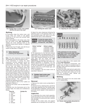 31
31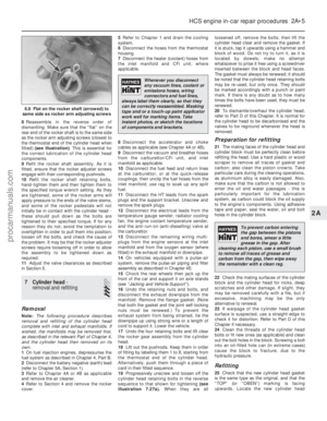 32
32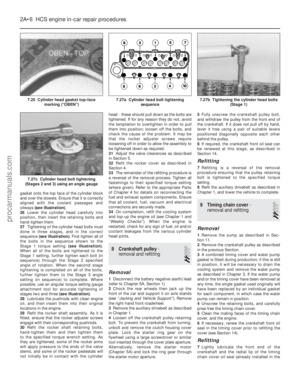 33
33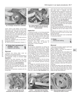 34
34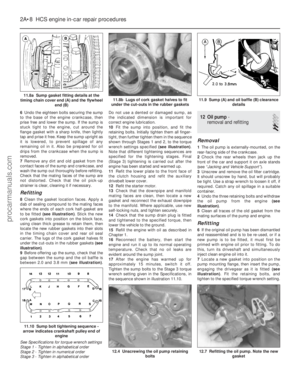 35
35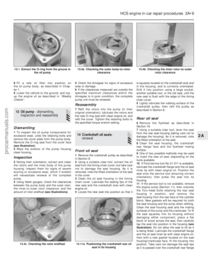 36
36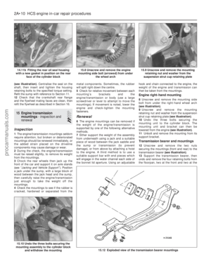 37
37 38
38 39
39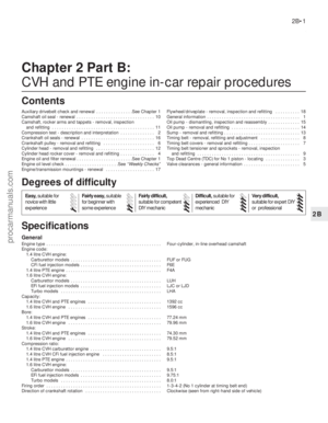 40
40 41
41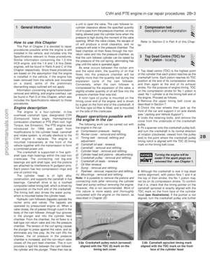 42
42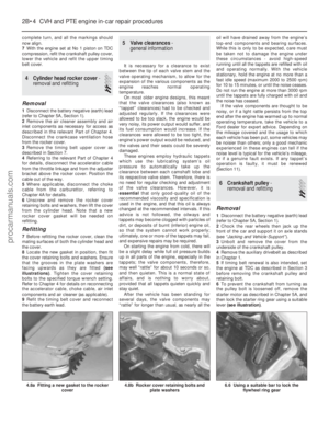 43
43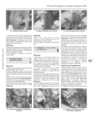 44
44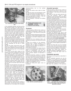 45
45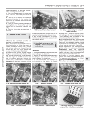 46
46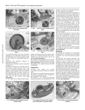 47
47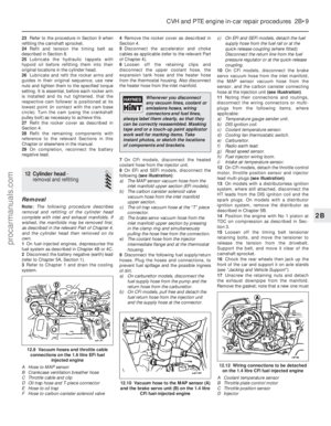 48
48 49
49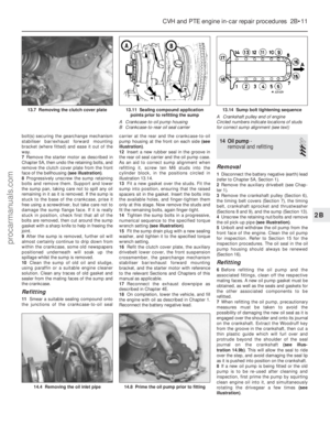 50
50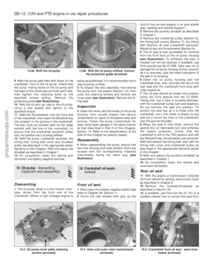 51
51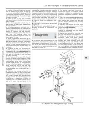 52
52 53
53 54
54 55
55 56
56 57
57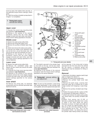 58
58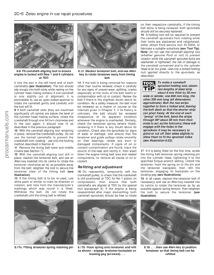 59
59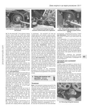 60
60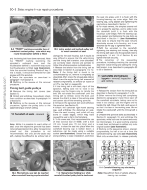 61
61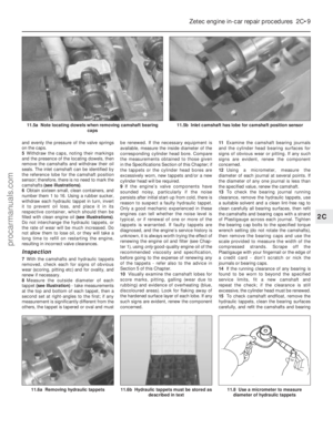 62
62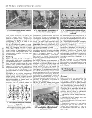 63
63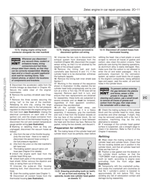 64
64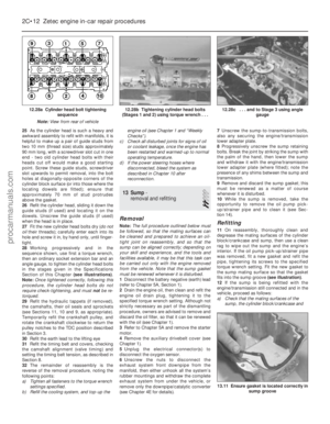 65
65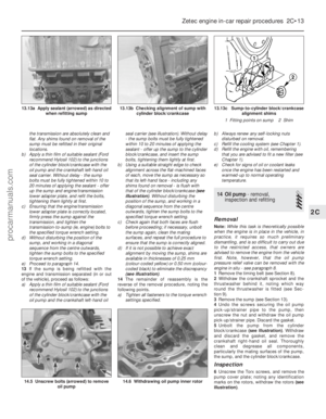 66
66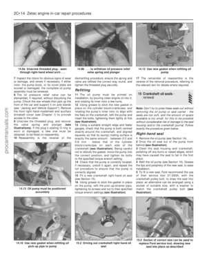 67
67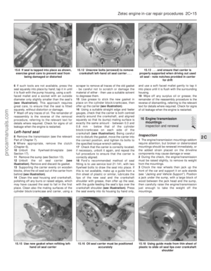 68
68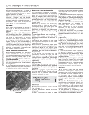 69
69 70
70 71
71 72
72 73
73 74
74 75
75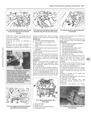 76
76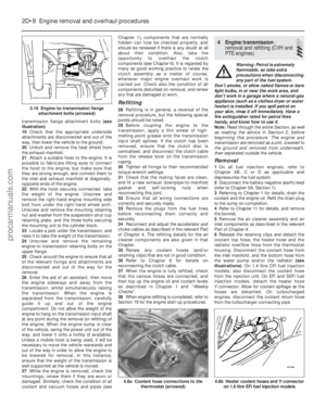 77
77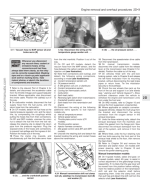 78
78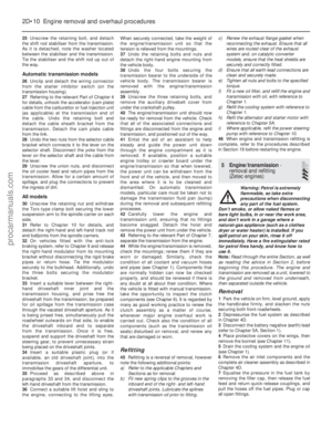 79
79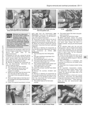 80
80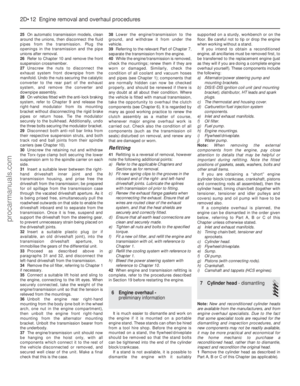 81
81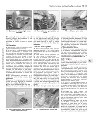 82
82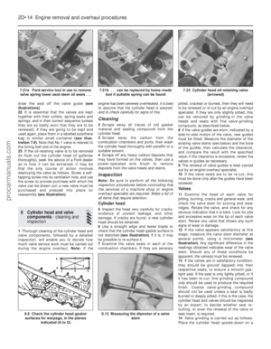 83
83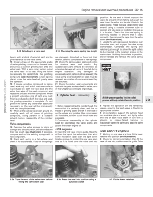 84
84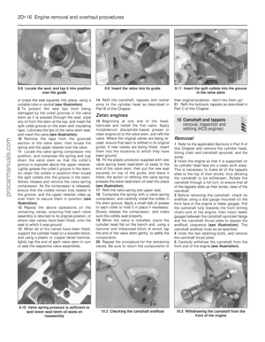 85
85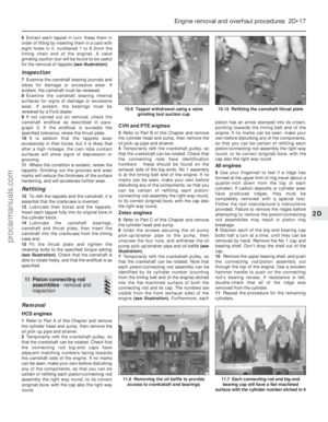 86
86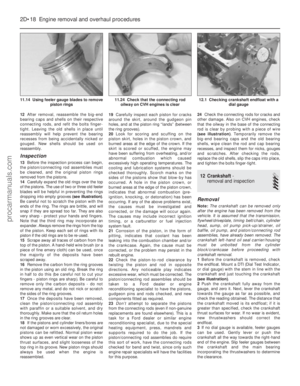 87
87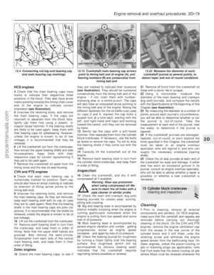 88
88 89
89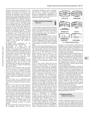 90
90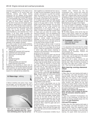 91
91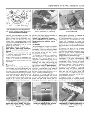 92
92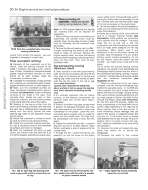 93
93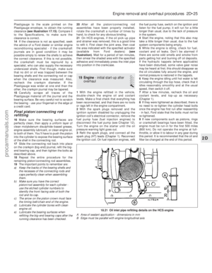 94
94 95
95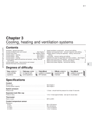 96
96 97
97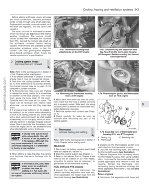 98
98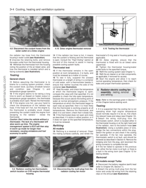 99
99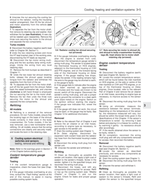 100
100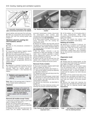 101
101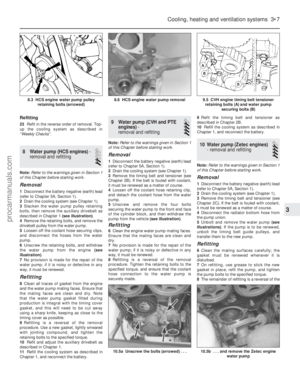 102
102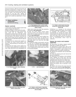 103
103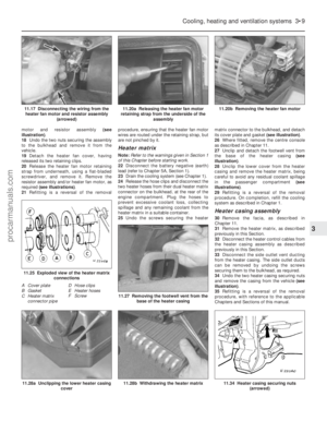 104
104 105
105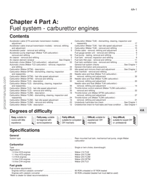 106
106 107
107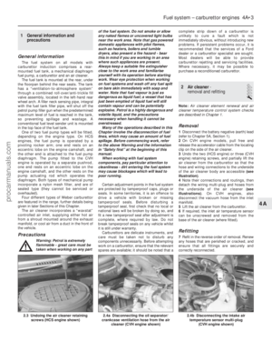 108
108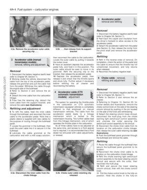 109
109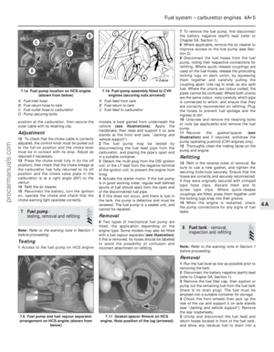 110
110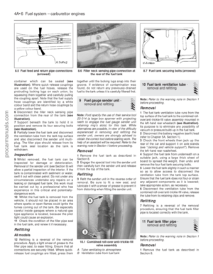 111
111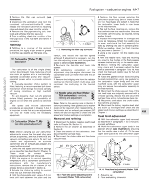 112
112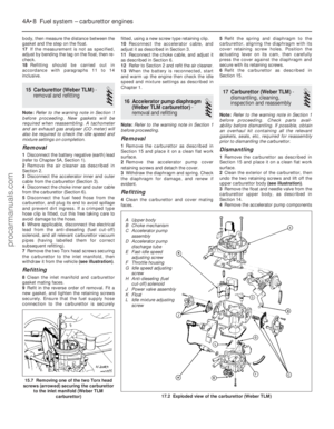 113
113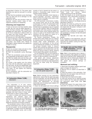 114
114 115
115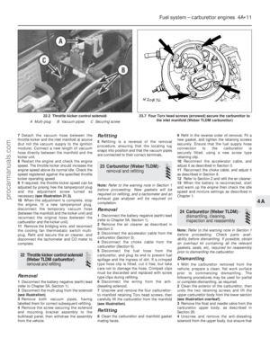 116
116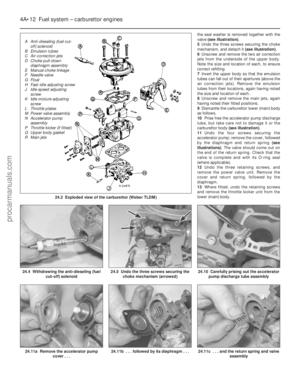 117
117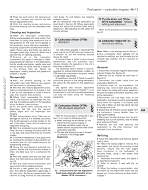 118
118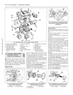 119
119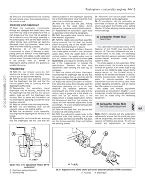 120
120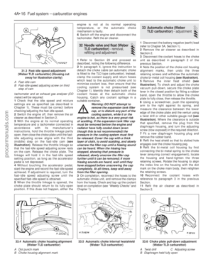 121
121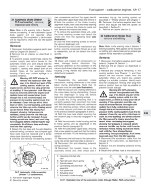 122
122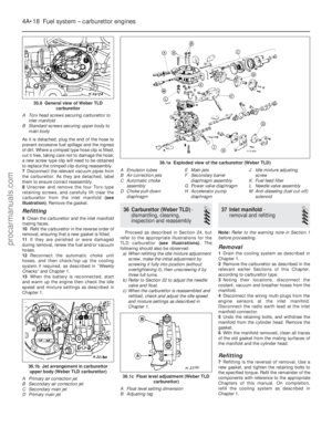 123
123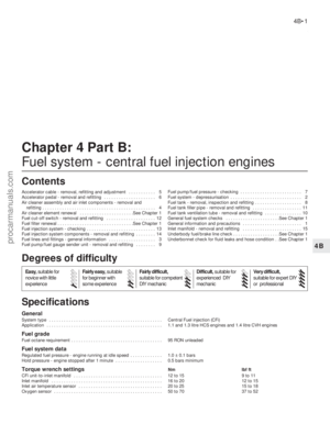 124
124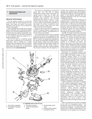 125
125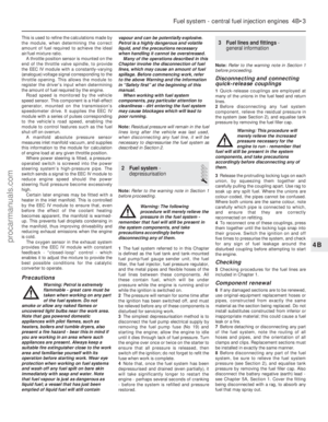 126
126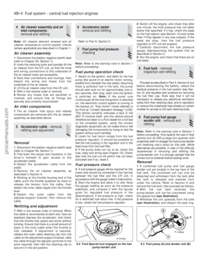 127
127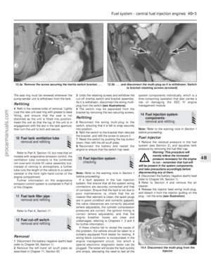 128
128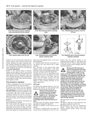 129
129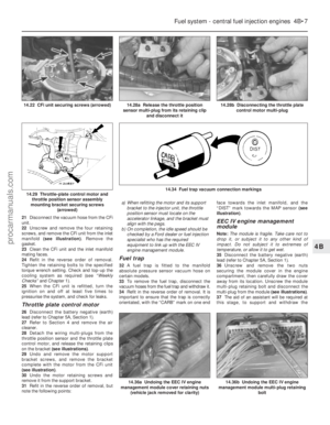 130
130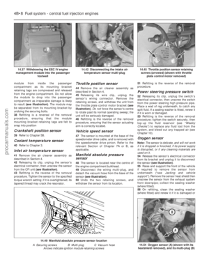 131
131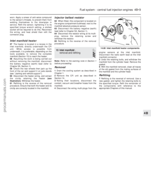 132
132 133
133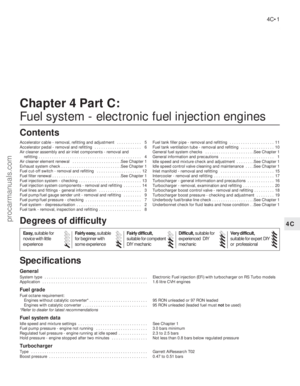 134
134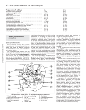 135
135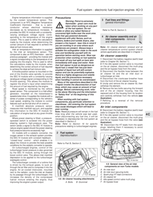 136
136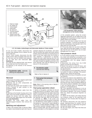 137
137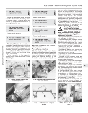 138
138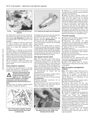 139
139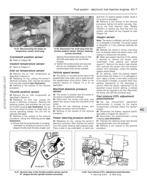 140
140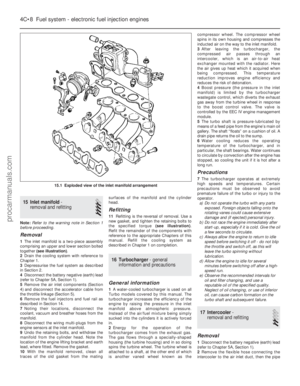 141
141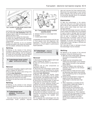 142
142 143
143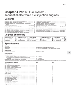 144
144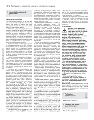 145
145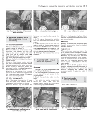 146
146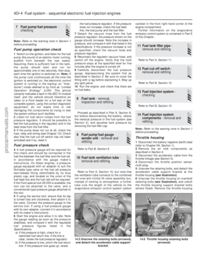 147
147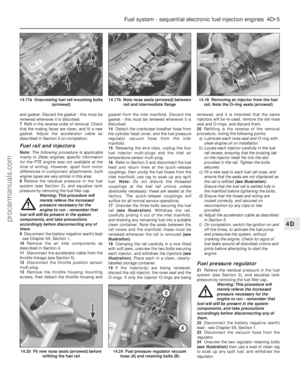 148
148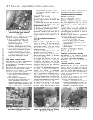 149
149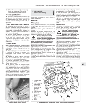 150
150 151
151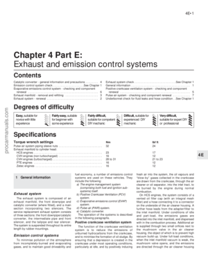 152
152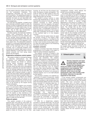 153
153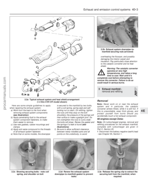 154
154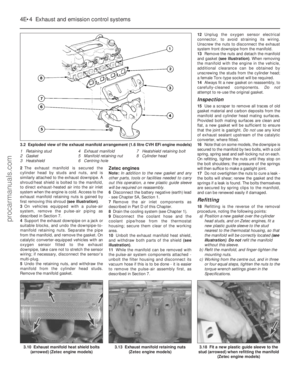 155
155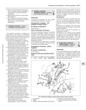 156
156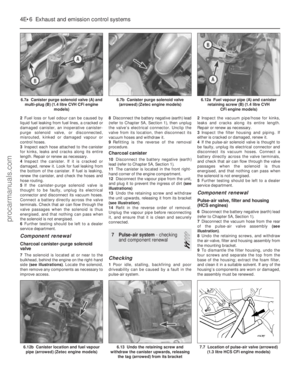 157
157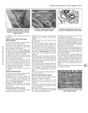 158
158 159
159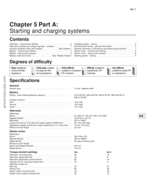 160
160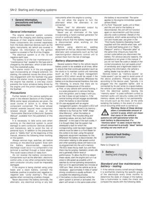 161
161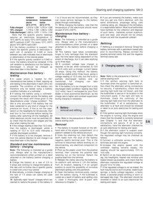 162
162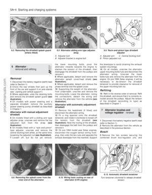 163
163 164
164 165
165 166
166 167
167 168
168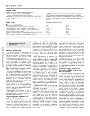 169
169 170
170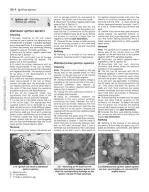 171
171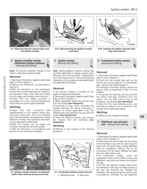 172
172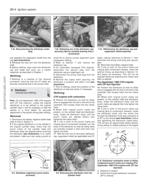 173
173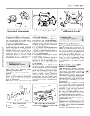 174
174 175
175 176
176 177
177 178
178 179
179 180
180 181
181 182
182 183
183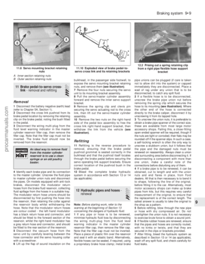 184
184 185
185 186
186 187
187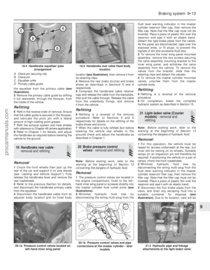 188
188 189
189 190
190 191
191 192
192 193
193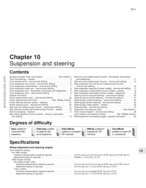 194
194 195
195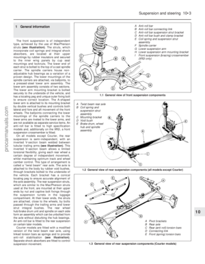 196
196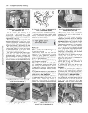 197
197 198
198 199
199 200
200 201
201 202
202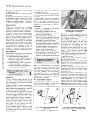 203
203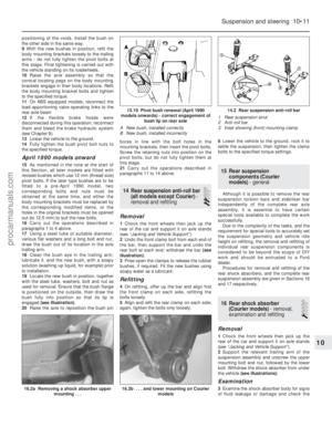 204
204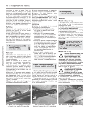 205
205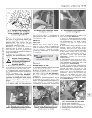 206
206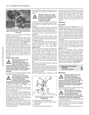 207
207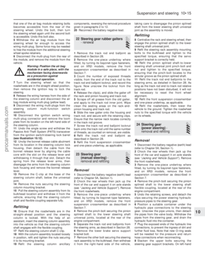 208
208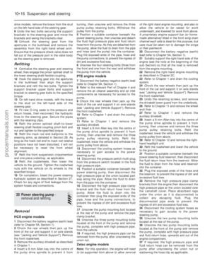 209
209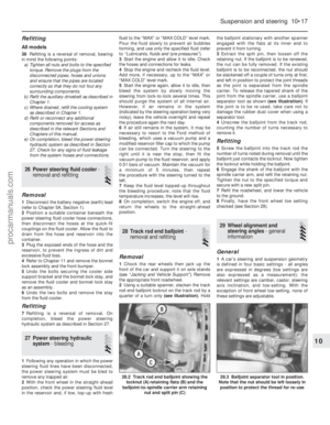 210
210 211
211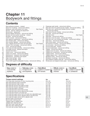 212
212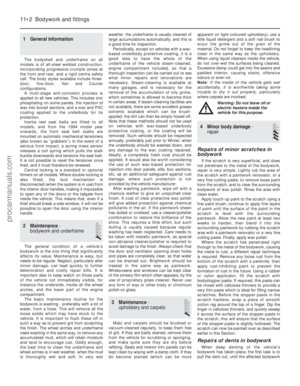 213
213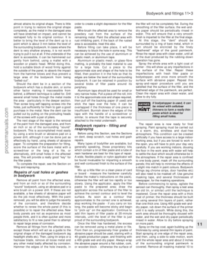 214
214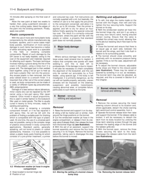 215
215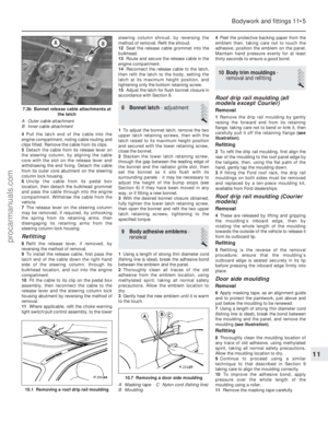 216
216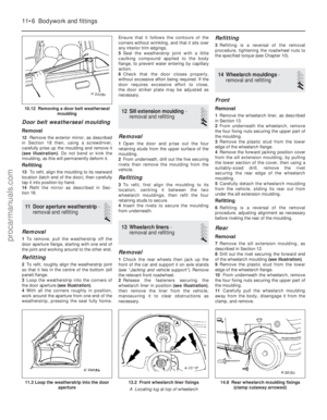 217
217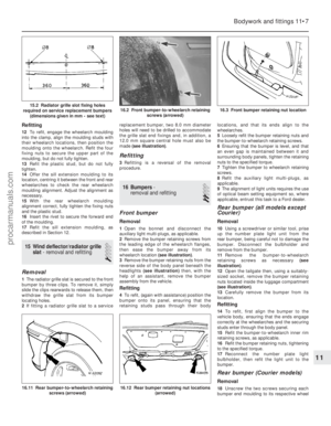 218
218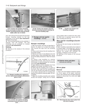 219
219 220
220 221
221 222
222 223
223 224
224 225
225 226
226 227
227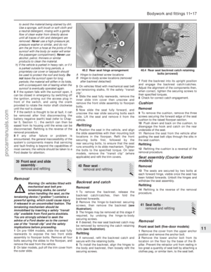 228
228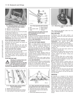 229
229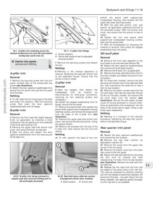 230
230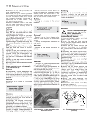 231
231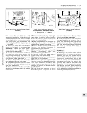 232
232 233
233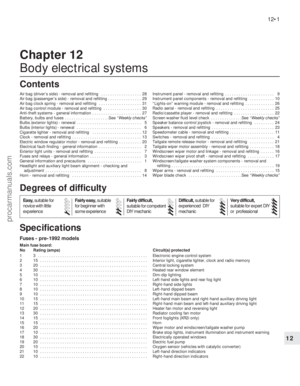 234
234 235
235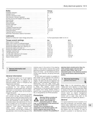 236
236 237
237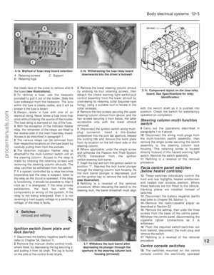 238
238 239
239 240
240 241
241 242
242 243
243 244
244 245
245 246
246 247
247 248
248 249
249 250
250 251
251 252
252 253
253 254
254 255
255 256
256 257
257 258
258 259
259 260
260 261
261 262
262 263
263 264
264 265
265 266
266 267
267 268
268 269
269 270
270 271
271 272
272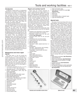 273
273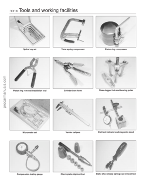 274
274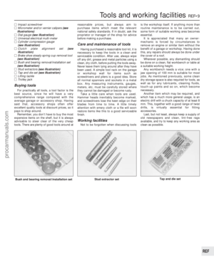 275
275 276
276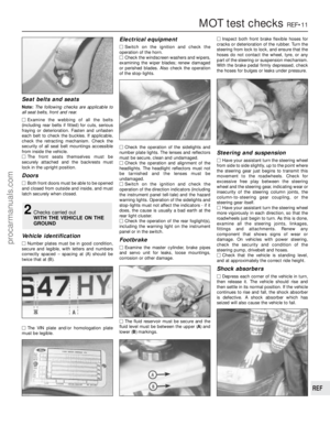 277
277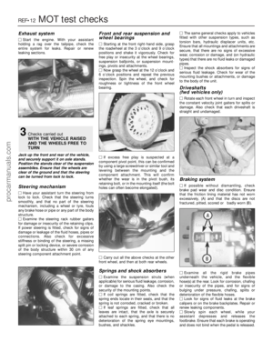 278
278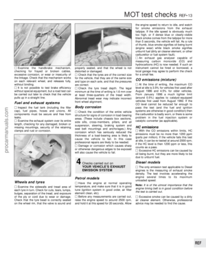 279
279 280
280 281
281 282
282 283
283 284
284 285
285 286
286 287
287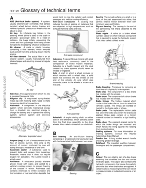 288
288 289
289 290
290 291
291 292
292 293
293 294
294 295
295