Page 57 of 296

clamp brackets and disconnect the pipe joint
union over the top of the cylinder head cover.
Place absorbent rags beneath the union as it
is disconnected to soak up escaping fluid and
plug the open unions to prevent dirt entry and
further fluid loss. Move the pipe(s) clear just
sufficiently to allow removal of the cylinder
head cover.
5Remove the timing belt upper cover (see
Section 7).
6 Disconnect the crankcase breather hose
from the cylinder head cover union (see
illustration) .
7 Unplug the HT leads from the spark plugs
and withdraw them, unclipping the leads from
the cover.
8 Working progressively, unscrew the
cylinder head cover retaining bolts, noting the
spacer sleeve and rubber seal at each, then
withdraw the cover (see illustration).
9 Discard the cover gasket; this mustbe
renewed whenever it is disturbed. Check that
the sealing faces are undamaged, and that the
rubber seal at each retaining bolt is
serviceable; renew any worn or damaged
seals.
Refitting
10 On refitting, clean the cover and cylinder
head gasket faces carefully, then fit a new
gasket to the cover, ensuring that it locates
correctly in the cover grooves (see illustration).
11 Refit the cover to the cylinder head, then
insert the rubber seal and spacer sleeve at
each bolt location (see illustration). Start allbolts finger-tight, ensuring that the gasket
remains seated in its groove.
12
Working in a diagonal sequence from the
centre outwards, and in two stages (see
Specifications), tighten the cover bolts to the
specified torque wrench setting.
13 Refit the HT leads, clipping them into
place so that they are correctly routed; each is
numbered, and can also be identified by the
numbering on its respective coil terminal.
14 Reconnect the crankcase breather hose,
and refit the timing belt upper cover.
Reconnect and adjust the accelerator cable,
then refit the air inlet components (see
Chapter 4B).
15 On models with power steering,
reconnect the high pressure fluid pipe then
bleed the system as described in Chapter 10.
5 Valve clearances -
general information
Refer to Section 5 in Part B of this Chapter.
6 Crankshaft pulley -
removal and refitting
1
Removal
1 Remove the auxiliary drivebelt - either
remove the drivebelt completely, or just secure it clear of the crankshaft pulley,
depending on the work to be carried out (see
Chapter 1).
2
If necessary, rotate the crankshaft until the
timing marks align (see Section 3).
3 The crankshaft must now be locked to
prevent its rotation while the pulley bolt is
unscrewed. To do this, remove the starter
motor (Chapter 5A) and lock the starter ring
gear teeth using a suitable screwdriver.
4 It should now just be possible to reach
between the crankshaft pulley and the body
side member to undo and remove the pulley
bolt and withdraw the pulley. However, if
additional working clearance is needed,
proceed as follows.
5 If not already done, chock the rear wheels
then jack up the front of the car and support it
on axle stands (see “Jacking and Vehicle
Support” ). Remove the front right-hand
roadwheel.
6 Support the weight of the
engine/transmission using a trolley jack, with
a wooden spacer to prevent damage to the
sump.
7 From above, unscrew the three bolts
securing the engine’s front right-hand (Y-
shaped) mounting bracket to the alternator
mounting bracket. Unfasten the engine’s rear
right-hand mounting from the body by
unscrewing first the single nut (and washer)
immediately to the rear of the timing belt
cover, then the bolt in the wheel arch
8 With the engine’s right-hand mountings
unfastened from the body, lower the
engine/transmission on the jack until a socket
spanner can be fitted to the crankshaft pulley
bolt.
9 With the starter ring gear teeth locked,
unscrew the crankshaft pulley bolt and
withdraw the pulley (see illustration).
Refitting
10Refitting is the reverse of the removal
procedure; ensure that the pulley’s keyway is
aligned with the crankshaft’s locating key, and
tighten the pulley bolt to the specified torque
wrench setting. If the engine mountings were
disturbed, use the jack to adjust the height of
the engine/transmission until the bolts (and
nut, with washer) can be refitted and screwed
2C•4 Zetec engine in-car repair procedures
6.9 Unscrew pulley bolt to release
crankshaft pulley4.11 Ensure rubber seal is fitted to eachcover bolt spacer, as shown
4.10 Ensure gasket is located correctly in cover groove4.8 Removing cylinder head cover
1595Ford Fiesta Remake
4.6 Disconnecting crankcase breather
hose from cylinder head cover unionprocarmanuals.com
http://vnx.su
Page 58 of 296

home by hand, then tighten them securely, to
the specified torque wrench settings, where
given.
11Refit the auxiliary drivebelt as described in
Chapter 1 on completion.
7 Timing belt covers -
removal and refitting
4
Upper cover
1 Unscrew the cover’s two mounting bolts
and withdraw it (see illustration) .
2 Refitting is the reverse of the removal
procedure; ensure that the cover edges
engage correctly with each other, and note the
torque wrench setting specified for the bolts.
Middle cover
3 Slacken the water pump pulley bolts.
4 Remove the timing belt upper cover.
5 Remove the auxiliary drivebelt (see Chap-
ter 1).
6 Unbolt and remove the water pump pulley.
7 Unscrew the middle cover fasteners (one
bolt at the front, one at the lower rear, one
stud at the top rear) and withdraw the cover.
8 Refitting is the reverse of the removal
procedure. Ensure that the cover edges
engage correctly with each other, and note
the torque wrench settings specified for the
various fasteners.
Lower cover
9 Slacken the water pump pulley bolts.
10 Remove the crankshaft pulley (see
Section 6) then unbolt and remove the water
pump pulley.
11 Unscrew the three cover securing bolts,
and withdraw it (see illustration) .
12 Refitting is the reverse of the removal
procedure; ensure the cover edges engage
correctly with each other, and note the torque
wrench settings specified for the various
fasteners.
Inner shield
13 Remove the timing belt, its tensioner
components and the camshaft sprockets (see
Sections 8 and 9). 14
The shield is secured to the cylinder head
by two bolts at the top, and by two studs
lower down; unscrew these and withdraw the
shield (see illustration) .
15 Refitting is the reverse of the removal
procedure; note the torque wrench settings
specified for the various fasteners.
8 Timing belt - removal, refitting
and adjustment
4
Note: To carry out this operation, a new timing
belt (where applicable), a new cylinder head
cover gasket, and some special tools (see text) will be required. If the timing belt is being
removed for the first time since the vehicle
left the factory, a tensioner spring and
retaining pin must be obtained for fitting on
reassembly.
Removal
1
Disconnect the battery negative (earth) lead
(refer to Chapter 5A, Section 1).
2 Slacken the water pump pulley bolts.
3 Remove the cylinder head cover (see
Section 4).
4 Remove the spark plugs, covering their
holes with clean rag, to prevent dirt or other
foreign bodies from dropping in (see Chap-
ter 1).
5 Remove the auxiliary drivebelt (see Chap-
ter 1).
6 Position the engine with No 1 piston at TDC
on compression as described in Section 3.
7 Unbolt and remove the water pump pulley
and, where fitted, the auxiliary drivebelt idler
pulley.
8 Obtain Ford service tool 21-162, or
fabricate a substitute alternative from a strip
of metal 5 mm thick (while the strip’s
thickness iscritical, its length and width are
not, but should be approximately 180 to
230 mm by 20 to 30 mm). Check that Nos 1
and 4 cylinders are at TDC - No 1 on the
compression stroke - by resting this tool on
the cylinder head mating surface, and sliding
Zetec engine in-car repair procedures 2C•5
7.11 Removing timing belt lower cover - bolt locations arrowed7.14 Timing belt inner shield fasteners (arrowed)
7.1 Timing belt and cover details2C
1595Ford Fiesta Remake 1 Timing belt upper
cover
2 Inlet camshaft
toothed pulley
3 Exhaust camshaft
toothed pulley
4 Timing belt
5 Timing belt
tensioner
6 Crankshaft toothed pulley
7 Timing belt middle cover
8 Timing belt lower
cover
9 Crankshaft pulley
10 Water pump pulleyprocarmanuals.com
http://vnx.su
Page 59 of 296
 . The tool should
slip snugly into both slots while resting on the
cylinder head mating surface; if one camshaft
is only slig")
it into the slot in the left-hand end of both
camshafts (see illustration) . The tool should
slip snugly into both slots while resting on the
cylinder head mating surface; if one camshaft
is only slightly out of alignment, it is
permissible to use an open-ended spanner to
rotate the camshaft gently and carefully until
the tool will fit.
9 If both camshaft slots (they are machined
significantly off-centre) are below the level of
the cylinder head mating surface, rotate the
crankshaft through one full turn clockwise and
fit the tool again; it should now fit as
described in the previous paragraph.
10 With the camshaft aligning tool remaining
in place, remove the crankshaft pulley. Do not
use the locked camshafts to prevent the
crankshaft from rotating - use only the locking
method described in Section 6.
11 Remove the timing belt lower and middle
covers (see Section 7).
12 With the camshaft-aligning tool still in
place, slacken the tensioner bolt, and use an
Allen key inserted into its centre to rotate the
tensioner clockwise as far as possible away
from the belt; retighten the bolt to secure the
tensioner clear of the timing belt (see
illustration) .
13 If the timing belt is to be re-used, use
white paint or similar to mark its direction of
rotation, and note from the manufacturer’s
markings which way round it is fitted.
Withdraw the belt. Do notrotate the
crankshaft until the timing belt is refitted. 14
If the belt is being removed for reasons
other than routine renewal, check it carefully
for any signs of uneven wear, splitting, cracks
(especially at the roots of the belt teeth) or
contamination with oil or coolant. Renew the
belt if there is the slightest doubt about its
condition. As a safety measure, the belt must
be renewed as a matter of course at the
intervals given in Chapter 1; if its history is
unknown, the belt should be renewed
irrespective of its apparent condition
whenever the engine is overhauled. Similarly,
check the tensioner spring (where fitted),
renewing it if there is any doubt about its
condition. Check also the sprockets for signs
of wear or damage, and ensure that the
tensioner and guide pulleys rotate smoothly
on their bearings; renew any worn or
damaged components. If signs of oil or
coolant contamination are found, trace the
source of the leak and rectify it, then wash
down the engine timing belt area and related
components, to remove all traces of oil or
coolant.
Refitting and adjustment
15 On reassembly, temporarily refit the
crankshaft pulley, to check that the crankshaft
is still positioned at TDC for No 1 piston on
compression, then ensure that both
camshafts are aligned at TDC by the special
tool (paragraph 8). If the engine is being
reassembled after major dismantling, both
camshaft sprockets should be free to rotate on their respective camshafts; if the timing
belt alone is being renewed, both sprockets
should still be securely fastened.
16
A holding tool will be required to prevent
the camshaft sprockets from rotating while
their bolts are slackened and retightened;
either obtain Ford service tool 15-030A, or
fabricate a suitable substitute (see Tool Tip).
Note: Do not use the camshaft-aligning tool
(whether genuine Ford or not) to prevent
rotation while the camshaft sprocket bolts are
slackened or tightened; the risk of damage to
the camshaft concerned and to the cylinder
head is far too great. Use only a forked holding
tool applied directly to the sprockets, as
described.
17 If it is being fitted for the first time, screw
the timing belt tensioner spring retaining pin
into the cylinder head, tightening it to the
specified torque wrench setting. Unbolt the
tensioner, hook the spring on to the pin and
the tensioner backplate, then refit the
tensioner, engaging its backplate on the
locating peg (see illustrations) .
18 In all cases, slacken the tensioner bolt (if
necessary), and use an Allen key inserted into
its centre to rotate the tensioner as far as
possible against spring tension, then retighten
the bolt to secure the tensioner (see
illustration) .
2C•6Zetec engine in-car repair procedures
8.18 . . . then use Allen key to position
tensioner so that timing belt can be
refitted8.17b Hook spring onto tensioner and refitas shown - engage tensioner backplate on
locating peg (arrowed) . . .8.17a Fitting tensioner spring retaining pin
8.12 Slacken tensioner bolt, and use Allenkey to rotate tensioner away from timing belt8.8 Fit camshaft-aligning tool to ensure
engine is locked with Nos 1 and 4 cylinders at TDC
1595Ford Fiesta Remake
To make a camshaft
sprocket holding tool, obtain
two lengths of steel strip
about 6 mm thick by 30 mm
wide or similar, one 600 mm long, the
other 200 mm long (all dimensions
approximate). Bolt the two strips
together to form a forked end, leaving
the bolt slack so that the shorter strip
can pivot freely. At the end of each
“prong” of the fork, bend the strips
through 90º about 50 mm from their
ends to act as the fulcrums; these will
engage with the holes in the
sprockets. It may be necessary to
grind or cut off their sides slightly to
allow them to fit the sprocket holes
(see illustration 8.23).
procarmanuals.com
http://vnx.su
Page 60 of 296

19Fit the timing belt; if the original is being
refitted, ensure that the marks and notes
made on removal are followed, so that the belt
is refitted the same way round, and to run in
the same direction. Starting at the crankshaft
sprocket, work anti-clockwise around the
camshaft sprockets and tensioner, finishing
off at the rear guide pulley. The front run,
between the crankshaft and the exhaust
camshaft sprockets, mustbe kept taut,
without altering the position either of the
crankshaft or of the camshaft(s) - if necessary,
the position of the camshaft sprockets can be
altered by rotating each on its camshaft
(which remains fixed by the aligning tool).
Where the sprocket is still fastened, use the
holding tool described above to prevent the
sprocket from rotating while its retaining bolt
is slackened - the sprocket can then be
rotated on the camshaft until the belt will slip
into place; retighten the sprocket bolt.
20 When the belt is in place, slacken the
tensioner bolt gently until the spring pulls the
tensioner against the belt; the tensioner
should be retained correctly against the timing
belt inner shield and cylinder head, but must
be just free to respond to changes in belt
tension (see illustration) .
21 Tighten both camshaft sprocket bolts (or
check that they are tight, as applicable) and
remove the camshaft-aligning tool.
Temporarily refit the crankshaft pulley, and
rotate the crankshaft through two full turns
clockwise to settle and tension the timing belt,
returning the crankshaft to the TDC position
described previously. Refit the camshaft-
aligning tool; it should slip into place as
described in paragraph 8. If all is well,
proceed to paragraph 24 below.
22 If one camshaft is only just out of line, fit
the forked holding tool to its sprocket, adjust
its position as required, and check that any
slack created has been taken up by the
tensioner; rotate the crankshaft through two
further turns clockwise, and refit the
camshaft-aligning tool to check that it now fits
as it should. If all is well, proceed to
paragraph 24 below.
23 If either camshaft is significantly out of
line, use the holding tool to prevent its
sprocket from rotating while its retaining bolt is slackened - the camshaft can then be
rotated (gently and carefully, using an open-
ended spanner) until the camshaft-aligning
tool will slip into place; take care not to
disturb the relationship of the sprocket to the
timing belt. Without disturbing the sprocket’s
new position on the camshaft, tighten the
sprocket bolt to its specified torque wrench
setting
(see illustration) . Remove the
camshaft-aligning tool, rotate the crankshaft
through two further turns clockwise, and refit
the tool to check that it now fits as it should.
24 When the timing belt has been settled at
its correct tension, and the camshaft-aligning
tool fits correctly when the crankshaft pulley
notches are exactly aligned, tighten the
tensioner bolt to its specified torque wrench
setting (see illustration) . Fitting the forked
holding tool to the spokes of each sprocket in
turn, check that the sprocket bolts are
tightened to their specified torque wrench
setting. Remove the camshaft-aligning tool,
rotate the crankshaft through two further turns
clockwise, and refit the tool to make a final
check that it fits as it should.
25 The remainder of the reassembly
procedure is the reverse of removal, ensuring
that all fasteners are tightened to the specified
torque.
9 Timing belt tensioner and
sprockets - removal,
inspection and refitting
4
Tensioner
Note: If the tensioner is being removed for the
first time since the vehicle left the factory, a
tensioner spring and retaining pin must be
obtained for fitting on reassembly.
1 While it is possible to reach the tensioner
once the timing belt upper and middle covers
only have been removed, the whole
procedure outlined below must be followed,
to ensure that the valve timing is correctly
reset once the belt’s tension has been
disturbed.
2 Release the tension from the timing belt as
described in Section 8, paragraphs 1 to 12.
3 Unscrew the tensioner bolt and withdraw the tensioner, unhooking the spring, if fitted
(see illustration)
. Check the tensioner spring,
and renew it if there is any doubt about its
condition.
4 On reassembly, if it is being fitted for the
first time, screw the timing belt tensioner
spring retaining pin into the cylinder head,
tightening it to the specified torque wrench
setting. Hook the spring onto the pin and the
tensioner backplate, then refit the tensioner,
engaging its backplate on the locating peg.
5 Use an Allen key inserted into its centre to
rotate the tensioner as far as possible against
spring tension, then tighten the bolt to secure
the tensioner.
6 Reassemble, checking the camshaft
alignment (valve timing) and setting the timing
belt tension, as described in paragraphs 20
to 25 of Section 8.
Camshaft and crankshaft
sprockets
7 While it may be possible to remove any of
these sprockets once the relevant belt covers
have been removed, the complete timing belt
removal/refitting procedure (see Section 8)
must be followed, to ensure that the valve
timing is correctly reset once the belt’s
tension has been disturbed.
8 With the timing belt removed, the camshaft
sprockets can be detached once their
retaining bolts have been unscrewed as
described in paragraph 16 of Section 8. The
crankshaft sprocket can be pulled off the end
of the crankshaft, once the crankshaft pulley
Zetec engine in-car repair procedures 2C•7
8.24 When setting is correct, tighten
tensioner bolt to specified torque wrench setting8.23 Using forked holding tool while
camshaft toothed pulley bolt is tightened8.20 Slacken tensioner bolt to give initial belt tension
9.3 Removing timing belt tensioner
2C
1595Ford Fiesta Remakeprocarmanuals.com
http://vnx.su
Page 61 of 296

and the timing belt have been removed. Note
the “FRONT” marking identifying the
sprocket’s outboard face, and the
thrustwasher behind it; note which way round
the thrustwasher is fitted (see illustration).
Note the sprocket-locating Woodruff key; if
this is loose, it should be removed for safe
storage with the sprocket.
9 Check the sprockets as described in
paragraph 14 of Section 8.
10 Refitting is the reverse of the removal
procedure.
Timing belt guide pulleys
11 Remove the timing belt covers (see
Section 7).
12 Unbolt and withdraw the pulley(s); check
their condition as described in paragraph 14
of Section 8.
13 Refitting is the reverse of the removal
procedure; tighten the pulley bolts to the
specified torque wrench setting.
10 Camshaft oil seals - renewal
4
Note:While it is possible to reach either oil
seal, once the respective sprocket has been
removed (see Section 9) to allow the seal to be
prised out, this procedure is not
recommended. Not only are the seals very
soft, making this difficult to do without risk of damage to the seal housing, but it would be
very difficult to ensure that the valve timing
and the timing belt’s tension, once disturbed,
are correctly reset. Owners are advised to
follow the whole procedure outlined below.
1
Release the tension from the timing belt as
described in Section 8, paragraphs 1 to 12.
Note: If the timing belt is found to be
contaminated by oil, remove it completely as
described, then renew the oil seal (see below).
Wash down the engine timing belt area and all
related components, to remove all traces of
oil. Fit a new belt on reassembly.
2 If the timing belt is still clean, slip it off the
sprocket, taking care not to twist it too
sharply; use the fingers only to handle the
belt. Do not rotate the crankshaft until the
timing belt is refitted. Cover the belt, and
secure it so that it is clear of the working area
and cannot slip off the remaining sprocket.
3 Unfasten the sprocket bolt and withdraw
the sprocket (see Section 9).
4 Unbolt the camshaft right-hand bearing
cap, and withdraw the defective oil seal.
Clean the seal housing, and polish off any
burrs or raised edges, which may have
caused the seal to fail in the first place.
5 To fit a new seal, Ford recommend the use
of their service tool 21-009B, with a bolt
(10 mm thread size, 70 mm long) and a
washer, to draw the seal into place when the
camshaft bearing cap is bolted down; a
substitute can be made using a suitable
socket (see illustration) . Grease the seal lips
and periphery to ease installation, and draw the seal into place until it is flush with the
housing/bearing cap outer edge. Refit the
bearing cap, using sealant and tightening the
cap bolts as described in Section 11.
6
For most owners, the simplest answer will
be to grease the seal lips, and to slide it onto
the camshaft (until it is flush with the
housing’s outer edge). Refit the bearing cap,
using sealant and tightening the cap bolts as
described in Section 11 (see illustration).
Take care to ensure that the seal remains
absolutely square in its housing, and is not
distorted as the cap is tightened down.
7 Refit the sprocket to the camshaft,
tightening the retaining bolt loosely, then slip
the timing belt back onto the sprocket (refer to
paragraphs 16 and 19 of Section 8) and
tighten the bolt securely.
8 The remainder of the reassembly
procedure, including checking the camshaft
alignment (valve timing) and setting the timing
belt tension, is as described in paragraphs 20
to 25 of Section 8.
11 Camshafts and hydraulic tappets - removal, inspection
and refitting
4
Removal
1 Release the tension from the timing belt as
described in Section 8, paragraphs 1 to 12.
2 Either remove the timing belt completely
(Section 8, paragraphs 13 and 14) or slip it off
the camshaft sprockets, taking care not to
twist it too sharply; use the fingers only to
handle the belt. Cover the belt, and secure it
so that it is clear of the working area. Do not
rotate the crankshaft until the timing belt is
refitted.
3 Unfasten the sprocket bolts as described in
Section 8, paragraph 16, and withdraw the
sprockets; while both are the same and could
be interchanged, it is good working practice
to mark them so that each is refitted only to its
original location (see illustration) .
4 Working in the sequence shown, slacken
progressively, by half a turn at a time, the
camshaft bearing cap bolts (see illustration).
Work only as described, to release gradually
2C•8 Zetec engine in-car repair procedures
11.4 Camshaft bearing cap slackening
sequence
Note: Viewed from front of vehicle, showing
bearing cap numbers
11.3 Using forked holding tool while
camshaft toothed pulley bolt is slackened10.6 Alternatively, seal can be inserted
when camshaft bearing cap is unbolted
10.5 Using socket and toothed pulley bolt to install camshaft oil seal9.8 “FRONT” marking on outside face of
crankshaft toothed pulley - note which way round thrustwasher behind is fitted
1595Ford Fiesta Remakeprocarmanuals.com
http://vnx.su
Page 62 of 296

and evenly the pressure of the valve springs
on the caps.
5Withdraw the caps, noting their markings
and the presence of the locating dowels, then
remove the camshafts and withdraw their oil
seals. The inlet camshaft can be identified by
the reference lobe for the camshaft position
sensor; therefore, there is no need to mark the
camshafts (see illustrations) .
6 Obtain sixteen small, clean containers, and
number them 1 to 16. Using a rubber sucker,
withdraw each hydraulic tappet in turn, invert
it to prevent oil loss, and place it in its
respective container, which should then be
filled with clean engine oil (see illustrations).
Do not interchange the hydraulic tappets, or
the rate of wear will be much increased. Do
not allow them to lose oil, or they will take a
long time to refill on restarting the engine,
resulting in incorrect valve clearances.
Inspection
7 With the camshafts and hydraulic tappets
removed, check each for signs of obvious
wear (scoring, pitting etc) and for ovality, and
renew if necessary.
8 Measure the outside diameter of each
tappet (see illustration) - take measurements
at the top and bottom of each tappet, then a
second set at right-angles to the first; if any
measurement is significantly different from the
others, the tappet is tapered or oval and must be renewed. If the necessary equipment is
available, measure the inside diameter of the
corresponding cylinder head bore. Compare
the measurements obtained to those given
in the Specifications Section of this Chapter; if
the tappets or the cylinder head bores are
excessively worn, new tappets and/or a new
cylinder head will be required.
9
If the engine’s valve components have
sounded noisy, particularly if the noise
persists after initial start-up from cold, there is
reason to suspect a faulty hydraulic tappet.
Only a good mechanic experienced in these
engines can tell whether the noise level is
typical, or if renewal of one or more of the
tappets is warranted. If faulty tappets are
diagnosed, and the engine’s service history is
unknown, it is always worth trying the effect of
renewing the engine oil and filter (see Chap-
ter 1), using onlygood-quality engine oil of the
recommended viscosity and specification,
before going to the expense of renewing any
of the tappets - refer also to the advice in
Section 5 of this Chapter.
10 Visually examine the camshaft lobes for
score marks, pitting, galling (wear due to
rubbing) and evidence of overheating (blue,
discoloured areas). Look for flaking away of
the hardened surface layer of each lobe. If any
such signs are evident, renew the component
concerned. 11
Examine the camshaft bearing journals
and the cylinder head bearing surfaces for
signs of obvious wear or pitting. If any such
signs are evident, renew the component
concerned.
12 Using a micrometer, measure the
diameter of each journal at several points. If
the diameter of any one journal is less than
the specified value, renew the camshaft.
13 To check the bearing journal running
clearance, remove the hydraulic tappets, use
a suitable solvent and a clean lint-free rag to
clean carefully all bearing surfaces, then refit
the camshafts and bearing caps with a strand
of Plastigauge across each journal. Tighten
the bearing cap bolts to the specified torque
wrench setting (do not rotate the camshafts),
then remove the bearing caps and use the
scale provided to measure the width of the
compressed strands. Scrape off the
Plastigauge with your fingernail or the edge of
a credit card - don’t scratch or nick the
journals or bearing caps.
14 If the running clearance of any bearing is
found to be worn to beyond the specified
service limits, fit a new camshaft and
repeat the check; if the clearance is still
excessive, the cylinder head must be renewed.
15 To check camshaft endfloat, remove the
hydraulic tappets, clean the bearing surfaces
carefully, and refit the camshafts and bearing
Zetec engine in-car repair procedures 2C•9
11.6a Removing hydraulic tappets
11.5b Inlet camshaft has lobe for camshaft position sensor11.5a Note locating dowels when removing camshaft bearing caps
11.8 Use a micrometer to measurediameter of hydraulic tappets11.6b Hydraulic tappets must be stored as described in text
2C
1595Ford Fiesta Remakeprocarmanuals.com
http://vnx.su
Page 63 of 296
 mounted on the
cylinder head so that its tip bear")
caps. Tighten the bearing cap bolts to the
specified torque wrench setting, then
measure the endfloat using a DTI (Dial Test
Indicator, or dial gauge) mounted on the
cylinder head so that its tip bears on the
camshaft right-hand end.
16Tap the camshaft fully towards the gauge,
zero the gauge, then tap the camshaft fully
away from the gauge, and note the gauge
reading. If the endfloat measured is found to
be at or beyond the specified service limit, fit
a new camshaft and repeat the check; if the
clearance is still excessive, the cylinder head
must be renewed.
Refitting
17 On reassembly, liberally oil the cylinder
head hydraulic tappet bores and the tappets
(see illustration) . Note that if new tappets are
being fitted, they must be charged with clean
engine oil before installation. Carefully refit the
tappets to the cylinder head, ensuring that
each tappet is refitted to its original bore, and
is the correct way up. Some care will be
required to enter the tappets squarely into
their bores.
18 Liberally oil the camshaft bearings and
lobes. Ensuring that each camshaft is in its
original location, refit the camshafts, locating
each so that the slot in its left-hand end is
approximately parallel to, and just above, the
cylinder head mating surface.
19 Ensure that the locating dowels are pressed firmly into their recesses, and check
that all mating surfaces are completely clean,
unmarked and free from oil. Apply a thin film
of suitable sealant (Ford recommend
Loctite 518) to the mating surfaces of each
camshaft’s right-hand bearing cap
(see
illustration) . Referring to paragraph 6 of
Section 10, some owners may wish to fit the
new camshaft oil seals at this stage.
20 All camshaft bearing caps have a single-
digit identifying number etched on them (see
illustration) . The exhaust camshaft’s bearing
caps are numbered in sequence 0 to 4, the
inlet’s 5 to 9; see illustration 11.21a for details.
Each cap is to be fitted so that its numbered
side faces outwards, to the front (exhaust) or
to the rear (inlet).
21 Ensuring that each cap is kept square to
the cylinder head as it is tightened down, and
working in the sequence shown, tighten the
camshaft bearing cap bolts slowly and by one
turn at a time, until each cap touches the
cylinder head (see illustration) . Next, go
round again in the same sequence, tightening
the bolts to the first stage torque wrench
setting specified, then once more, tightening
them to the second stage setting. Work only
as described, to impose gradually and evenly
the pressure of the valve springs on the caps.
Fit the camshaft-aligning tool; it should slip
into place as described in paragraph 8 of
Section 8 (see illustration) .
22 Wipe off all surplus sealant, so that none
is left to find its way into any oilways. Follow the sealant manufacturer’s instructions as to
the time needed for curing; usually, at least an
hour must be allowed between application of
the sealant and starting the engine.
23
If using Ford’s recommended procedure,
fit new oil seals to the camshafts as described
in paragraph 5 of Section 10.
24 Using the marks and notes made on
dismantling to ensure that each is refitted to
its original camshaft, refit the sprockets to the
camshafts, tightening the retaining bolts
loosely. Slip the timing belt back onto the
sprockets (refer to paragraph 19 of Section 8)
and tighten the bolts securely - use the forked
holding tool described in paragraph 16 of
Section 8.
25 The remainder of the reassembly
procedure, including checking the camshaft
alignment (valve timing) and setting the timing
belt tension, is as described in paragraphs 15
to 25 of Section 8.
12 Cylinder head -
removal and refitting
4
Removal
Note: The following text assumes that the
cylinder head will be removed with both inlet
and exhaust manifolds attached. This
simplifies the procedure, but makes it a bulky
and heavy assembly to handle - an engine
hoist will be required, to prevent the risk of
injury, and to prevent damage to any delicate
components as the assembly is removed and
refitted. If it is wished first to remove the
manifolds, refer to Chapter 4D, then amend
the following procedure accordingly.
1 Depressurise the fuel system (see Chap-
ter 4D).
2 Disconnect the battery negative (earth) lead
(refer to Chapter 5A, Section 1).
3 Refer to Chapter 4D and remove the air
inlet components.
4 Equalise the pressure in the fuel tank by
removing the filler cap, then undo the fuel
feed and return lines connecting the engine to
the chassis (see Chapter 4D). Plug or cap all
open fittings.
2C•10 Zetec engine in-car repair procedures
11.21b Fit camshaft-aligning tool to set TDC position while camshaft toothed
pulleys are refitted
11.21a Camshaft bearing cap tightening sequence
Note: View from front of vehicle - locate
bearing caps according to etched numbers, aligned as described in text
11.20 Etched marks on camshaft bearing
caps must be arranged as shown, and face outwards11.19 Apply sealant to mating surface ofcamshaft right-hand bearing caps11.17 Oil liberally when refitting hydraulic tappets
1595Ford Fiesta Remakeprocarmanuals.com
http://vnx.su
Page 64 of 296
.
7 Remove")
5Disconnect the accelerator cable from the
throttle linkage as described in Chapter 4D.
Secure the cable clear of the engine/
transmission.
6 Remove the auxiliary drivebelt (see Chap-
ter 1).
7 Remove the three screws securing the
wiring “rail” to the rear of the manifold.
Releasing its wire clip, unplug the large
electrical connector (next to the fuel pressure
regulator) to disconnect the engine wiring from
the main loom (see illustration) . Unplug the
electrical connectors on each side of the
ignition coil, and the single connector from
beneath the front of the thermostat housing, to
disconnect the coil and coolant temperature
gauge sender wiring (see illustration).
8 Marking or labelling them as they are
unplugged, disconnect the vacuum hoses as
follows:
a) One from the rear of the throttle housing
(only the one hose - there is no need to
disconnect the second hose running to
the fuel pressure regulator).
b) One from the union on the inlet manifold’s
left-hand end.
c) The braking system vacuum servo unit hose (see Chapter 9 for details).
9 Unbolt the engine earth lead from the
cylinder head lifting eye.
10 Unbolt both parts of the exhaust manifold
heat shield. Either remove the dipstick and
tube, or swing them out of the way.
11 Unscrew the pulse-air filter housing
retaining bolt, then disconnect its vacuum
hose.
12 Drain the cooling system (see Chapter 1).
13 Disconnect all coolant hoses from the
thermostat housing (see illustration).14
Unscrew the two nuts to disconnect the
exhaust system front downpipe from the
manifold (Chapter 4B); disconnect the oxygen
sensor wiring, so that it is not strained by the
weight of the exhaust system.
15 Remove the timing belt and both
camshafts (see Sections 8 and 11); if the
cylinder head is to be dismantled, withdraw
the hydraulic tappets.
16 Remove the timing belt inner shield (see
Section 7.
17 Working in the reverseof the sequence
shown in illustration 12.28a, slacken the ten
cylinder head bolts progressively and by one
turn at a time; a Torx key (TX 55 size) will be
required. Remove each bolt in turn, and
ensure that new replacements are obtained
for reassembly; these bolts are subjected to
severe stresses and so mustbe renewed,
regardless of their apparent condition,
whenever they are disturbed.
18 Lift the cylinder head away; use
assistance if possible, as it is a heavy
assembly. If necessary, grip the manifolds
and rock it free from the location dowels on
the top face of the cylinder block. Do not
attempt to tap it sideways or lever between
the head and the block top face. Remove the
gasket, noting the two dowels, and discard it.
Preparation for refitting
19 The mating faces of the cylinder head and
cylinder block must be perfectly clean before refitting the head. Use a hard plastic or wood
scraper to remove all traces of gasket and
carbon; also clean the piston crowns. Take
particular care during the cleaning operations,
as aluminium alloy is easily damaged. Also,
make sure that the carbon is not allowed to
enter the oil and water passages - this is
particularly important for the lubrication
system, as carbon could block the oil supply
to the engine’s components. Using adhesive
tape and paper, seal the water, oil and bolt
holes in the cylinder block.
20
Check the mating surfaces of the cylinder
block and the cylinder head for nicks, deep
scratches and other damage. If slight, they
may be removed carefully with a file, but if
excessive, machining may be the only
alternative to renewal.
21 If warpage of the cylinder head gasket
surface is suspected, use a straight-edge to
check it for distortion. Refer to Part D of this
Chapter if necessary.
Refitting
22 Wipe clean the mating surfaces of the
cylinder head and cylinder block. Check that
the two locating dowels are in position in the
cylinder block, and that all cylinder head bolt
holes are free from oil.
23 Position a new gasket over the dowels on
the cylinder block surface, so that the
“TOP/OBEN” mark is uppermost, and with the
tooth (or teeth, according to engine size)
protruding from the front edge (see
illustration) .
24 Temporarily refit the crankshaft pulley,
and rotate the crankshaft anti-clockwise so
that No 1 cylinder’s piston is lowered to
approximately 20 mm before TDC, thus
avoiding any risk of valve/piston contact and
damage during reassembly.
Zetec engine in-car repair procedures 2C•11
12.13 Disconnect all coolant hoses from thermostat housing12.7b Unplug connectors (arrowed) todisconnect ignition coil wiring12.7a Unplug engine wiring loom
connector alongside the inlet manifold
12.23 Ensuring protruding tooth (or teeth) “A” are at front and marking “B” is
upwards, locate new cylinder head gasket on dowels “C”
2C
1595Ford Fiesta Remake
Whenever you disconnect
any vacuum lines, coolant or
emissions hoses, wiring
connectors and fuel lines,
always label them clearly, so that they
can be correctly reassembled. Masking
tape and/or a touch-up paint applicator
work well for marking items. Take
instant photos, or sketch the locations
of components and brackets.
To prevent carbon entering
the gap between the pistons
and bores, smear a little
grease in the gap. After
cleaning each piston, use a small brush
to remove all traces of grease and
carbon from the gap, then wipe away
the remainder with a clean rag.
procarmanuals.com
http://vnx.su
 1
1 2
2 3
3 4
4 5
5 6
6 7
7 8
8 9
9 10
10 11
11 12
12 13
13 14
14 15
15 16
16 17
17 18
18 19
19 20
20 21
21 22
22 23
23 24
24 25
25 26
26 27
27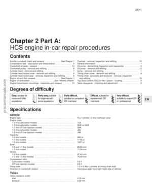 28
28 29
29 30
30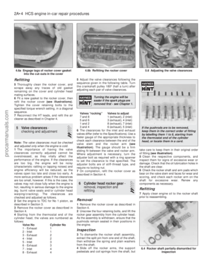 31
31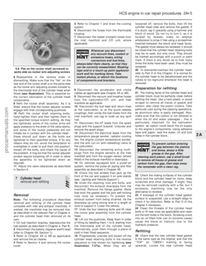 32
32 33
33 34
34 35
35 36
36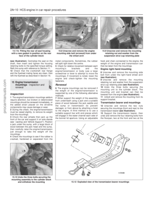 37
37 38
38 39
39 40
40 41
41 42
42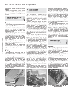 43
43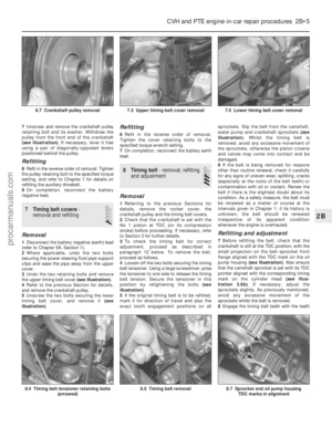 44
44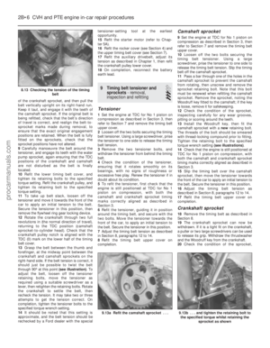 45
45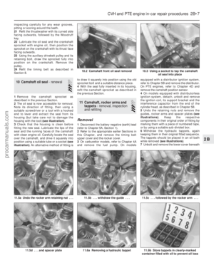 46
46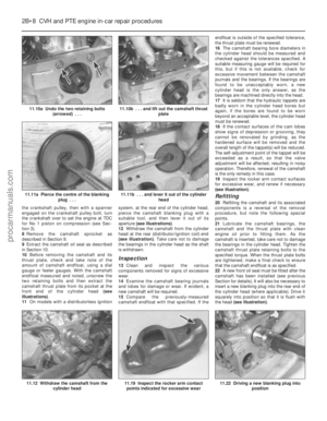 47
47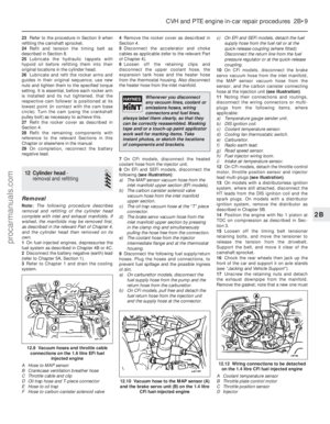 48
48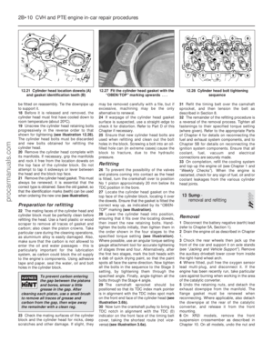 49
49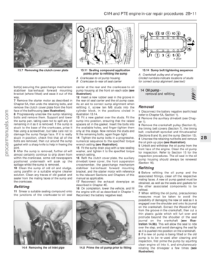 50
50 51
51 52
52 53
53 54
54 55
55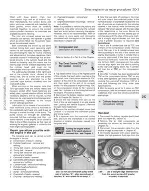 56
56 57
57 58
58 59
59 60
60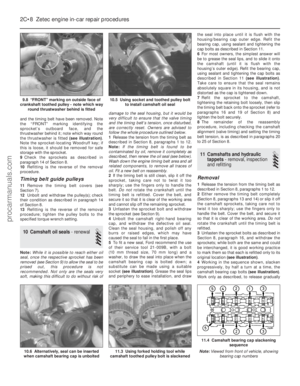 61
61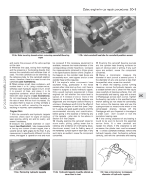 62
62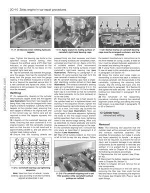 63
63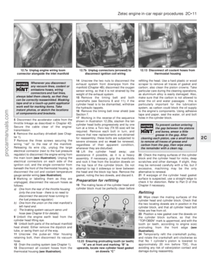 64
64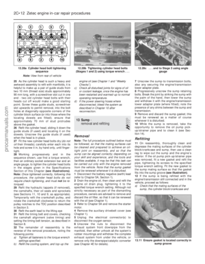 65
65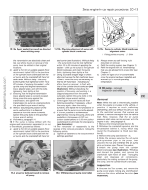 66
66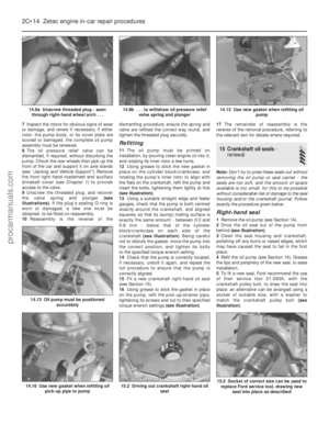 67
67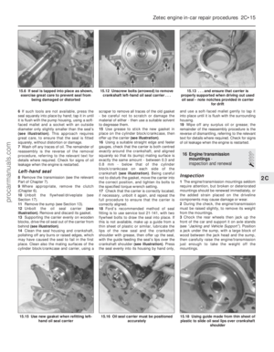 68
68 69
69 70
70 71
71 72
72 73
73 74
74 75
75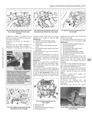 76
76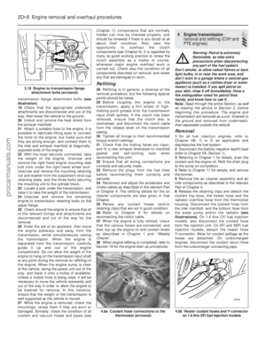 77
77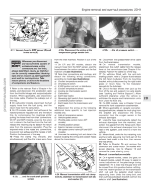 78
78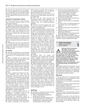 79
79 80
80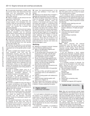 81
81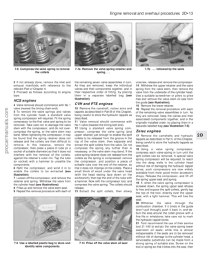 82
82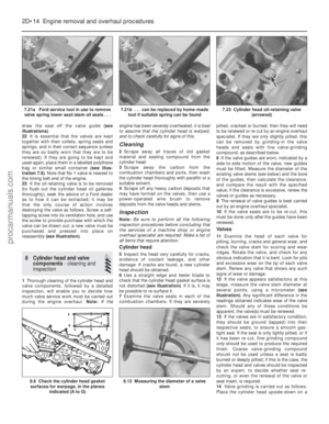 83
83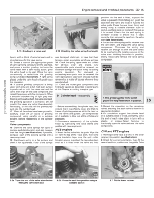 84
84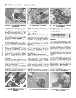 85
85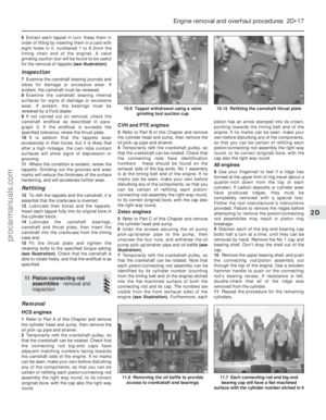 86
86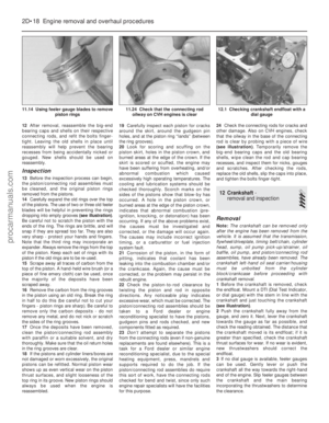 87
87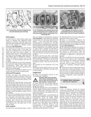 88
88 89
89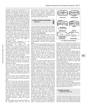 90
90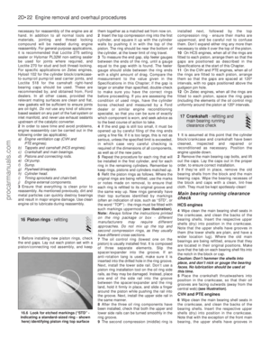 91
91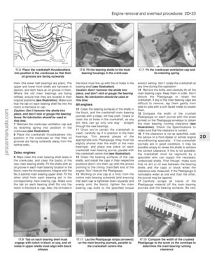 92
92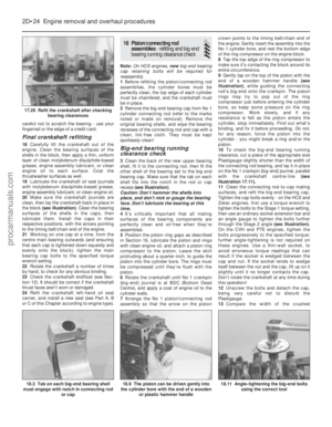 93
93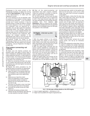 94
94 95
95 96
96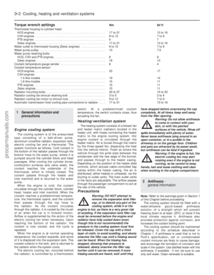 97
97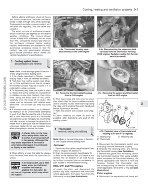 98
98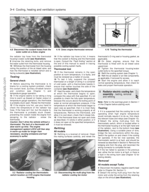 99
99 100
100 101
101 102
102 103
103 104
104 105
105 106
106 107
107 108
108 109
109 110
110 111
111 112
112 113
113 114
114 115
115 116
116 117
117 118
118 119
119 120
120 121
121 122
122 123
123 124
124 125
125 126
126 127
127 128
128 129
129 130
130 131
131 132
132 133
133 134
134 135
135 136
136 137
137 138
138 139
139 140
140 141
141 142
142 143
143 144
144 145
145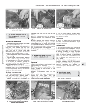 146
146 147
147 148
148 149
149 150
150 151
151 152
152 153
153 154
154 155
155 156
156 157
157 158
158 159
159 160
160 161
161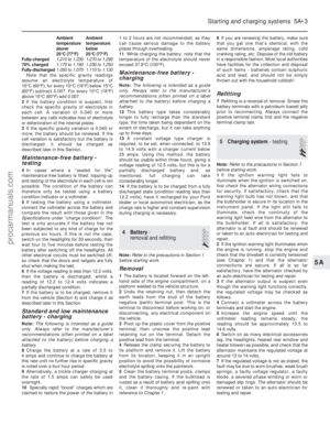 162
162 163
163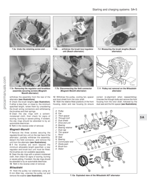 164
164 165
165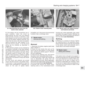 166
166 167
167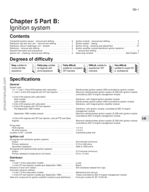 168
168 169
169 170
170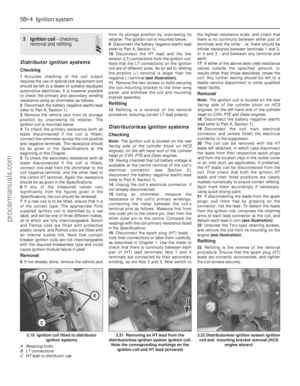 171
171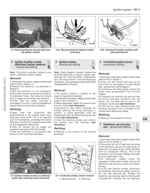 172
172 173
173 174
174 175
175 176
176 177
177 178
178 179
179 180
180 181
181 182
182 183
183 184
184 185
185 186
186 187
187 188
188 189
189 190
190 191
191 192
192 193
193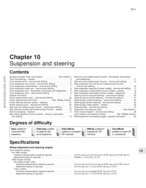 194
194 195
195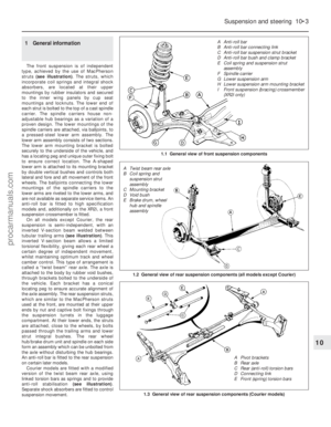 196
196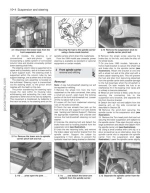 197
197 198
198 199
199 200
200 201
201 202
202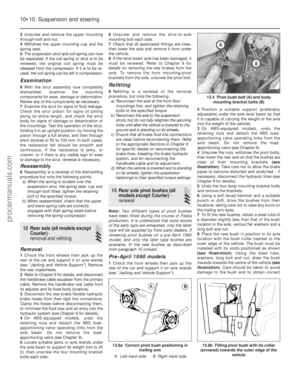 203
203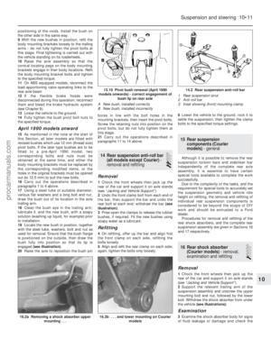 204
204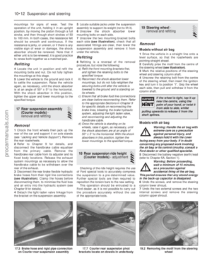 205
205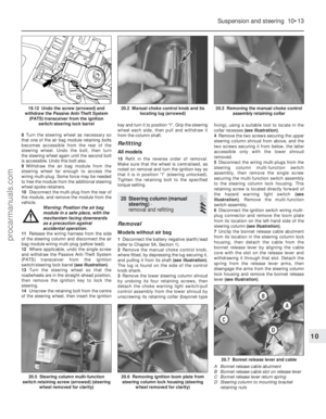 206
206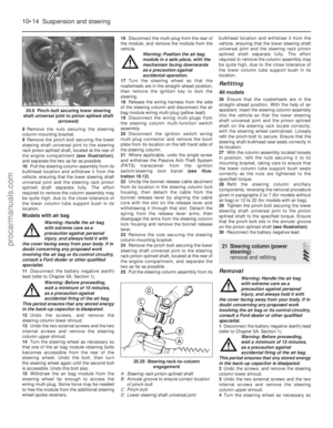 207
207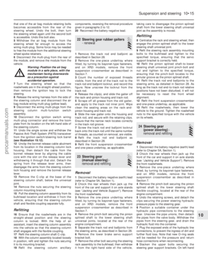 208
208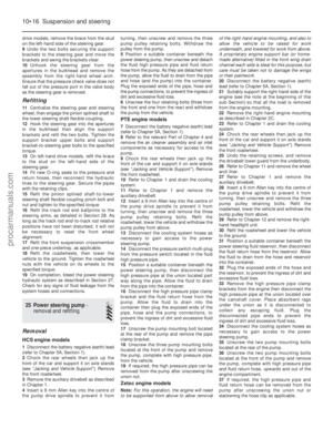 209
209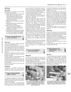 210
210 211
211 212
212 213
213 214
214 215
215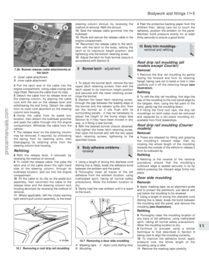 216
216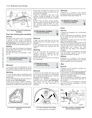 217
217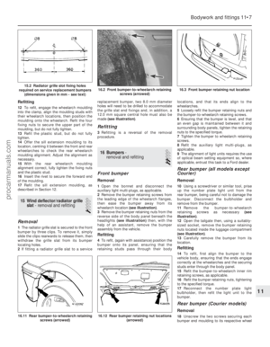 218
218 219
219 220
220 221
221 222
222 223
223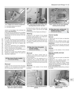 224
224 225
225 226
226 227
227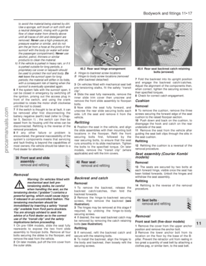 228
228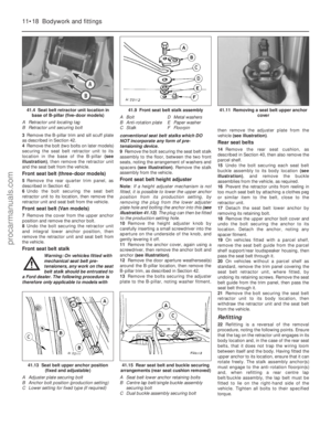 229
229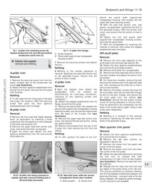 230
230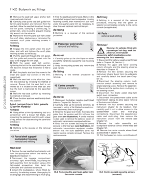 231
231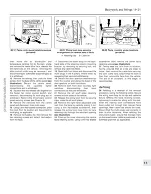 232
232 233
233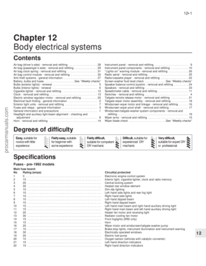 234
234 235
235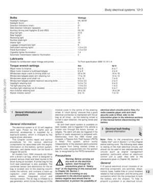 236
236 237
237 238
238 239
239 240
240 241
241 242
242 243
243 244
244 245
245 246
246 247
247 248
248 249
249 250
250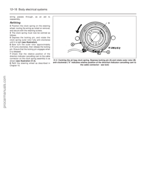 251
251 252
252 253
253 254
254 255
255 256
256 257
257 258
258 259
259 260
260 261
261 262
262 263
263 264
264 265
265 266
266 267
267 268
268 269
269 270
270 271
271 272
272 273
273 274
274 275
275 276
276 277
277 278
278 279
279 280
280 281
281 282
282 283
283 284
284 285
285 286
286 287
287 288
288 289
289 290
290 291
291 292
292 293
293 294
294 295
295