Page 49 of 296
.
19 Unscrew the cylinde")
be fitted on reassembly. Tie the downpipe up
to support it.
18Before it is released and removed, the
cylinder head must first have cooled down to
room temperature (about 20ºC).
19 Unscrew the cylinder head retaining bolts
progressively in the reverse order to that
shown for tightening (see illustration 12.28).
The cylinder head bolts must be discarded
and new bolts obtained for refitting the
cylinder head.
20 Remove the cylinder head complete with
its manifolds. If necessary, grip the manifolds
and rock it free from the location dowels on
the top face of the cylinder block. Do not
attempt to tap it sideways or lever between
the head and the block top face.
21 Remove the cylinder head gasket. This must
always be renewed; it is essential that the
correct type is obtained. Save the old gasket, so
that the identification marks (teeth) can be used
when ordering the new one (see illustration).
Preparation for refitting
22The mating faces of the cylinder head and
cylinder block must be perfectly clean before
refitting the head. Use a hard plastic or wood
scraper to remove all traces of gasket and
carbon; also clean the piston crowns. Take
particular care during the cleaning operations,
as aluminium alloy is easily damaged. Also,
make sure that the carbon is not allowed to
enter the oil and water passages - this is
particularly important for the lubrication
system, as carbon could block the oil supply
to the engine’s components. Using adhesive
tape and paper, seal the water, oil and bolt
holes in the cylinder block.
23 Check the mating surfaces of the cylinder
block and the cylinder head for nicks, deep
scratches and other damage. If slight, they may be removed carefully with a file, but if
excessive, machining may be the only
alternative to renewal.
24
If warpage of the cylinder head gasket
surface is suspected, use a straight-edge to
check it for distortion. Refer to Part D of this
Chapter if necessary.
25 Ensure that new cylinder head bolts are
used when refitting and clean out the bolt
holes in the block. Screwing a bolt into an oil-
filled hole can (in extreme cases) cause the
block to fracture, due to the hydraulic
pressure.
Refitting
26 To prevent the possibility of the valves
and pistons coming into contact as the head
is fitted, turn the crankshaft over to position
No 1 piston approximately 20 mm below its
TDC position in the bore.
27 Locate the cylinder head gasket on the
top face of the cylinder block, locating it over
the dowels. Ensure that the gasket is fitted the
correct way up, as indicated by its “OBEN-
TOP” marking (see illustration) .
28 Lower the cylinder head into position,
ensuring that it fits over the locating dowels,
then insert the new retaining bolts. Hand-
tighten the bolts initially, then tighten them in
the order shown in the four stages to the
specified torque setting (see illustration).
Where possible, use an angular torque setting
gauge attachment tool for accurate tightening
of stages three and four. Alternatively, after
the first two stages, mark the bolt heads with
a dab of quick drying paint, so that the paint
spots all face the same direction. Now tighten
all the bolts in the sequence to the Stage 3
setting, by tightening them through the
specified angle. Finally, angle-tighten all the
bolts through the Stage 4 angle.
29 The camshaft sprocket should be
positioned so that its TDC index mark pointer
is in alignment with the TDC index spot mark
on the front end face of the cylinder head (see
illustration 3.6b).
30 Now turn the crankshaft pulley to bring its
TDC notch in alignment with the TDC (0)
indicator on the front face of the timing belt
cover, taking the shortest route (not vice-
versa) (see illustration 3.6a). 31
Refit the timing belt over the camshaft
sprocket, and then tension the belt as
described in Section 8.
32 The remainder of the refitting procedure is
a reversal of the removal process. Tighten all
fastenings to their specified torque setting
(where given). Refer to the appropriate Parts
of Chapter 4 for details on reconnecting the
fuel and exhaust system components, and to
Chapter 5B for details on reconnecting the
ignition system components. Ensure that all
coolant, fuel, vacuum and electrical
connections are securely made.
33 On completion, refill the cooling system
and top-up the engine oil (see Chapter 1 and
“Weekly Checks” ). When the engine is
restarted, check for any sign of fuel, oil and/or
coolant leakages from the various cylinder
head joints.
13 Sump -
removal and refitting
2
Removal
1 Disconnect the battery negative (earth) lead
(refer to Chapter 5A, Section 1).
2 Drain the engine oil as described in Chapter
1.
3 Chock the rear wheels then jack up the
front of the car and support it on axle stands
(see “Jacking and Vehicle Support” ). Remove
the auxiliary drivebelt lower cover from inside
the right-hand wheel arch.
4 Where fitted, pull free the oxygen sensor
lead multi-plug, and disconnect it. If the
engine has been recently run, take particular
care against burning when working in the area
of the catalytic converter.
5 Undo the retaining nuts, and detach the
exhaust downpipe from the manifold. The
flange gasket must be renewed when
reconnecting. Where applicable, also detach
the downpipe at the rear of the catalytic
converter, and release it from the front
mounting.
6 On XR2i models, remove the front
suspension crossmember as described in
Chapter 10. On all models, undo the nut and
2B•10 CVH and PTE engine in-car repair procedures
12.28 Cylinder head bolt tightening
sequence12.27 Fit the cylinder head gasket with the“OBEN/TOP” marking upwards . . .12.21 Cylinder head location dowels (A)and gasket identification teeth (B)
1595Ford Fiesta Remake
To prevent carbon entering
the gap between the pistons
and bores, smear a little
grease in the gap. After
cleaning each piston, use a small brush
to remove all traces of grease and
carbon from the gap, then wipe away
the remainder with a clean rag.
procarmanuals.com
http://vnx.su
Page 50 of 296
 securing the gearchange mechanism
stabiliser bar/exhaust forward mounting
bracket (where fitted) and ease it out of the
way.
7Remove the starter motor as described in
Chapter 5A, then undo the")
bolt(s) securing the gearchange mechanism
stabiliser bar/exhaust forward mounting
bracket (where fitted) and ease it out of the
way.
7Remove the starter motor as described in
Chapter 5A, then undo the retaining bolts, and
remove the clutch cover plate from the front
face of the bellhousing (see illustration).
8 Progressively unscrew the sump retaining
bolts and remove them. Support and lower
the sump pan, taking care not to spill any oil
remaining in it as it is removed. If the sump is
stuck to the base of the crankcase, prise it
free using a screwdriver, but take care not to
damage the sump flange face. If it is really
stuck in position, check first that all of the
bolts are removed, then cut around the sump
gasket with a sharp knife to help in freeing the
joint.
9 After the sump is removed, further oil will
almost certainly continue to drip down from
within the crankcase, some old newspapers
positioned underneath will soak up the
spillage whilst the sump is removed.
10 Clean the sump of old oil and sludge,
using paraffin or a suitable engine cleaner
solution. Clean any traces of old gasket and
sealer from the mating faces of the sump and
the crankcase.
Refitting
11 Smear a suitable sealing compound onto
the junctions of the crankcase-to-oil seal carrier at the rear and the crankcase-to-oil
pump housing at the front on each side
(see
illustration) .
12 Insert a new rubber seal in the groove in
the rear oil seal carrier and the oil pump case.
As an aid to correct sump alignment when
refitting it, screw ten M6 studs into the
cylinder block, in the positions circled in
illustration 13.14.
13 Fit a new gasket over the studs. Fit the
sump into position, ensuring that the raised
spacers sit in the gasket. Insert the bolts into
the available holes, and finger-tighten them
only at this stage. Now remove the studs and
fit the remaining bolts, again finger-tight.
14 Tighten the sump bolts in a progressive,
numerical sequence to the specified torque
wrench setting (see illustration) .
15 Fit the sump drain plug with a new sealing
washer, and tighten it to the specified torque
wrench setting.
16 Refit the clutch cover plate, the auxiliary
drivebelt lower cover, the front suspension
crossmember, the gearchange mechanism
stabiliser bar/exhaust forward mounting
bracket, and the starter motor with reference
to the relevant Sections and Chapters of this
manual as applicable.
17 Reconnect the exhaust downpipe as
described in Chapter 4E.
18 On completion, lower the vehicle, and fill
the engine with oil as described in Chapter 1.
Reconnect the battery negative lead.
14 Oil pump -
removal and refitting
3
Removal
1 Disconnect the battery negative (earth) lead
(refer to Chapter 5A, Section 1).
2 Remove the auxiliary drivebelt (see Chap-
ter 1).
3 Remove the crankshaft pulley (Section 6),
the timing belt covers (Section 7), the timing
belt, crankshaft sprocket and thrustwasher
(Sections 8 and 9), and the sump (Section 13).
4 Unscrew the retaining nut/bolts and remove
the oil pick-up pipe (see illustration).
5 Unbolt and withdraw the oil pump from the
front face of the engine. Clean the oil pump
for inspection. Refer to Section 15 for the
inspection procedures. The oil seal in the oil
pump housing should always be renewed
(Section 16).
Refitting
6 Before refitting the oil pump and the
associated fittings, clean off the respective
mating faces. A new oil pump gasket must be
obtained, as well as the seals and gaskets for
the other associated components to be
refitted.
7 When refitting the oil pump, precautionary
measures must be taken to avoid the
possibility of damaging the new oil seal as it is
engaged over the shoulder and onto its journal
on the crankshaft. Extract the Woodruff key
from the groove in the crankshaft, then cut a
thin plastic guide which will furl over and
protrude beyond the shoulder of the seal
journal on the crankshaft (see illus-
tration 14.9b) . This will allow the seal to ride
over the step, and avoid damaging the seal lip
as it is pushed into position on the crankshaft.
8 If a new oil pump is being fitted or the old
pump is to be re-used after cleaning and
inspection, first prime the pump by squirting
clean engine oil into it, and simultaneously
rotating the drivegear a few times (see
illustration) .
CVH and PTE engine in-car repair procedures 2B•11
13.14 Sump bolt tightening sequence
A Crankshaft pulley end of engine
Circled numbers indicate locations of studs
for correct sump alignment (see text)13.11 Sealing compound application points prior to refitting the sump
A Crankcase-to-oil pump housing
B Crankcase-to-rear oil seal carrier13.7 Removing the clutch cover plate
14.8 Prime the oil pump prior to fitting14.4 Removing the oil inlet pipe
2B
1595Ford Fiesta Remakeprocarmanuals.com
http://vnx.su
Page 51 of 296

9Align the pump gear flats with those on the
crankshaft, then fit the oil pump. Check that
the sump mating faces of the oil pump and
the base of the crankcase are flush each side,
then tighten the retaining bolts to the
specified torque setting. Remove the
protective guide (see illustrations) .
10 Refit the oil pick-up tube to the oil pump,
using a new gasket and tighten to the
specified torque.
11 Slide the thrustwasher onto the front end
of the crankshaft, then insert the Woodruff key
into position in the groove in the crankshaft.
The key must be located with its flat edge
parallel with the line of the crankshaft, to
ensure that the crankshaft sprocket slides
fully into position as it is being refitted.
12 Refit the sump, crankshaft sprocket, the
timing belt, timing belt cover and drivebelt
pulley (as described in the appropriate earlier
Sections of this Chapter). Refit and adjust the
drivebelt as described in Chapter 1.
13 On completion, lower the vehicle and
reconnect the battery negative terminal.
15 Oil pump - dismantling,
inspection and reassembly
3
Dismantling
1 The oil pump fitted is a low-friction rotor-
type, driven from the front end of the
crankshaft. Where a high-mileage engine is being reconditioned, it is recommended that a
new oil pump is fitted.
2
To inspect the rotor assembly, first remove
the pump from the engine (Section 14), then
undo the retaining screws and remove the
cover plate (see illustration) . Remove the O-
ring seal.
Inspection
3 Clean the rotors and the inside of the pump
housing, then visually inspect the various
components for signs of excessive wear and
scoring. Check the pump components for
wear using feeler gauges in the same manner
as that described in Part A of this Chapter,
Section 13. Refer to the Specifications at the
start of this Chapter for specific details.
Reassembly
4 When reassembling the pump, ensure that
the inner (driving) and outer (driven) rotors are
located with the corresponding indented
matchmarks facing the same way (see
illustration) .
16Crankshaft oil seals -
renewal
4
Front oil seal
1 Disconnect the battery negative (earth) lead
(refer to Chapter 5A, Section 1).
2 Chock the rear wheels then jack up the front of the car and support it on axle stands
(see
“Jacking and Vehicle Support” ).
3 Remove the auxiliary drivebelt as described
in Chapter 1.
4 Remove the crankshaft pulley (Section 6),
the timing belt covers (Section 7), the timing
belt (Section 8) and crankshaft sprocket,
Woodruff key and thrustwasher (Section 9).
5 The oil seal is now accessible for removal
from the front face of the oil pump housing
(see illustration) . To withdraw the seal, a
hooked tool will be required; if available, use
Ford special tool No 21-096. Take care not to
damage the oil pump housing during removal.
As it is removed, note the fitted orientation of
the seal in its housing.
6 Clean the oil pump housing and the
crankshaft stub, then lubricate the lips of the
new seal and the crankshaft front stub with
clean engine oil.
7 The oil seal should be drawn into position
using the Ford special tool No 21-093A.
Failing this, use a tube of suitable diameter,
with the crankshaft pulley bolt and washers.
Do not hammer the seal into position. To
protect the seal lips as it is fitted onto the
crankshaft, cut a thin sheet of plastic to suit
and furl it round the front of the crankshaft,
over the journal shoulder.
8 When the seal is fully fitted, remove the
special tool (or fabricated tool) and withdraw
the plastic protector. Check that the
crankshaft is still at the TDC position and refit
the Woodruff key, thrustwasher and sprocket.
Refit and tension the timing belt, then refit the
timing belt cover and crankshaft pulley as
described in the appropriate Sections earlier
in this Chapter.
9 Refit and adjust the auxiliary drivebelt as
described in Chapter 1.
10 On completion, lower the vehicle and
reconnect the battery.
Rear oil seal
11 With the engine or transmission removed
from the vehicle for access, remove the clutch
as described in Chapter 6.
12 Remove the flywheel/driveplate as
described in Section 18.
13 If available, use Ford tool No 21-151 or a
suitable clawed tool to extract the seal from
2B•12 CVH and PTE engine in-car repair procedures
16.5 Crankshaft front oil seal - seen from
below (arrowed)15.4 Inner and outer rotor matchmarks (arrowed)15.2 Oil pump cover plate retainingscrews (arrowed)
14.9b With the oil pump refitted, removethe protective guide (arrowed)14.9a Refit the oil pump
1595Ford Fiesta Remakeprocarmanuals.com
http://vnx.su
Page 52 of 296

its housing. If the seal housing is removed
from the rear face of the engine, the seal can
be removed as described in paragraph 18. As
it is removed, note the direction of fitting, and
take care not to damage the seal housing as
the seal is extracted.
14Clean the seal housing, the crankshaft
rear flange face, and the flywheel/driveplate
mating surfaces.
15 One of two possible methods may be
used to insert the new oil seal, depending on
the tools available.
16 If Ford special service tool No 21-095 is
available, lubricate the seal lips of the seal and
its running face on the crankshaft with clean
engine oil. Position the seal (correctly
orientated) into the special tool, then draw the
seal into the housing using two
flywheel/driveplate securing bolts so that the
seal is against the stop.
17 If the correct Ford service tool is not
available, it will be necessary to remove the oil
seal carrier housing. To do this, first remove
the sump as described in Section 13, then
unscrew the seal housing retaining bolts and
remove the housing from the rear face of the
crankcase.
18 Drive the old seal from the housing by
carefully tapping it from its aperture using a
suitable punch as shown (see illustration). As
it is removed, note the direction of fitting, and
take care not to damage the seal housing as
the seal is extracted.
19 New gaskets will be required for the seal
housing and sump during reassembly. Clean
the mating faces of the seal housing, the
crankcase and sump. Insert the new seal
squarely into its housing. To avoid damaging
the seal or the housing, place a flat piece of
wood across the face of the seal, and
carefully tap or draw the seal into place. Do
not allow the seal to tilt in the housing as it is
being fitted.
20 Lubricate the running surface on the
crankshaft and the oil seal lip with clean
engine oil. Locate a new gasket onto the rear
face of the crankcase, and refit the oil seal
housing and seal. To avoid damaging the lips
of the seal as it is passed over the end of the
crankshaft, cut a thin sheet of plastic to suit
and furl it round the rear flange of the crankshaft so that it protrudes, and press the
seal over it. With the seal in position, withdraw
the plastic protector. Centralise the seal on the
shaft, check that the housing-to-sump flange
faces are flush to the sump face on the base of
the crankcase, then insert and tighten the
housing retaining bolts to the specified torque.
21
Refit the sump with reference to Sec-
tion 13.
22 Refit the flywheel/driveplate as described
in Section 18.
23 Refit the clutch as described in Chapter 6.
24 Refit the engine or transmission, as
applicable.
17 Engine/transmission mountings - renewal
2
1The removal and refitting method for the
transmission bearer and mountings is as
described for HCS engines in Part A, Sec-
tion 15. On XR2i models, it will be necessary
to remove the front suspension crossmember
first (refer to Chapter 10). 2
The engine right-hand mounting is
significantly different to that fitted to HCS
engines, in that it is a two-piece bracket, and
its removal and refitting procedure is detailed
below.
3 First of all support the engine/transmission
assembly as described in Part A, Section 15,
then unscrew and remove the two nuts
securing the two halves of the mounting
bracket assembly.
4 Unscrew and remove the three bolts
securing the engine bracket section to the
cylinder block (see illustration) .
5 Unscrew and remove the mounting
retaining nut and washer from their location
near the suspension strut.
6 Unscrew and remove the mounting side
bolt from under the right-hand wheel arch.
7 Refitting is a reversal of the removal
procedure. Make sure when refitting
engine/transmission mountings, that any
washers and plates removed during the
dismantling process are refitted in their
original sequence. Do not fully tighten any
mounting bolts until they are all located. As
the mounting bolts and nuts are tightened,
check that the mounting rubbers do not twist.
CVH and PTE engine in-car repair procedures 2B•13
17.4 Exploded view of the right-hand engine mounting16.18 Rear oil seal removal
2B
1595Ford Fiesta Remakeprocarmanuals.com
http://vnx.su
Page 53 of 296

or driveplate (automatic transmission) is gained
by first removing the transmission (")
18 Flywheel/driveplate-
removal, inspection and
refitting
3
Removal
1 Access to the flywheel (manual transmission)
or driveplate (automatic transmission) is gained
by first removing the transmission (Chapter 7A
or B). On manual transmission models, remove
the clutch (Chapter 6).
2 Unscrew and remove the six
flywheel/driveplate retaining bolts, and
carefully withdraw the flywheel/driveplate from the rear face of the crankshaft. Take care
not to drop the flywheel, as it is heavy. Note
that the retaining bolts must be renewed when
refitting.
Inspection
3
The inspection procedures for the
flywheel/driveplate are the same as those
described for the HCS engine in Part A of this
Chapter, but note that the grinding procedures
do not apply to automatic transmission
models (the driveplate cannot be reground).
Refitting
4 Check that the mating faces of the flywheel/driveplate and crankshaft are clean
before refitting.
5
Smear the new retaining bolt threads with
thread-locking compound. Fit the
flywheel/driveplate into position on the rear end
face of the crankshaft. Check that all of the bolt
holes in the flywheel/driveplate are in exact
alignment with the corresponding bolt holes in
the crankshaft, then insert the newbolts and
tighten them in a progressive sequence to the
specified torque wrench setting.
6 Refit the clutch (manual transmission
models) as described in Chapter 6.
7 Refit the transmission (according to type) as
described in Chapter 7A or B.
2B•14 CVH and PTE engine in-car repair procedures
1595Ford Fiesta Remakeprocarmanuals.com
http://vnx.su
Page 54 of 296

2C
1595Ford Fiesta Remake
General
Engine type . . . . . . . . . . . . . . . . . . . . . . . . . . . . . . . . . . . .\
. . . . . . . . . . . Four-cylinder, in-line, double overhead camshafts
Engine code:1.6 litre models . . . . . . . . . . . . . . . . . . . . . . . . . . . . . . . . . . . .\
. . . . . . L1G
1.8 litre models . . . . . . . . . . . . . . . . . . . . . . . . . . . . . . . . . . . .\
. . . . . . RDB or RQC
Capacity:
1.6 litre models . . . . . . . . . . . . . . . . . . . . . . . . . . . . . . . . . . . .\
. . . . . . 1597 cc
1.8 litre models . . . . . . . . . . . . . . . . . . . . . . . . . . . . . . . . . . . .\
. . . . . . 1796 cc
Bore:
1.6 litre models . . . . . . . . . . . . . . . . . . . . . . . . . . . . . . . . . . . .\
. . . . . . 76.0 mm
1.8 litre models . . . . . . . . . . . . . . . . . . . . . . . . . . . . . . . . . . . .\
. . . . . . 80.6 mm
Stroke - all models . . . . . . . . . . . . . . . . . . . . . . . . . . . . . . . . . . . .\
. . . . . 88.0 mm
Compression ratio: 1.6 litre models . . . . . . . . . . . . . . . . . . . . . . . . . . . . . . . . . . . .\
. . . . . . 10.3:1
1.8 litre models . . . . . . . . . . . . . . . . . . . . . . . . . . . . . . . . . . . .\
. . . . . . 10.0:1
Firing order . . . . . . . . . . . . . . . . . . . . . . . . . . . . . . . . . . . .\
. . . . . . . . . . . 1-3-4-2 (No 1 cylinder at timing belt end)
Direction of crankshaft rotation . . . . . . . . . . . . . . . . . . . . . . . . . . . . . . . Clockwise (seen from right-hand side of vehicle)
Cylinder head
Hydraulic tappet bore inside diameter . . . . . . . . . . . . . . . . . . . . . . . . . . 28.395 to 28.425 mm
Camshafts and hydraulic tappets
Camshaft bearing journal diameter . . . . . . . . . . . . . . . . . . . . . . . . . . . . 25.960 to 25.980 mm
Camshaft bearing journal-to-cylinder head running clearance . . . . . . . 0.020 to 0.070 mm
Camshaft endfloat . . . . . . . . . . . . . . . . . . . . . . . . . . . . . . . . . . . .\
. . . . . 0.080 to 0.220 mm
Lubrication
Engine oil type/specification . . . . . . . . . . . . . . . . . . . . . . . . . . . . . . . . . . See “Lubricants, fluids and tyre pressures”
Engine oil capacity . . . . . . . . . . . . . . . . . . . . . . . . . . . . . . . . . . . .\
. . . . . See “Lubricants, fluids and tyre pressures”
Oil pressure: Idling . . . . . . . . . . . . . . . . . . . . . . . . . . . . . . . . . . . .\
. . . . . . . . . . . . . . 1.3 to 2.5 bar
At 4000 rpm . . . . . . . . . . . . . . . . . . . . . . . . . . . . . . . . . . . .\
. . . . . . . . 3.7 to 5.5 bars
Oil pump clearances . . . . . . . . . . . . . . . . . . . . . . . . . . . . . . . . . . . .\
. . . . Not specified
Chapter 2 Part C:
Zetec engine in-car repair procedures
Auxiliary drivebelt check and renewal . . . . . . . . . . . . . . .See Chapter 1
Camshaft oil seals - renewal . . . . . . . . . . . . . . . . . . . . . . . . . . . . . . . 10
Camshafts and hydraulic tappets - removal, inspection and refitting . . . . . . . . . . . . . . . . . . . . . . . . . . . . . . . . . . . .\
. . . . . . 11
Compression test - description and interpretation . . . . . . . . . . . . . . 2
Crankshaft oil seals - renewal . . . . . . . . . . . . . . . . . . . . . . . . . . . . . . 15
Crankshaft pulley - removal and refitting . . . . . . . . . . . . . . . . . . . . . 6
Cylinder head - removal and refitting . . . . . . . . . . . . . . . . . . . . . . . . 12
Cylinder head cover - removal and refitting . . . . . . . . . . . . . . . . . . . 4
Engine oil and filter renewal . . . . . . . . . . . . . . . . . . . . . . .See Chapter 1
Engine oil level check . . . . . . . . . . . . . . . . . . . . . . . . . “Weekly Checks”Engine/transmission mountings - inspection and renewal . . . . . . . . 16
Flywheel/driveplate - removal, inspection and refitting . . . . . . . . . . 17
General information . . . . . . . . . . . . . . . . . . . . . . . . . . . . . . . . . . . .\
. . 1
Oil pump - removal, inspection and refitting . . . . . . . . . . . . . . . . . . . 14
Sump - removal and refitting . . . . . . . . . . . . . . . . . . . . . . . . . . . . . . . 13
Timing belt - removal, refitting and adjustment . . . . . . . . . . . . . . . . 8
Timing belt covers - removal and refitting . . . . . . . . . . . . . . . . . . . . . 7
Timing belt tensioner and sprockets - removal, inspection
and refitting . . . . . . . . . . . . . . . . . . . . . . . . . . . . . . . . . . . .\
. . . . . . 9
Top Dead Centre (TDC) for No 1 piston - locating . . . . . . . . . . . . . . 3
Valve clearances - general information . . . . . . . . . . . . . . . . . . . . . . . 5
2C•1
Specifications Contents
Easy, suitable for
novice with little
experience Fairly easy,
suitable
for beginner with
some experience Fairly difficult,
suitable for competent
DIY mechanic
Difficult,
suitable for
experienced DIY
mechanic Very difficult,
suitable for expert DIY
or professional
Degrees of difficulty
54321
procarmanuals.com
http://vnx.su
Page 55 of 296

Torque wrench settingsNmlbf ft
Cylinder head cover bolts: Stage 1 . . . . . . . . . . . . . . . . . . . . . . . . . . . . . . . . . . . .\
. . . . . . . . . . . . 2 1.5
Stage 2 . . . . . . . . . . . . . . . . . . . . . . . . . . . . . . . . . . . .\
. . . . . . . . . . . . 7 5
Camshaft sprocket bolts . . . . . . . . . . . . . . . . . . . . . . . . . . . . . . . . . . . .\
6850
Camshaft bearing cap bolts: Stage 1 . . . . . . . . . . . . . . . . . . . . . . . . . . . . . . . . . . . .\
. . . . . . . . . . . . 9 7
Stage 2 . . . . . . . . . . . . . . . . . . . . . . . . . . . . . . . . . . . .\
. . . . . . . . . . . . 1914
Cylinder head bolts: Stage 1 . . . . . . . . . . . . . . . . . . . . . . . . . . . . . . . . . . . .\
. . . . . . . . . . . . 2418
Stage 2 . . . . . . . . . . . . . . . . . . . . . . . . . . . . . . . . . . . .\
. . . . . . . . . . . . 4533
Stage 3 . . . . . . . . . . . . . . . . . . . . . . . . . . . . . . . . . . . .\
. . . . . . . . . . . . Angle-tighten a further 105º
Timing belt cover fasteners: Upper-to-middle (outer) cover bolts . . . . . . . . . . . . . . . . . . . . . . . . . . 4 3
Cover-to-cylinder head or block bolts . . . . . . . . . . . . . . . . . . . . . . . . 7 5
Cover studs-to-cylinder head or block . . . . . . . . . . . . . . . . . . . . . . . . 9 7
Timing belt tensioner bolt . . . . . . . . . . . . . . . . . . . . . . . . . . . . . . . . . . . .\
3828
Timing belt tensioner backplate locating peg . . . . . . . . . . . . . . . . . . . . . 9 7
Timing belt tensioner spring retaining pin . . . . . . . . . . . . . . . . . . . . . . . 9 7
Timing belt guide pulley bolts . . . . . . . . . . . . . . . . . . . . . . . . . . . . . . . . . 3828
Water pump pulley bolts . . . . . . . . . . . . . . . . . . . . . . . . . . . . . . . . . . . .\
. 9 7
Auxiliary drivebelt idler pulley . . . . . . . . . . . . . . . . . . . . . . . . . . . . . . . . . 4735
Front engine lifting eye bolt . . . . . . . . . . . . . . . . . . . . . . . . . . . . . . . . . . 1612
Exhaust manifold heat shield bolts: Shield-to-cylinder head . . . . . . . . . . . . . . . . . . . . . . . . . . . . . . . . . . . 7 5
Shield/dipstick tube . . . . . . . . . . . . . . . . . . . . . . . . . . . . . . . . . . . .\
. . 9 7
Shield/coolant pipe-to-manifold . . . . . . . . . . . . . . . . . . . . . . . . . . . . . 2317
Crankshaft pulley bolt . . . . . . . . . . . . . . . . . . . . . . . . . . . . . . . . . . . .\
. . . 115 85
Oil pump-to-cylinder block bolts . . . . . . . . . . . . . . . . . . . . . . . . . . . . . . 107
Oil pick-up pipe-to-pump screws . . . . . . . . . . . . . . . . . . . . . . . . . . . . . . 107
Oil baffle/pump pick-up pipe nuts . . . . . . . . . . . . . . . . . . . . . . . . . . . . . 1914
Oil filter adapter-to-pump . . . . . . . . . . . . . . . . . . . . . . . . . . . . . . . . . . . .\
2216
Oil pressure warning light switch . . . . . . . . . . . . . . . . . . . . . . . . . . . . . . 2720
Sump bolts . . . . . . . . . . . . . . . . . . . . . . . . . . . . . . . . . . . .\
. . . . . . . . . . . 2015
Coolant pipe-to-sump bolt . . . . . . . . . . . . . . . . . . . . . . . . . . . . . . . . . . . 9 7
Flywheel/driveplate bolts . . . . . . . . . . . . . . . . . . . . . . . . . . . . . . . . . . . .\
110 81
Crankshaft left-hand oil seal carrier bolts . . . . . . . . . . . . . . . . . . . . . . . . 2216
Engine mountings: Engine front right-hand mounting:Alternator mounting bracket-to-cylinder block bolts . . . . . . . . . . . 41 to 58 30 to 43
Mounting bracket-to-alternator mounting bracket bolts . . . . . . . . Not available Not available
Mounting through-bolt . . . . . . . . . . . . . . . . . . . . . . . . . . . . . . . . . . Not available Not available
Outer bracket-to-mounting bolts . . . . . . . . . . . . . . . . . . . . . . . . . . 58 to 79 43 to 58
Inner bracket-to-body bolts . . . . . . . . . . . . . . . . . . . . . . . . . . . . . . 58 to 79 43 to 58
Outer bracket-to-body bolts . . . . . . . . . . . . . . . . . . . . . . . . . . . . . . 58 to 79 43 to 58
Engine rear right-hand mounting: . . . . . . . . . . . . . . . . . . . . . . . . . . . . Bracket-to-cylinder block bolts . . . . . . . . . . . . . . . . . . . . . . . . . . . 76 to 104 56 to 77
Mounting-to-(cylinder block) bracket bolts . . . . . . . . . . . . . . . . . . . 71 to 98 52 to 72
Mounting-to-body bolt and nut . . . . . . . . . . . . . . . . . . . . . . . . . . . . 102 to 138 75 to 102
Transmission mounting fasteners . . . . . . . . . . . . . . . . . . . . . . . . . . . . Refer to Chapter 7A or 7B
Note: Refer to Part D of this Chapter for remaining torque wrench settings.
2C•2 Zetec engine in-car repair procedures
1595Ford Fiesta Remake
1 General information
How to use this Chapter
This Part of Chapter 2 is devoted to repair
procedures possible while the engine is still
installed in the vehicle, and includes only the
Specifications relevant to those procedures.
Similar information concerning the 1.3 litre
HCS engines, and the 1.4 and 1.6 litre CVH
and PTE engines, will be found in Parts A
and B of this Chapter respectively. Since these procedures are based on the
assumption that the engine is installed in the
vehicle, if the engine has been removed from
the vehicle and mounted on a stand, some
of the preliminary dismantling steps outlined
will not apply.
Information concerning engine/transmission
removal and refitting, and engine overhaul, can
be found in Part D of this Chapter, which also
includes the Specifications relevant to those
procedures.
Engine description
The Zetec engine, (formerly Zeta), is of
sixteen-valve, double overhead camshaft (DOHC), four-cylinder, in-line type, mounted
transversely at the front of the vehicle, with
the transmission on its left-hand end.
Apart from the plastic timing belt covers
and the cast-iron cylinder block/crankcase, all
major engine castings are of aluminium alloy. The crankshaft runs in five main bearings,
the centre main bearing’s upper half
incorporating thrustwashers to control
crankshaft endfloat. The connecting rods
rotate on horizontally-split bearing shells at
their big-ends. The pistons are attached to the
connecting rods by gudgeon pins which are
an interference fit in the connecting rod small-
end eyes. The aluminium alloy pistons are
procarmanuals.com
http://vnx.su
Page 56 of 296

fitted with three piston rings: two
compression rings and an oil control ring.
After manufacture, the cylinder bores and
piston skirts are measured and classified into
three grades, which must be carefully
matched together, to ensure the correct
piston/cylinder clearance; no oversizes are
available to permit reboring.The inlet and exhaust valves are each
closed by coil springs; they operate in guides
which are shrink-fitted into the cylinder head,
as are the valve seat inserts. Both camshafts are driven by the same
toothed timing belt, each operating eight
valves via self-adjusting hydraulic tappets,
thus eliminating the need for routine checking
and adjustment of the valve clearances. Each
camshaft rotates in five bearings that are line-
bored directly in the cylinder head and the
(bolted-on) bearing caps; this means that the
bearing caps are not available separately from
the cylinder head, and must not be
interchanged with caps from another engine. The water pump is bolted to the right-hand
end of the cylinder block, inboard of the
timing belt, and is driven with the power
steering pump and alternator by a flat
“polyvee”-type auxiliary drivebelt from the
crankshaft pulley.
When working on this engine, note that
Torx-type (both male and female heads) and
hexagon socket (Allen head) fasteners are
widely used; a good selection of bits, with the
necessary adapters, will be required, so that
these can be unscrewed without damage and,
on reassembly, tightened to the torque
wrench settings specified. Lubrication is by means of an eccentric-
rotor trochoidal pump, which is mounted on
the crankshaft right-hand end, and draws oil
through a strainer located in the sump. The
pump forces oil through an externally-
mounted full-flow cartridge-type filter - on
some versions of the engine, an oil cooler is
fitted to the oil filter mounting, so that clean oil
entering the engine’s galleries is cooled by the
main engine cooling system.
Repair operations possible with
the engine in the car
The following work can be carried out with
the engine in the car:
a) Compression pressure - testing.
b) Cylinder head cover - removal and
refitting.
c) Timing belt covers - removal and refitting.
d) Timing belt - renewal.
e) Timing belt tensioner and sprockets - removal and refitting.
f) Camshaft oil seals - renewal.
g) Camshafts and hydraulic tappets - removal and refitting.
h) Cylinder head - removal and refitting.
i) Cylinder head and pistons - decarbonising.
j) Sump - removal and refitting.
k) Crankshaft oil seals - renewal.
l) Oil pump - removal and refitting. m)
Flywheel/driveplate - removal and
refitting.
n) Engine/transmission mountings - removal and refitting.
Note: It is possible to remove the pistons and
connecting rods (after removing the cylinder
head and sump) without removing the engine.
However, this is not recommended. Work of
this nature is more easily and thoroughly
completed with the engine on the bench, as
described in Chapter 2D.
2 Compression test -
description and interpretation
2
Refer to Section 2 in Part A of this Chapter.
3 Top Dead Centre (TDC) for No 1 piston - locating
2
1Top dead centre (TDC) is the highest point
of the cylinder that each piston reaches as the
crankshaft turns. Each piston reaches its TDC
position at the end of its compression stroke,
and then again at the end of its exhaust
stroke. For the purpose of engine timing, TDC
on the compression stroke for No 1 piston is
used. No 1 cylinder is at the timing belt end of
the engine. Proceed as follows.
2 Disconnect the battery negative (earth) lead
(refer to Chapter 5A, Section 1).
3 Chock the rear wheels then jack up the
front of the car and support it on axle stands
(see “Jacking and Vehicle Support” ). Remove
the right-hand roadwheel.
4 Remove the auxiliary drivebelt cover (see
Chapter 1) to expose the crankshaft pulley
and timing marks.
5 Fit a spanner onto the crankshaft pulley
bolt, and turn the crankshaft in its normal
direction of rotation (clockwise, viewed from
the pulley end). 6
Note the two pairs of notches in the inner
and outer rims of the crankshaft pulley. In the
normal direction of crankshaft rotation the first
pair of notches are irrelevant to the vehicles
covered in this manual, while the second pair
indicate TDC when aligned with the rear edge
of the raised mark on the sump. Rotate the
crankshaft clockwise until the second pair of
notches align with the edge of the sump mark;
use a straight edge extended out from the
sump if greater accuracy is required (see
illustrations) .
7 Nos 1 and 4 cylinders are now at TDC, one
of them on the compression stroke. Remove
the oil filler cap; if No 4 cylinder exhaust cam
lobe is pointing to the rear of the vehicle and
slightly downwards, it is No 1 cylinder that is
correctly positioned. If the lobe is pointing
horizontally forwards, rotate the crankshaft
one full turn (360º) clockwise until the pulley
notches align again, and the lobe is pointing
to the rear and slightly down. No 1 cylinder
will then be at TDC on the compression
stroke.
8 Once No 1 cylinder has been positioned at
TDC on the compression stroke, TDC for any
of the other cylinders can then be located by
rotating the crankshaft clockwise 180º at a
time and following the firing order (see
Specifications).
9 With the engine set at No 1 piston on TDC
compression, refit the drivebelt cover and the
roadwheel, then lower the vehicle and refit the
spark plugs.
4 Cylinder head cover -
removal and refitting
1
Removal
1 Disconnect the battery negative (earth) lead
(refer to Chapter 5A, Section 1).
2 Remove the air inlet components as
necessary for access as described in the
Chapter 4D.
3 Disconnect the accelerator cable from the
throttle linkage as described in Chapter 4D.
4 On models equipped with power steering,
release the high pressure fluid pipe from the
Zetec engine in-car repair procedures 2C•3
3.6b . . . use a straight edge extended out from the sump (arrowed) if greater
accuracy is required3.6a Do not use crankshaft pulley’s first
pair of notches “A” - align second pair of
notches “B” with raised rib on sump “C” . . .
2C
1595Ford Fiesta Remake
Turning the engine will be
easier if the spark plugs are
removed first - see Chapter 1.
procarmanuals.com
http://vnx.su
 1
1 2
2 3
3 4
4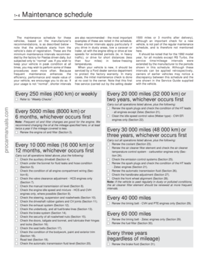 5
5 6
6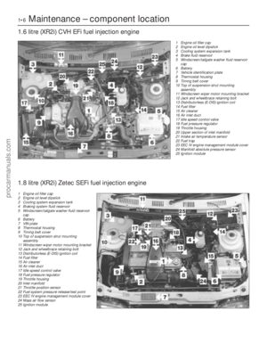 7
7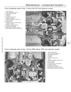 8
8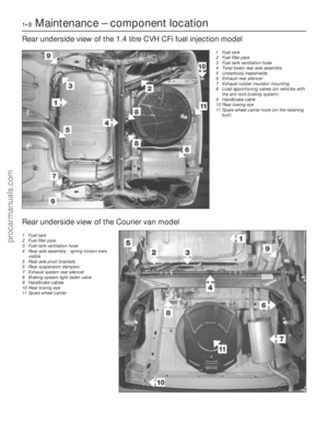 9
9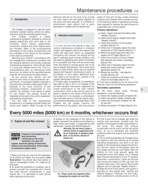 10
10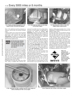 11
11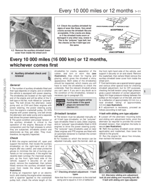 12
12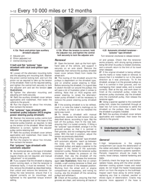 13
13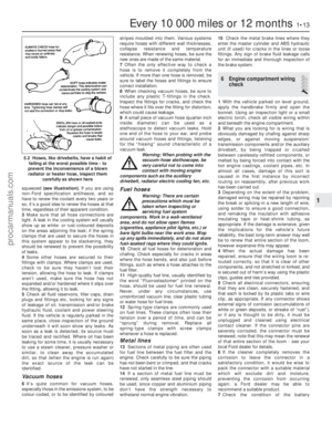 14
14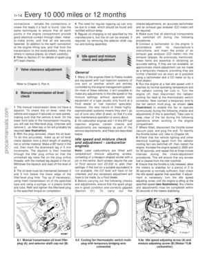 15
15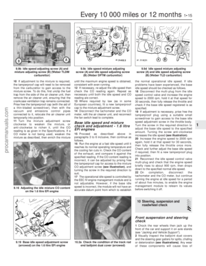 16
16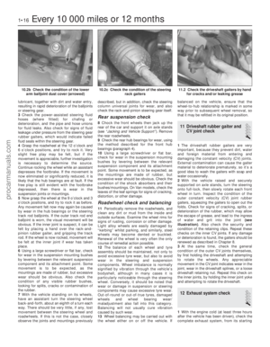 17
17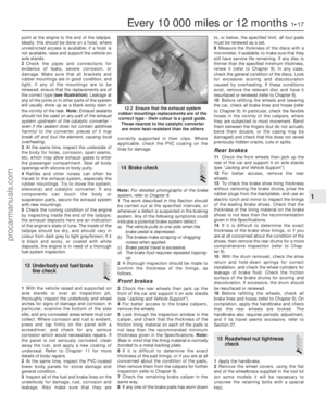 18
18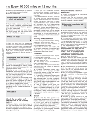 19
19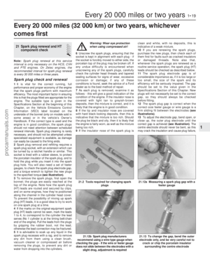 20
20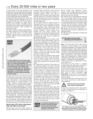 21
21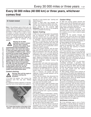 22
22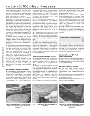 23
23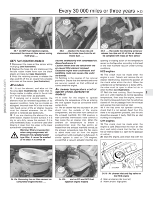 24
24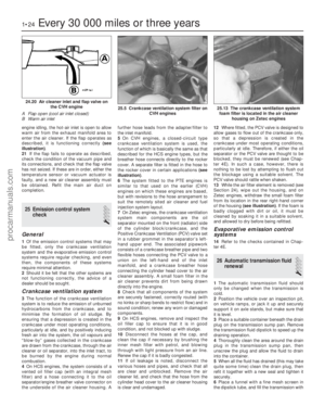 25
25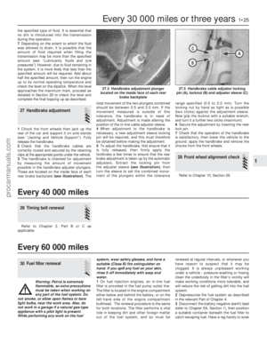 26
26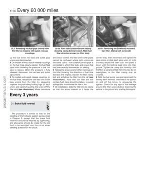 27
27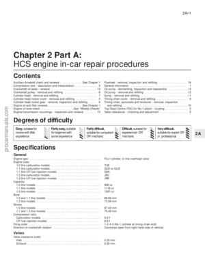 28
28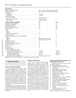 29
29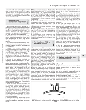 30
30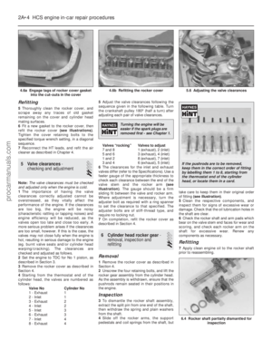 31
31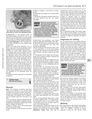 32
32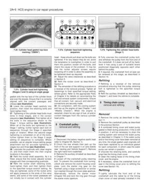 33
33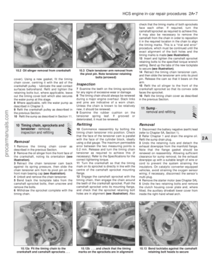 34
34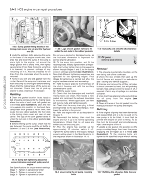 35
35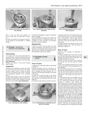 36
36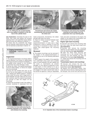 37
37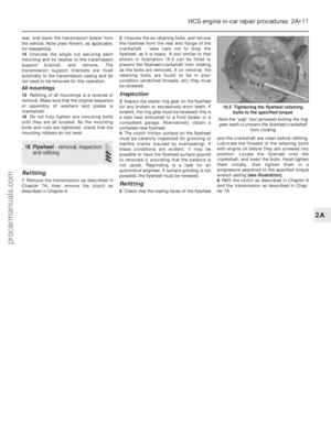 38
38 39
39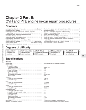 40
40 41
41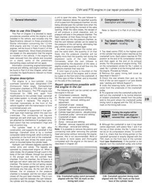 42
42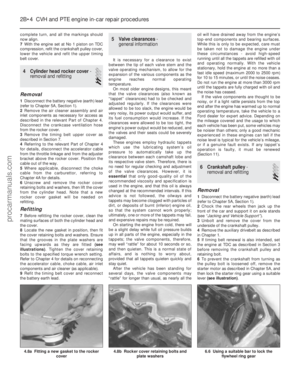 43
43 44
44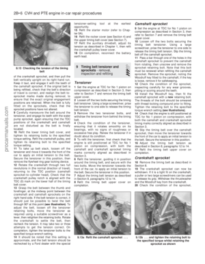 45
45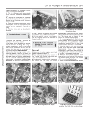 46
46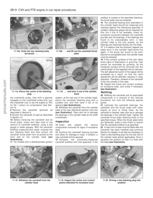 47
47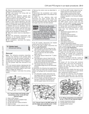 48
48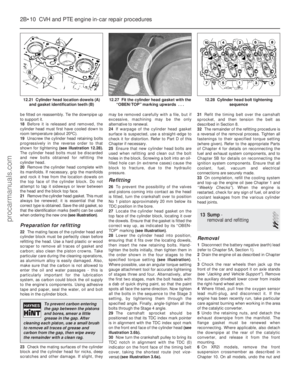 49
49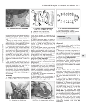 50
50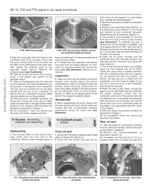 51
51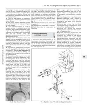 52
52 53
53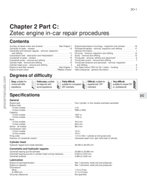 54
54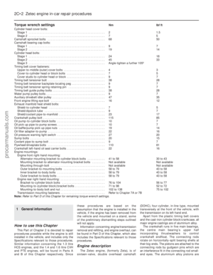 55
55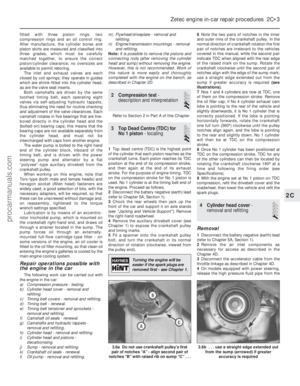 56
56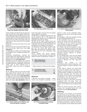 57
57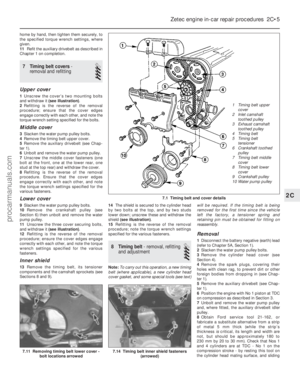 58
58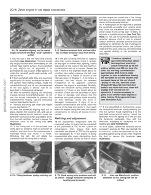 59
59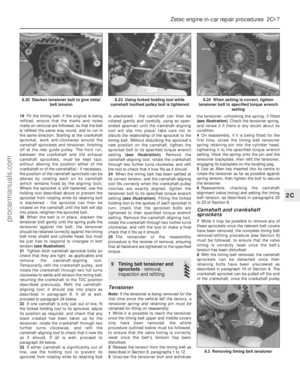 60
60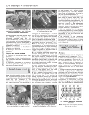 61
61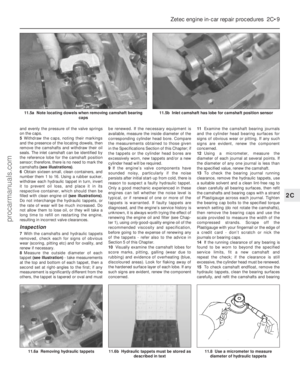 62
62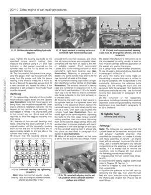 63
63 64
64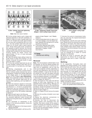 65
65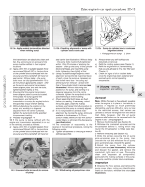 66
66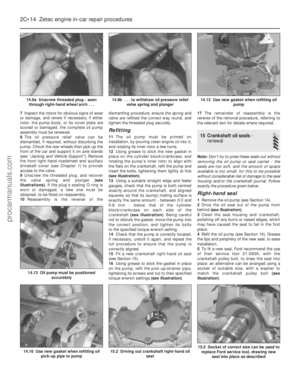 67
67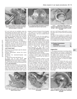 68
68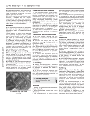 69
69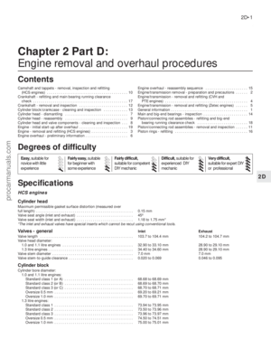 70
70 71
71 72
72 73
73 74
74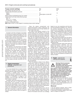 75
75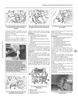 76
76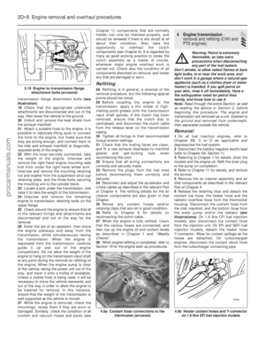 77
77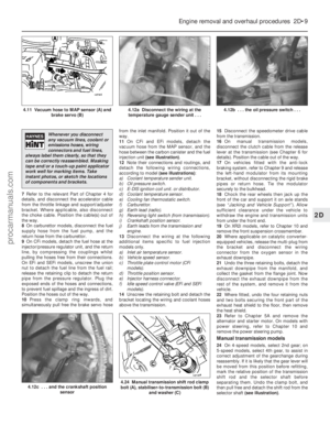 78
78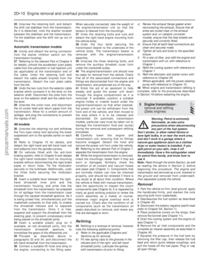 79
79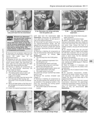 80
80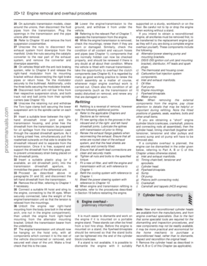 81
81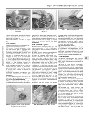 82
82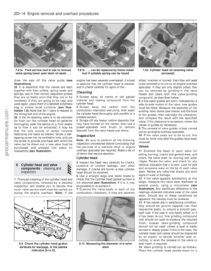 83
83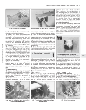 84
84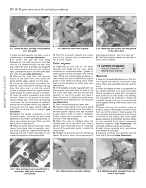 85
85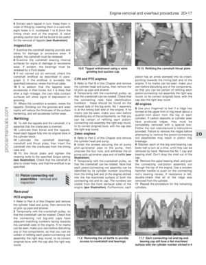 86
86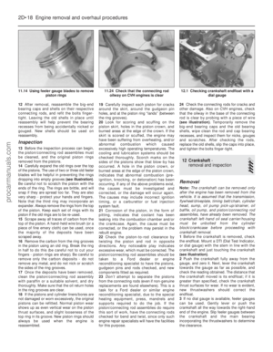 87
87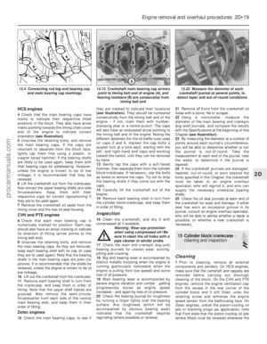 88
88 89
89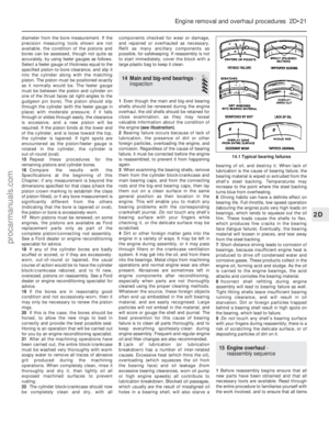 90
90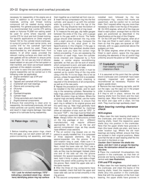 91
91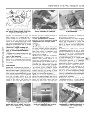 92
92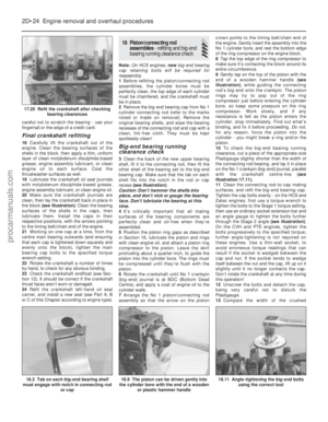 93
93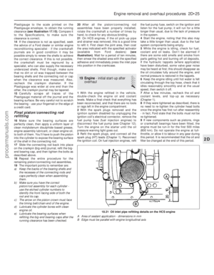 94
94 95
95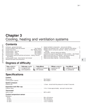 96
96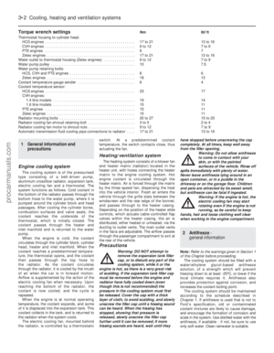 97
97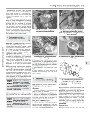 98
98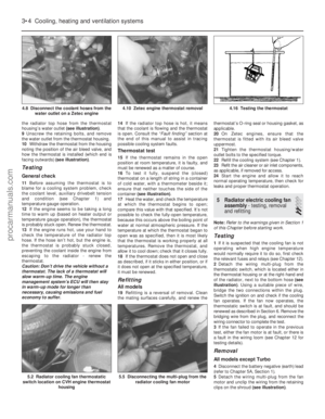 99
99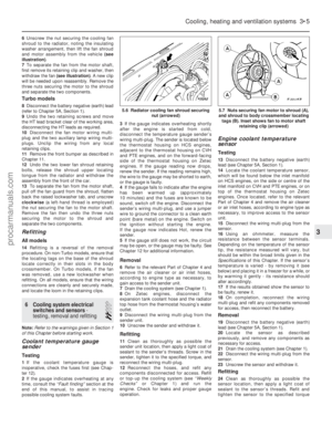 100
100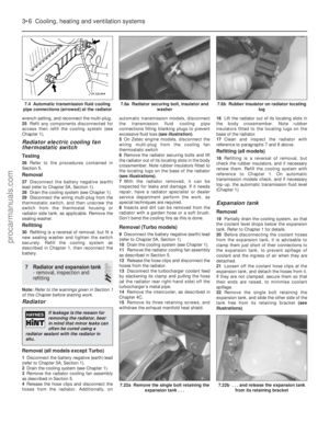 101
101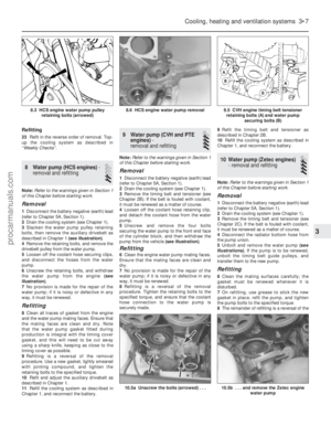 102
102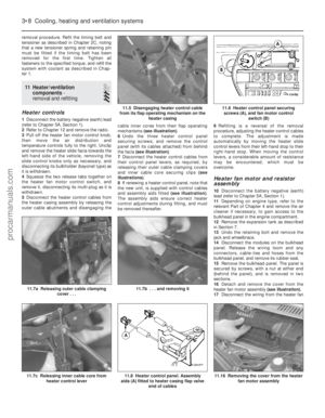 103
103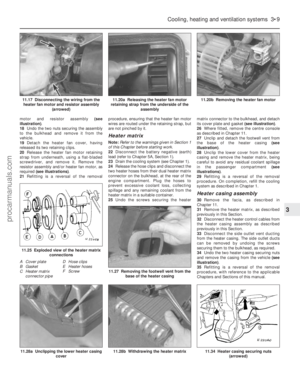 104
104 105
105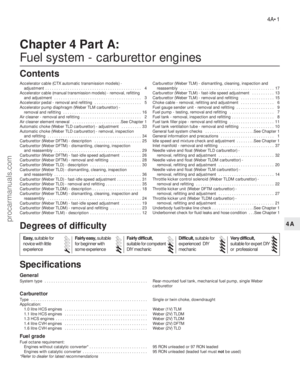 106
106 107
107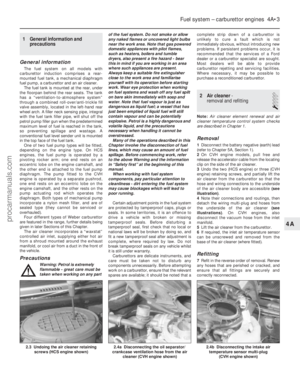 108
108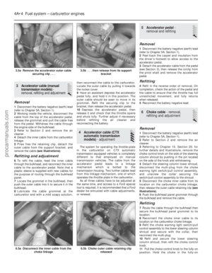 109
109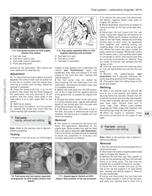 110
110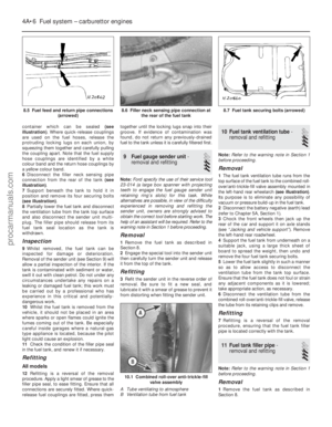 111
111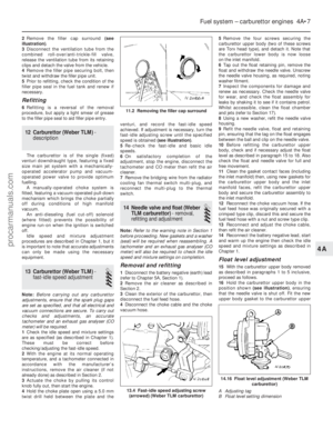 112
112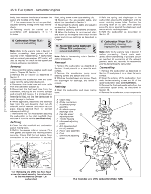 113
113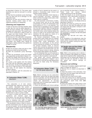 114
114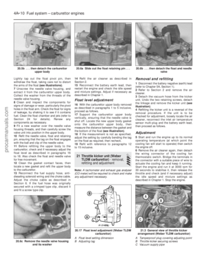 115
115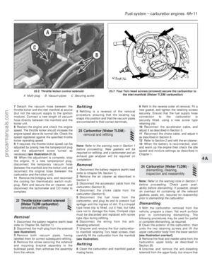 116
116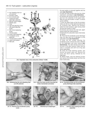 117
117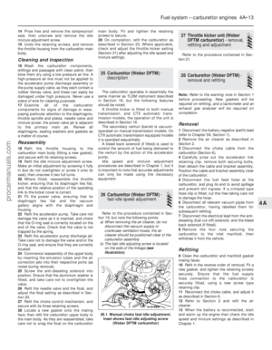 118
118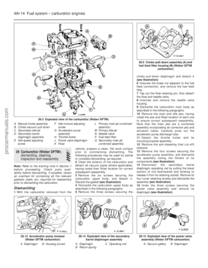 119
119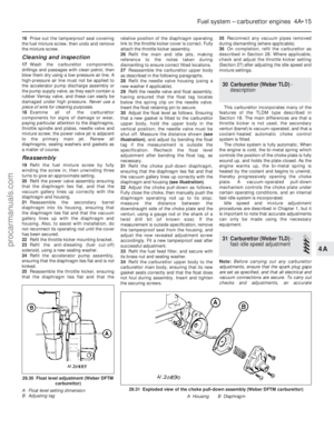 120
120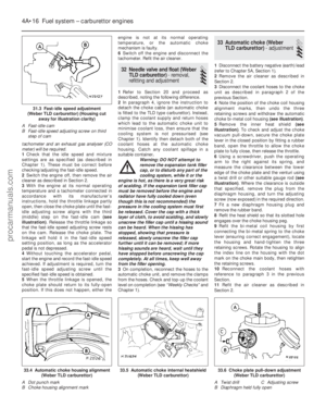 121
121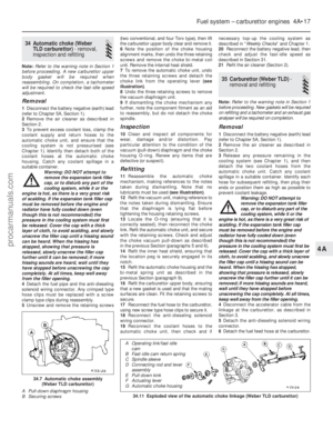 122
122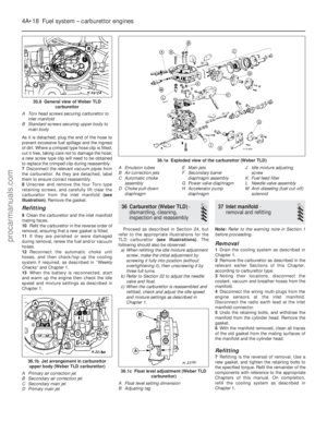 123
123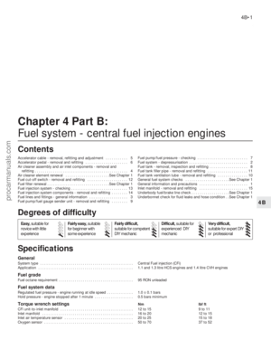 124
124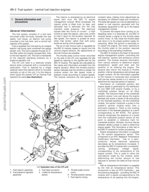 125
125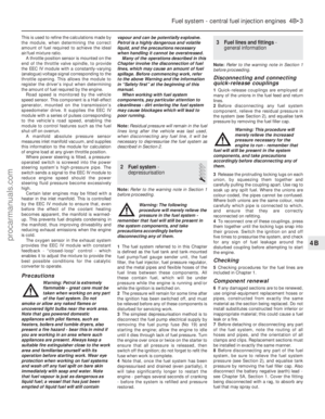 126
126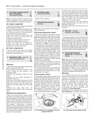 127
127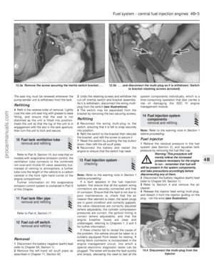 128
128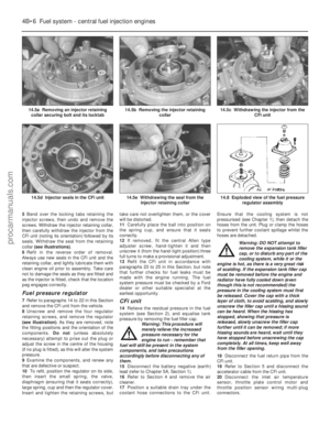 129
129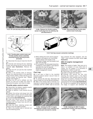 130
130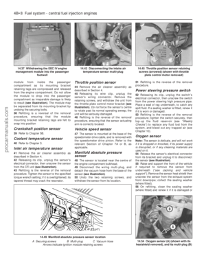 131
131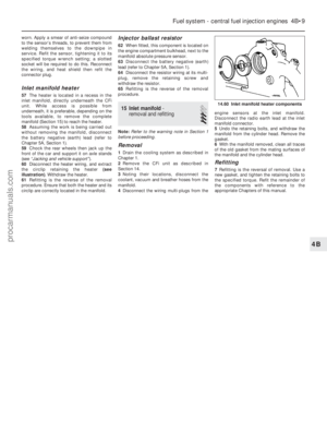 132
132 133
133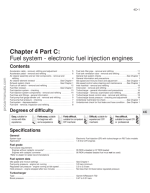 134
134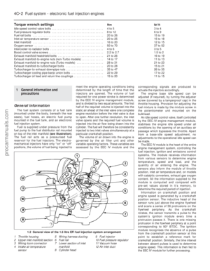 135
135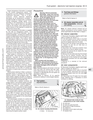 136
136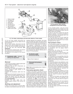 137
137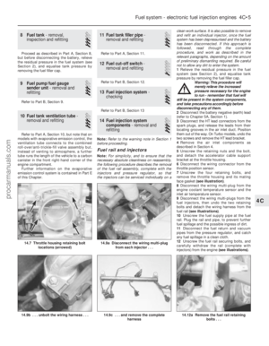 138
138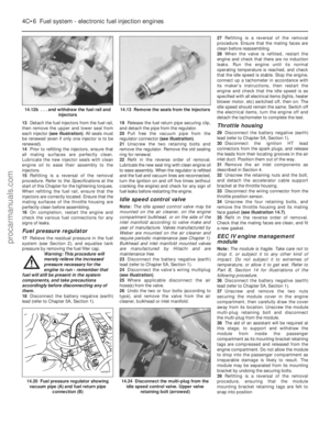 139
139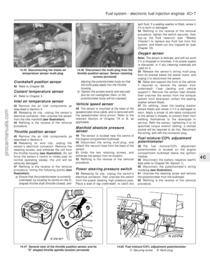 140
140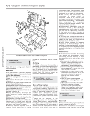 141
141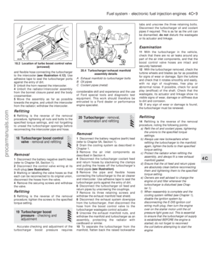 142
142 143
143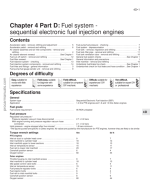 144
144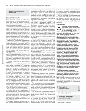 145
145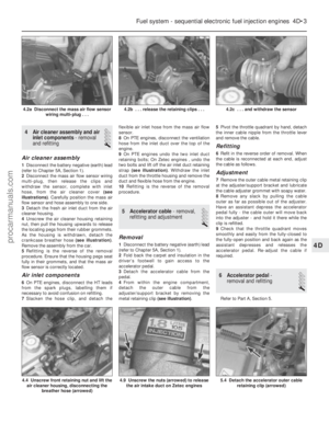 146
146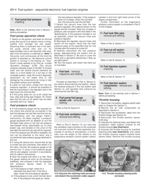 147
147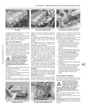 148
148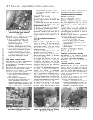 149
149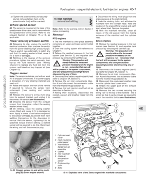 150
150 151
151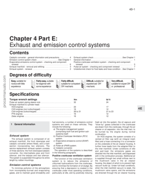 152
152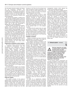 153
153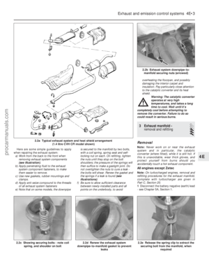 154
154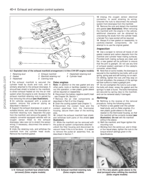 155
155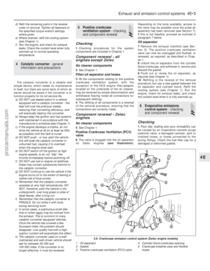 156
156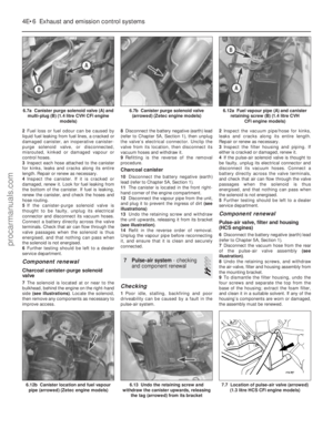 157
157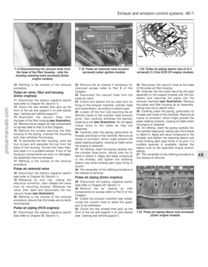 158
158 159
159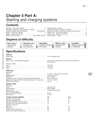 160
160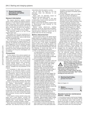 161
161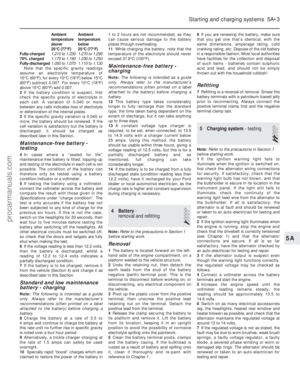 162
162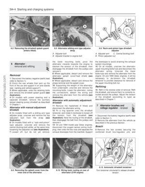 163
163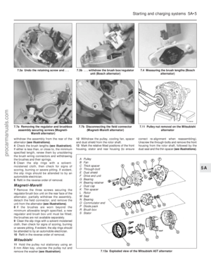 164
164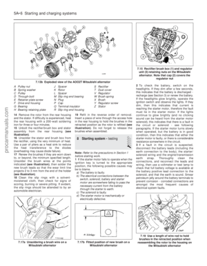 165
165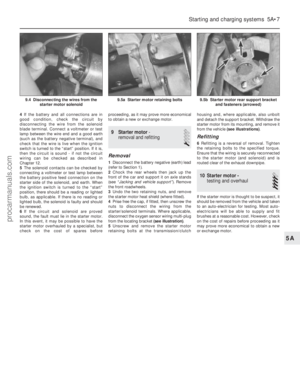 166
166 167
167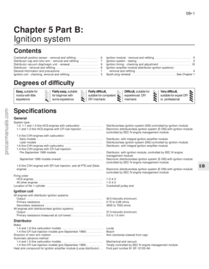 168
168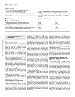 169
169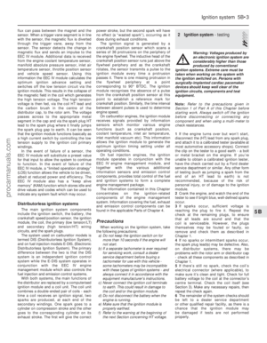 170
170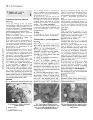 171
171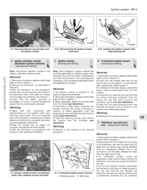 172
172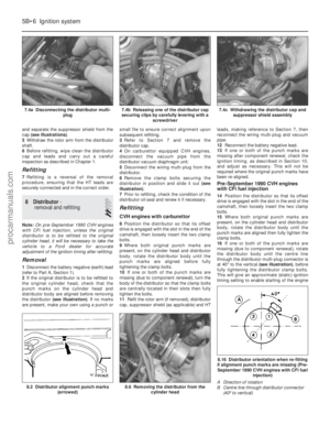 173
173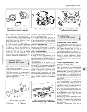 174
174 175
175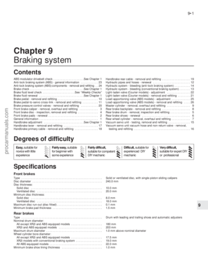 176
176 177
177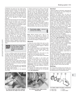 178
178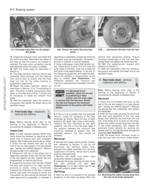 179
179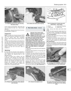 180
180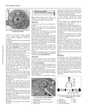 181
181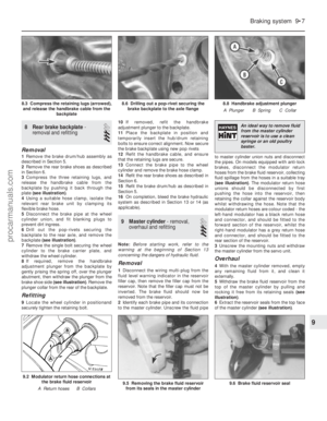 182
182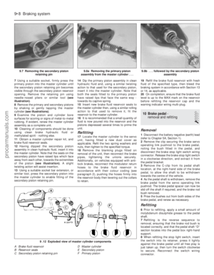 183
183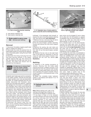 184
184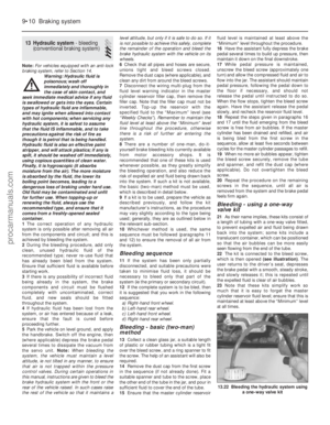 185
185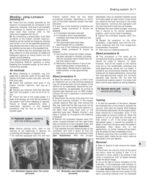 186
186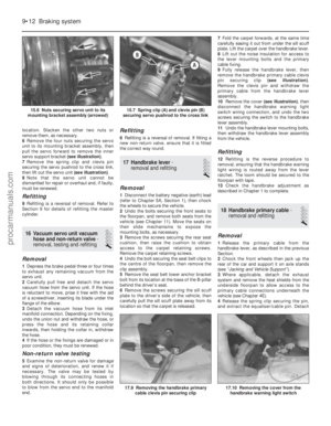 187
187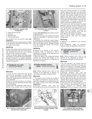 188
188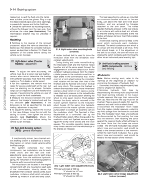 189
189 190
190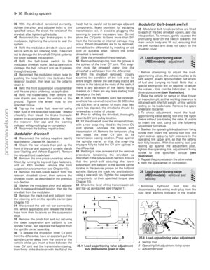 191
191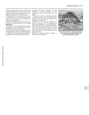 192
192 193
193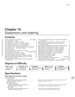 194
194 195
195 196
196 197
197 198
198 199
199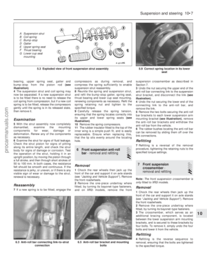 200
200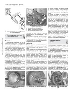 201
201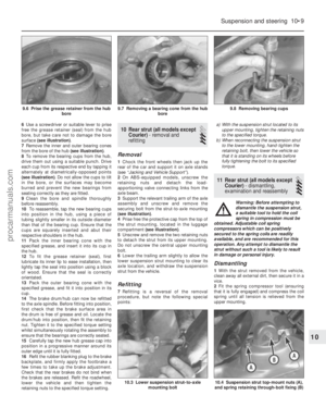 202
202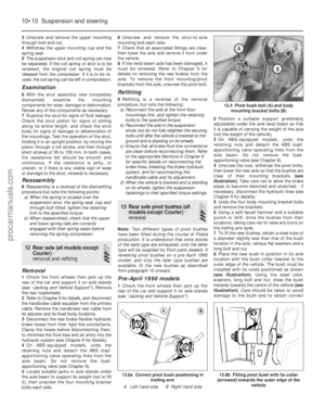 203
203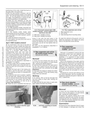 204
204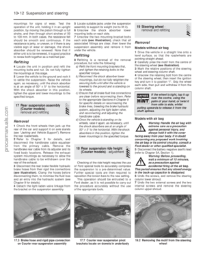 205
205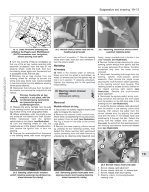 206
206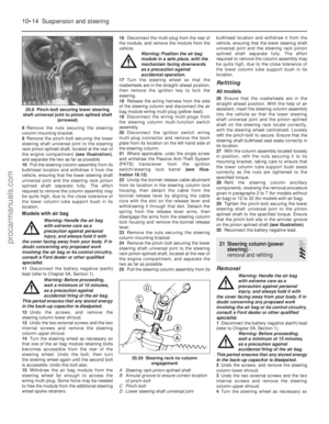 207
207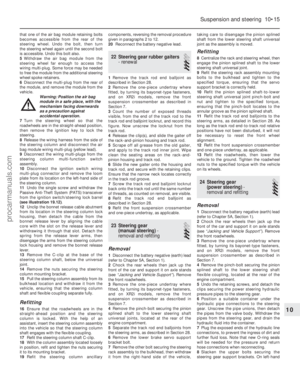 208
208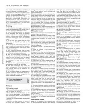 209
209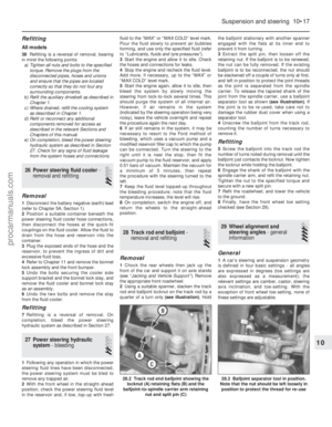 210
210 211
211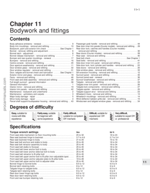 212
212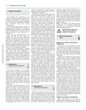 213
213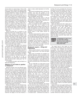 214
214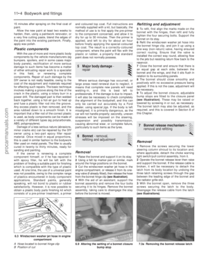 215
215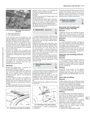 216
216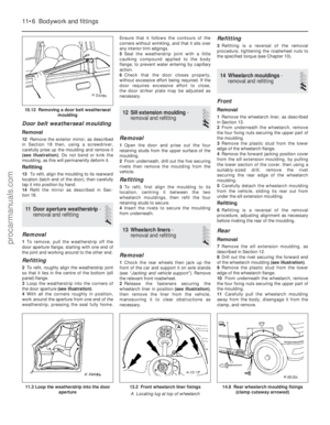 217
217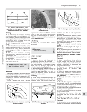 218
218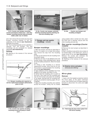 219
219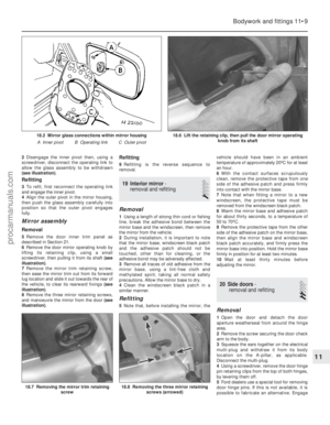 220
220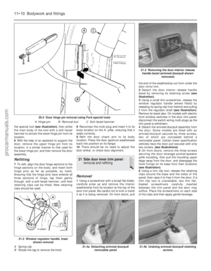 221
221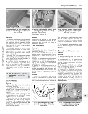 222
222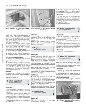 223
223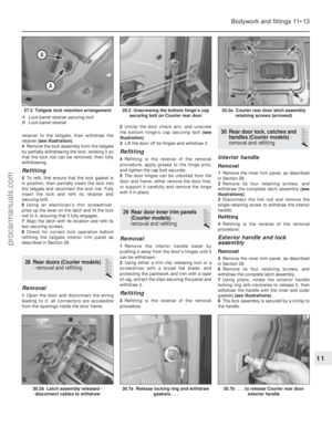 224
224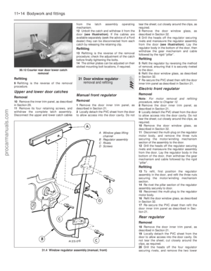 225
225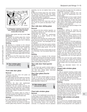 226
226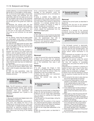 227
227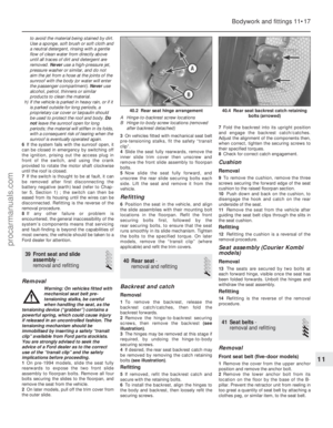 228
228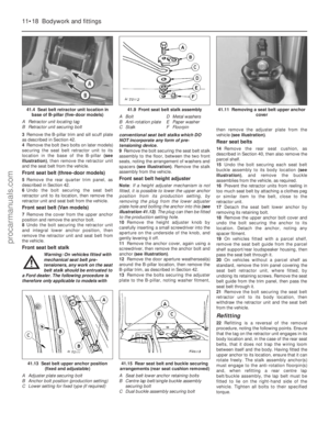 229
229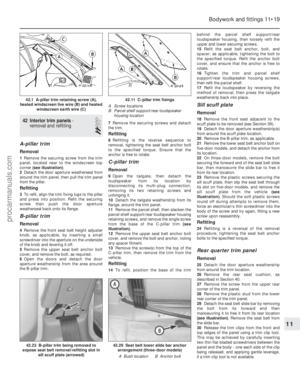 230
230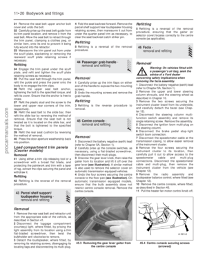 231
231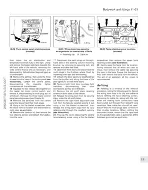 232
232 233
233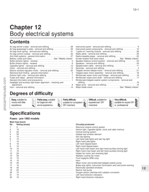 234
234 235
235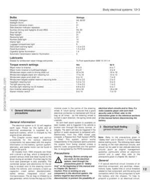 236
236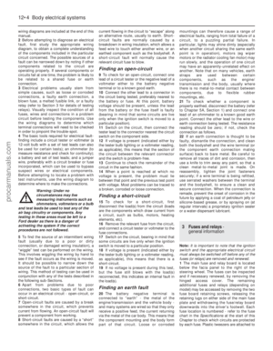 237
237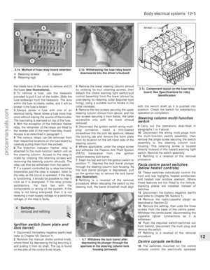 238
238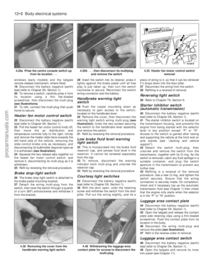 239
239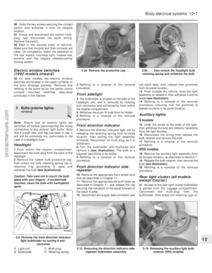 240
240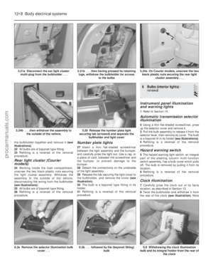 241
241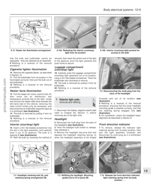 242
242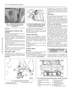 243
243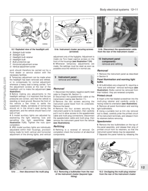 244
244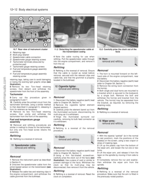 245
245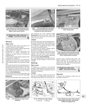 246
246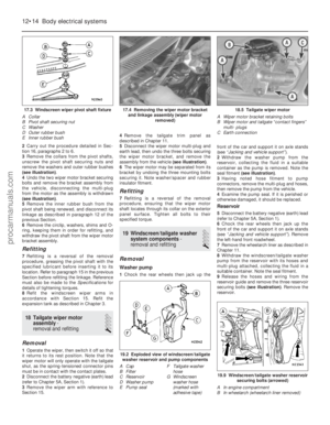 247
247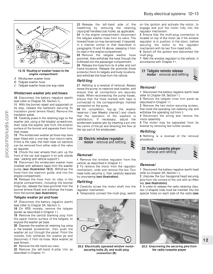 248
248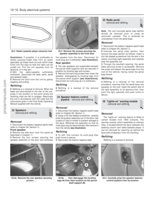 249
249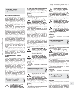 250
250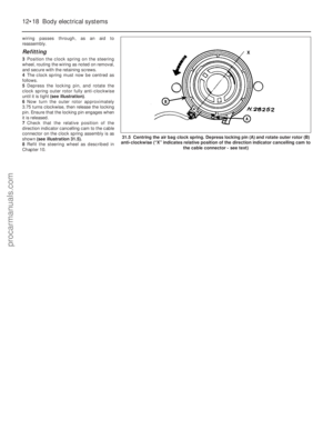 251
251 252
252 253
253 254
254 255
255 256
256 257
257 258
258 259
259 260
260 261
261 262
262 263
263 264
264 265
265 266
266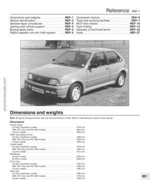 267
267 268
268 269
269 270
270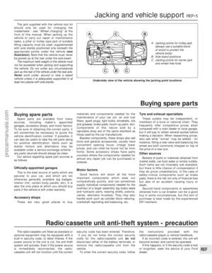 271
271 272
272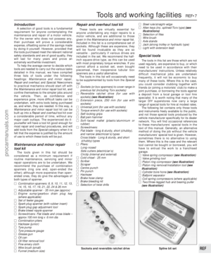 273
273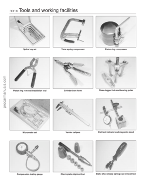 274
274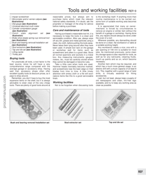 275
275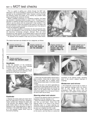 276
276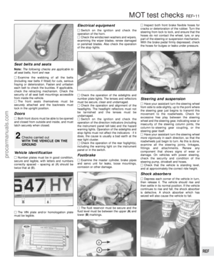 277
277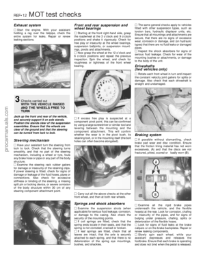 278
278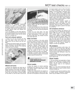 279
279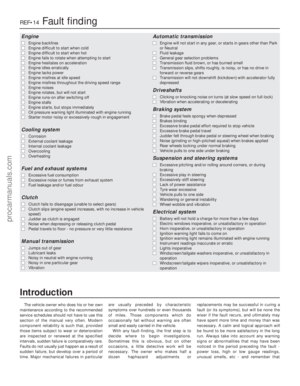 280
280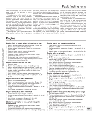 281
281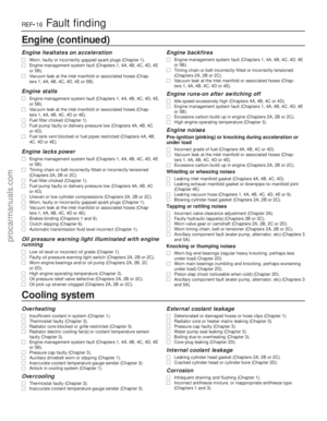 282
282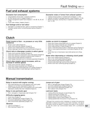 283
283 284
284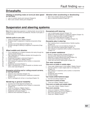 285
285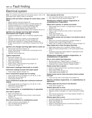 286
286 287
287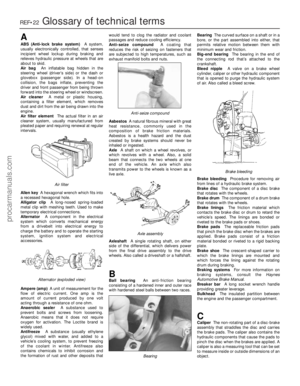 288
288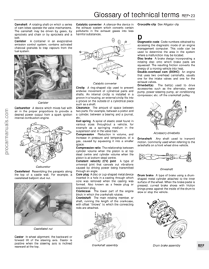 289
289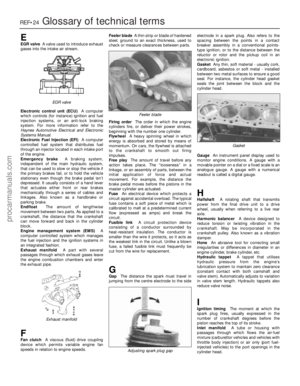 290
290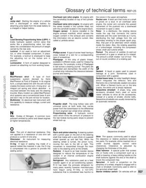 291
291 292
292 293
293 294
294 295
295