Page 97 of 296

Torque wrench settingsNmlbf ft
Thermostat housing to cylinder head: HCS engines . . . . . . . . . . . . . . . . . . . . . . . . . . . . . . . . . . . .\
. . . . . . . . 17 to 21 13 to 16
CVH engines . . . . . . . . . . . . . . . . . . . . . . . . . . . . . . . . . . . .\
. . . . . . . . 9 to 12 7 to 9
PTE engines . . . . . . . . . . . . . . . . . . . . . . . . . . . . . . . . . . . .\
. . . . . . . . 9 7
Zetec engines . . . . . . . . . . . . . . . . . . . . . . . . . . . . . . . . . . . .\
. . . . . . . 17 to 21 13 to 16
Water outlet to thermostat housing (Zetec engines) . . . . . . . . . . . . . . . 9 to 12 7 to 9
Water pump pulley . . . . . . . . . . . . . . . . . . . . . . . . . . . . . . . . . . . .\
. . . . . 107.5
Water pump retaining bolts: HCS, CVH and PTE engines . . . . . . . . . . . . . . . . . . . . . . . . . . . . . . . . 8 6
Zetec engines . . . . . . . . . . . . . . . . . . . . . . . . . . . . . . . . . . . .\
. . . . . . . 1813
Coolant temperature gauge sender . . . . . . . . . . . . . . . . . . . . . . . . . . . . 6 4
Coolant temperature sensor: HCS engines . . . . . . . . . . . . . . . . . . . . . . . . . . . . . . . . . . . .\
. . . . . . . . 2317
CVH engines: 1.4 litre models . . . . . . . . . . . . . . . . . . . . . . . . . . . . . . . . . . . .\
. . . . 1914
1.6 litre models . . . . . . . . . . . . . . . . . . . . . . . . . . . . . . . . . . . .\
. . . . 1511
PTE engines . . . . . . . . . . . . . . . . . . . . . . . . . . . . . . . . . . . .\
. . . . . . . . 1511
Zetec engines . . . . . . . . . . . . . . . . . . . . . . . . . . . . . . . . . . . .\
. . . . . . . 1511
Radiator mounting bolts . . . . . . . . . . . . . . . . . . . . . . . . . . . . . . . . . . . .\
. 20 to 27 15 to 20
Radiator cooling fan shroud retaining bolt . . . . . . . . . . . . . . . . . . . . . . . 3 to 5 2 to 4
Radiator cooling fan motor to shroud nuts . . . . . . . . . . . . . . . . . . . . . . . 9 to 12 7 to 9
Automatic transmission fluid cooling pipe connections to radiator . . . . 17 to 21 13 to 16
3•2 Cooling, heating and ventilation systems
1595Ford Fiesta Remake
1 General information and
precautions
Engine cooling system
The cooling system is of the pressurised
type consisting of a belt-driven pump,
aluminium crossflow radiator, expansion tank,
electric cooling fan and a thermostat. The
system functions as follows. Cold coolant in
the bottom of the radiator passes through the
bottom hose to the water pump, where it is
pumped around the cylinder block and head
passages. After cooling the cylinder bores,
combustion surfaces and valve seats, the
coolant reaches the underside of the
thermostat, which is initially closed. The
coolant passes through the heater and
inlet manifold and is returned to the water
pump. When the engine is cold, the coolant
circulates through the cylinder block, cylinder
head, heater and inlet manifold. When the
coolant reaches a predetermined tempera-
ture, the thermostat opens, and the coolant
then passes through the top hose to
the radiator. As the coolant circulates
through the radiator, it is cooled by the inrush
of air when the car is in forward motion.
Airflow is supplemented by the action of the
electric cooling fan when necessary. Upon
reaching the bottom of the radiator, the
coolant is now cooled, and the cycle is
repeated. When the engine is at normal operating
temperature, the coolant expands, and some
of it is displaced into the expansion tank. This
coolant collects in the tank, and is returned to
the radiator when the system cools.
The electric cooling fan, mounted behind
the radiator, is controlled by a thermostatic switch. At a predetermined coolant
temperature, the switch contacts close, thus
actuating the fan.
Heating/ventilation system
The heating system consists of a blower fan
and heater matrix (radiator) located in the
heater unit, with hoses connecting the heater
matrix to the engine cooling system. Hot
engine coolant is circulated through the
heater matrix. Air is forced through the matrix
by the three-speed fan, dispersing the heat
into the vehicle interior. Fresh air enters the
vehicle through the grille slats between the
windscreen and the rear edge of the bonnet,
and passes through to the heater casing.
Depending on the position of the heater slide
controls, which actuate cable-controlled flap
valves within the heater casing, the air is
distributed, either heated or unheated, via the
ducting to outlet vents. The main outlet vents
in the facia are adjustable. The airflow passes
through the passenger compartment to exit at
the rear of the vehicle.
Precautions
Warning: DO NOT attempt to
remove the expansion tank filler
cap, or to disturb any part of the
cooling system, while it or the
engine is hot, as there is a very great risk
of scalding. If the expansion tank filler cap
must be removed before the engine and
radiator have fully cooled down (even
though this is not recommended) the
pressure in the cooling system must first
be released. Cover the cap with a thick
layer of cloth, to avoid scalding, and slowly
unscrew the filler cap until a hissing sound
can be heard. When the hissing has
stopped, showing that pressure is
released, slowly unscrew the filler cap
further until it can be removed; if more
hissing sounds are heard, wait until they have stopped before unscrewing the cap
completely. At all times, keep well away
from the filler opening.
Warning: Do not allow antifreeze
to come in contact with your
skin, or with the painted
surfaces of the vehicle. Rinse off
spills immediately with plenty of water.
Never leave antifreeze lying around in an
open container, or in a puddle in the
driveway or on the garage floor. Children
and pets are attracted by its sweet smell,
but antifreeze can be fatal if ingested. Warning: If the engine is hot, the
electric cooling fan may start
rotating even if the engine is not
running, so be careful to keep
hands, hair and loose clothing well clear
when working in the engine compartment.
2 Antifreeze -
general information
Note: Refer to the warnings given in Section 1
of this Chapter before proceeding. The cooling system should be filled with a
water/ethylene glycol-based antifreeze
solution, of a strength which will prevent
freezing down to at least -25ºC, or lower if the
local climate requires it. Antifreeze also
provides protection against corrosion, and
increases the coolant boiling point. The cooling system should be maintained
according to the schedule described in
Chapter 1. If antifreeze is used that is not to
Ford’s specification, old or contaminated
coolant mixtures are likely to cause damage,
and encourage the formation of corrosion and
scale in the system. Use distilled water with the
antifreeze, if available - if not, be sure to use
only soft water. Clean rainwater is suitable.
procarmanuals.com
http://vnx.su
Page 98 of 296

Before adding antifreeze, check all hoses
and hose connections, because antifreeze
tends to leak through very small openings.
Engines don’t normally consume coolant, so if
the level falls regularly, find the cause and
correct it. The exact mixture of antifreeze-to-water
which you should use depends on the relative
weather conditions. The mixture should
contain at least 40% antifreeze, but not more
than 70%. Consult the mixture ratio chart on
the antifreeze container before adding
coolant. Hydrometers are available at most
automotive accessory shops to test the
coolant. Use only good-quality ethylene-
glycol-based antifreeze which meets the
vehicle manufacturer’s specifications.
3 Cooling system hoses -
disconnection and renewal
1
Note: Refer to the warnings given in Section 1
of this Chapter before starting work.
1 If the checks described in Chapter 1 reveal
a faulty hose, it must be renewed as follows.
2 First drain the cooling system (see Chap-
ter 1); if the antifreeze is not due for renewal,
the drained coolant may be re-used, if it is
collected in a clean container.
3 To disconnect any hose, use a pair of pliers
to release the spring clamps (or a screwdriver
to slacken screw-type clamps), then move
them along the hose clear of the union.
Carefully work the hose off its stubs. The
hoses can be removed with relative ease
when new - on an older car, they may have
stuck.
4 If a hose proves stubborn, try to release it
by rotating it on its unions before attempting
to work it off. Gently prise the end of the hose
with a blunt instrument (such as a flat-bladed
screwdriver), but do not apply too much force,
and take care not to damage the pipe stubs or
hoses. Note in particular that the radiator hose
unions are fragile; do not use excessive force
when attempting to remove the hoses.
5 When refitting a hose, first slide the clamps
onto the hose, then work the hose onto its
unions. 6
Work each hose end fully onto its union,
then check that the hose is settled correctly
and is properly routed. Slide each clip along
the hose until it is behind the union flared end,
before tightening it securely.
7 Refill the system with coolant (see Chap-
ter 1).
8 Check carefully for leaks as soon as
possible after disturbing any part of the
cooling system.
4 Thermostat -
removal, testing and refitting
1
Note: Refer to the warnings given in Section 1
of this Chapter before starting work.
Removal
1 Disconnect the battery negative (earth) lead
(refer to Chapter 5A, Section 1).
2 Drain the cooling system (see Chapter 1).
3 Refer to the relevant Part of Chapter 4 and
remove the air cleaner or air inlet hoses,
according to engine type as necessary, to
gain access to the thermostat housing.
HCS, CVH and PTE engines
4 Loosen the clips, and disconnect the
radiator top hose, expansion tank hose and,
where applicable, the heater hose from the
thermostat housing (see illustrations).5
Disconnect the thermostatic switch wire
multi-plug from the thermostat housing.
6 Unscrew the retaining bolts, and remove
the thermostat housing (see illustration).
7 Remove the gasket from the mating face of
the thermostat housing, then using suitable
pliers, compress the thermostat retaining clip
(where applicable) and remove it from the
housing. Extract the thermostat from
the housing (noting its direction of fitting) and
where applicable, remove the O-ring seal (see
illustrations) .
Zetec engines
8Disconnect the expansion tank hose and
Cooling, heating and ventilation systems 3•3
4.4b Disconnecting the expansion tank
top hose from the thermostat housing
(HCS engine). Radiator cooling fan thermal switch (arrowed)4.4a Thermostat housing hose
attachments on the CVH engine
4.7b Exploded view of thermostat and housing (CVH and PTE engines)
A Sealing ring C Retaining clip
B Thermostat
4.7a Removing the gasket and thermostat from an HCS engine4.6 Removing the thermostat housingfrom a CVH engine
3
1595Ford Fiesta Remake
If all else fails, cut the hose
with a sharp knife, then slit
it so that it can be peeled off
in two pieces. Although this
may prove expensive if the hose is
otherwise undamaged, it is preferable
to buying a new radiator.
If the hose is stiff, use a little
soapy water as a lubricant,
or soften the hose by
soaking it in hot water. Do
not use oil or grease, which may attack
the rubber.
procarmanuals.com
http://vnx.su
Page 99 of 296
.
9 Unscrew the retaining bolts, and remove
the water outlet from the thermostat housing.
10 Withdraw the thermosta")
the radiator top hose from the thermostat
housing’s water outlet (see illustration).
9 Unscrew the retaining bolts, and remove
the water outlet from the thermostat housing.
10 Withdraw the thermostat from the housing
noting the position of the air bleed valve, and
how the thermostat is installed (which end is
facing outwards) (see illustration).
Testing
General check
11Before assuming the thermostat is to
blame for a cooling system problem, check
the coolant level, auxiliary drivebelt tension
and condition (see Chapter 1) and
temperature gauge operation.
12 If the engine seems to be taking a long
time to warm up (based on heater output or
temperature gauge operation), the thermostat
is probably stuck open. Renew the thermostat.
13 If the engine runs hot, use your hand to
check the temperature of the radiator top
hose. If the hose isn’t hot, but the engine is,
the thermostat is probably stuck closed,
preventing the coolant inside the engine from
escaping to the radiator - renew the
thermostat.
Caution: Don’t drive the vehicle without a
thermostat. The lack of a thermostat will
slow warm-up time. The engine
management system’s ECU will then stay
in warm-up mode for longer than
necessary, causing emissions and fuel
economy to suffer. 14
If the radiator top hose is hot, it means
that the coolant is flowing and the thermostat
is open. Consult the “Fault finding” section at
the end of this manual to assist in tracing
possible cooling system faults.
Thermostat test
15 If the thermostat remains in the open
position at room temperature, it is faulty, and
must be renewed as a matter of course.
16 To test it fully, suspend the (closed)
thermostat on a length of string in a container
of cold water, with a thermometer beside it;
ensure that neither touches the side of the
container (see illustration) .
17 Heat the water, and check the temperature
at which the thermostat begins to open;
compare this value with that specified. It’s not
possible to check the fully-open temperature,
because this occurs above the boiling point of
water at normal atmospheric pressure. If the
temperature at which the thermostat began to
open was as specified, then it is most likely
that the thermostat is working properly at all
temperatures. Remove the thermostat, and
allow it to cool down; check that it closes fully.
18 If the thermostat does not open and close
as described, if it sticks in either position, or if
it does not open at the specified temperature,
it must be renewed.
Refitting
All models
19 Refitting is a reversal of removal. Clean
the mating surfaces carefully, and renew the thermostat’s O-ring seal or housing gasket, as
applicable.
20
On Zetec engines, ensure that the
thermostat is fitted with its air bleed valve
uppermost.
21 Tighten the thermostat housing/water
outlet bolts to the specified torque.
22 Refill the cooling system (see Chapter 1).
23 Refit the air cleaner or air inlet components,
as applicable, if removed for access.
24 Start the engine and allow it to reach
normal operating temperature, then check for
leaks and proper thermostat operation.
5 Radiator electric cooling fan assembly - testing, removal
and refitting
2
Note: Refer to the warnings given in Section 1
of this Chapter before starting work.
Testing
1 If it is suspected that the cooling fan is not
operating when high engine temperature
would normally require it to do so, first check
the relevant fuses and relays (see Chapter 12).
2 Detach the wiring multi-plug from the
thermostatic switch, which is located either in
the thermostat housing or at the right-hand end
of the radiator, next to the bottom hose (see
illustration) . Using a suitable piece of wire,
bridge the two connections within the plug.
Switch the ignition on and check if the cooling
fan operates. If the fan now operates, the
thermostatic switch is at fault, and should be
renewed as described in Section 6. Remove the
bridging wire from the plug, and reconnect the
wiring connector to complete the test.
3 If the fan failed to operate in the previous
test, either the fan motor is at fault, or there is
a fault in the wiring loom (see Chapter 12 for
testing details).
Removal
All models except Turbo
4 Disconnect the battery negative (earth) lead
(refer to Chapter 5A, Section 1).
5 Detach the wiring multi-plug from the fan
motor and unclip the wiring from the retaining
clips on the shroud (see illustration).
3•4 Cooling, heating and ventilation systems
5.5 Disconnecting the multi-plug from the
radiator cooling fan motor5.2 Radiator cooling fan thermostatic
switch location on CVH engine thermostat
housing
4.16 Testing the thermostat4.10 Zetec engine thermostat removal4.8 Disconnect the coolant hoses from thewater outlet on a Zetec engine
1595Ford Fiesta Remakeprocarmanuals.com
http://vnx.su
Page 100 of 296
 .
7 To sepa")
6Unscrew the nut securing the cooling fan
shroud to the radiator, noting the insulating
washer arrangement, then lift the fan shroud
and motor assembly from the vehicle (see
illustration) .
7 To separate the fan from the motor shaft,
first remove its retaining clip and washer, then
withdraw the fan (see illustration) . A new clip
will be needed upon reassembly. Remove the
three nuts securing the motor to the shroud
and separate the two components.
Turbo models
8 Disconnect the battery negative (earth) lead
(refer to Chapter 5A, Section 1).
9 Undo the two retaining screws and move
the HT lead bracket clear of the working area,
disconnecting the HT leads as required.
10 Disconnect the fan motor wiring multi-
plug and the two auxiliary lamp wiring multi-
plugs. Unclip the wiring from any local
retaining clips.
11 Remove the front bumper as described in
Chapter 11.
12 Undo the two lower fan shroud retaining
bolts, release the shroud upper locating
tongue from the radiator and withdraw the
assembly from the front of the car.
13 To separate the fan from the motor shaft,
pull off the fan guard from the shroud, flatten
back the raised lockwasher tab, and unscrew
clockwise (a left-hand thread is employed)
the nut securing the fan to the motor shaft.
Remove the fan then undo the three nuts
securing the motor to the shroud and
separate the two components.
Refitting
All models
14 Refitting is a reversal of the removal
procedure. On non-Turbo models, ensure that
the locating tags on the base of the shroud
locate correctly in their slots in the body
crossmember. On Turbo models, if the fan
was removed, use a new lockwasher when
refitting. On all models, ensure that the wiring
connections are cleanly and securely made,
and locate the loom in the retaining clips.
6 Cooling system electrical switches and sensors -
testing, removal and refitting
2
Note: Refer to the warnings given in Section 1
of this Chapter before starting work.
Coolant temperature gauge
sender
Testing
1 If the coolant temperature gauge is
inoperative, check the fuses first (see Chap-
ter 12).
2 If the gauge indicates overheating at any
time, consult the “Fault finding” section at the
end of this manual, to assist in tracing
possible cooling system faults. 3
If the gauge indicates overheating shortly
after the engine is started from cold,
disconnect the temperature gauge sender’s
wiring multi-plug. The sender is located below
the thermostat housing on HCS engines,
adjacent to the thermostat housing on CVH
and PTE engines, and on the forward-facing
side of the thermostat housing on Zetec
engines. If the gauge reading now drops,
renew the sender. If the reading remains high,
the wire to the gauge may be shorted to earth,
or the gauge is faulty.
4 If the gauge fails to indicate after the engine
has been warmed up (approximately
10 minutes) and the fuses are known to be
sound, switch off the engine. Disconnect the
sender’s wiring multi-plug, and use a jumper
wire to ground the connector to a clean earth
point (bare metal) on the engine. Switch on
the ignition without starting the engine.
If the gauge now indicates Hot, renew the
sender.
5 If the gauge still does not work, the circuit
may be open, or the gauge may be faulty. See
Chapter 12 for additional information.
Removal
6 Refer to the relevant Part of Chapter 4 and
remove the air cleaner or air inlet hoses,
according to engine type as necessary, to
gain access to the sender unit.
7 Drain the cooling system (see Chapter 1).
8 On Zetec engines, disconnect the
expansion tank coolant hose and the radiator
top hose from the thermostat housing’s water
outlet.
9 Disconnect the wiring multi-plug from the
sender unit.
10 Unscrew the sender and withdraw it.
Refitting
11Clean as thoroughly as possible the
sender unit location, then apply a light coat of
sealant to the sender’s threads. Screw in the
sender, tighten it to the specified torque, and
reconnect the wiring multi-plug.
12 Reconnect the hoses, and refit any
components disconnected for access. Refill
or top-up the cooling system (see “Weekly
Checks” or Chapter 1) and run the
engine. Check for leaks and proper gauge
operation.
Engine coolant temperature
sensor
Testing
13 Disconnect the battery negative (earth)
lead (see Chapter 5A, Section 1).
14 Locate the coolant temperature sensor,
which will be found below the inlet manifold
on HCS engines, on the side or centre of the
inlet manifold on CVH and PTE engines, or on
top of the thermostat housing on Zetec
engines. Once located, refer to the relevant
Part of Chapter 4 and remove the air cleaner
or air inlet hoses, according to engine type as
necessary, to improve access to the sensor
unit.
15 Disconnect the wiring multi-plug from the
sensor.
16 Using an ohmmeter, measure the
resistance between the sensor terminals.
Depending on the temperature of the sensor
tip, the resistance measured will vary, but
should be within the broad limits given in the
Specifications of this Chapter. If the sensor’s
temperature is varied - by removing it (see
below) and placing it in a freezer for a while, or
by warming it gently - its resistance should
alter accordingly.
17 If the results obtained show the sensor to
be faulty, renew it.
18 On completion, reconnect the wiring
multi-plug and refit any components removed
for access, then reconnect the battery.
Removal
19 Disconnect the battery negative (earth)
lead (see Chapter 5A, Section 1).
20 Locate the sensor as described
previously, and remove any components as
necessary for access.
21 Drain the cooling system (see Chapter 1).
22 Disconnect the wiring multi-plug from the
sensor.
23 Unscrew the sensor and withdraw it.
Refitting
24Clean as thoroughly as possible the
sensor location, then apply a light coat of
sealant to the sensor’s threads. Refit and
tighten the sensor to the specified torque
Cooling, heating and ventilation systems 3•5
5.7 Nuts securing fan motor to shroud (A),
and shroud to body crossmember locating tags (B). Inset shows fan to motor shaft retaining clip (arrowed)5.6 Radiator cooling fan shroud securing nut (arrowed)
3
1595Ford Fiesta Remakeprocarmanuals.com
http://vnx.su
Page 101 of 296
.
Radiator electric cooling fan
thermostatic switch
Testing
2")
wrench setting, and reconnect the multi-plug.
25Refit any components disconnected for
access then refill the cooling system (see
Chapter 1).
Radiator electric cooling fan
thermostatic switch
Testing
26 Refer to the procedures contained in
Section 5.
Removal
27 Disconnect the battery negative (earth)
lead (refer to Chapter 5A, Section 1).
28 Drain the cooling system (see Chapter 1).
29 Disconnect the wiring multi-plug from the
thermostatic switch, and then unscrew the
switch from the thermostat housing or
radiator side tank, as applicable. Remove the
sealing washer.
Refitting
30 Refitting is a reversal of removal, but fit a
new sealing washer and tighten the switch
securely. Refill the cooling system as
described in Chapter 1, then reconnect the
battery.
7 Radiator and expansion tank
- removal, inspection and
refitting
2
Note: Refer to the warnings given in Section 1
of this Chapter before starting work.
Radiator
Removal (all models except Turbo)
1 Disconnect the battery negative (earth) lead
(refer to Chapter 5A, Section 1).
2 Drain the cooling system (see Chapter 1).
3 Remove the radiator cooling fan assembly
as described in Section 5.
4 Release the hose clips and disconnect the
hoses from the radiator. Additionally, on automatic transmission models, disconnect
the transmission fluid cooling pipe
connections fitting blanking plugs to prevent
excessive fluid loss
(see illustration).
5 On Zetec engine models, disconnect the
wiring multi-plug from the cooling fan
thermostatic switch
6 Remove the radiator securing bolts and lift
the radiator out of its locating slots in the body
crossmember. Note rubber insulators fitted to
the locating lugs on the base of the radiator
(see illustrations) .
7 With the radiator removed, it can be
inspected for leaks and damage. If it needs
repair, have a radiator specialist or dealer
service department perform the work, as
special techniques are required.
8 Insects and dirt can be removed from the
radiator with a garden hose or a soft brush.
Don’t bend the cooling fins as this is done.
Removal (Turbo models)
9 Disconnect the battery negative (earth) lead
(refer to Chapter 5A, Section 1).
10 Drain the cooling system (see Chapter 1).
11 Remove the radiator cooling fan assembly
as described in Section 5.
12 Release the hose clips and disconnect the
hoses from the radiator.
13 Disconnect the turbocharger coolant feed
by slackening its clamp and pulling the hose
(at the radiator rear right-hand side) off the
turbocharger’s metal pipe.
14 Remove the intercooler, as described in
Chapter 4C.
15 Remove its three retaining screws, and
withdraw the exhaust manifold heat shield. 16
Lift the radiator out of its locating slots in
the body crossmember. Note rubber
insulators fitted to the locating lugs on the
base of the radiator.
17 Clean and inspect the radiator with
reference to paragraphs 7 and 8 above.
Refitting (all models)
18 Refitting is a reversal of removal, but
check the rubber insulators, and if necessary
renew them. Refill the cooling system with
reference to Chapter 1. On automatic
transmission models check, and if necessary
top-up, the automatic transmission fluid level
(Chapter 1).
Expansion tank
Removal
19 Partially drain the cooling system, so that
the coolant level drops below the expansion
tank. Refer to Chapter 1 for details.
20 Before disconnecting the coolant hoses
from the expansion tank, it is advisable to
clamp them just short of their connections to
the expansion tank, to prevent spillage of
coolant and the ingress of air when they are
detached.
21 Loosen off the coolant hose clips at the
expansion tank, and detach the hoses from it.
If they are not clamped, secure them so that
their ends are raised, to minimise coolant
spillage.
22 Remove the single bolt retaining the
expansion tank, and slide the other side of the
tank free from its retaining bracket (see
illustrations) .
3•6Cooling, heating and ventilation systems
7.22b . . . and release the expansion tank
from its retaining bracket7.22a Remove the single bolt retaining the expansion tank . . .
7.6b Rubber insulator on radiator locating lug7.6a Radiator securing bolt, insulator andwasher7.4 Automatic transmission fluid cooling
pipe connections (arrowed) at the radiator
1595Ford Fiesta Remake
If leakage is the reason for
removing the radiator, bear
in mind that minor leaks can
often be cured using a
radiator sealant with the radiator in
situ.
procarmanuals.com
http://vnx.su
Page 102 of 296
 -
removal and refitting
2
Note: Refer to the warnings give")
Refitting
23Refit in the reverse order of removal. Top-
up the cooling system as described in
“Weekly Checks”.
8 Water pump (HCS engines) -
removal and refitting
2
Note: Refer to the warnings given in Section 1
of this Chapter before starting work.
Removal
1 Disconnect the battery negative (earth) lead
(refer to Chapter 5A, Section 1).
2 Drain the cooling system (see Chapter 1).
3 Slacken the water pump pulley retaining
bolts, then remove the auxiliary drivebelt as
described in Chapter 1 (see illustration).
4 Remove the retaining bolts, and remove the
drivebelt pulley from the water pump.
5 Loosen off the coolant hose securing clips,
and disconnect the hoses from the water
pump.
6 Unscrew the retaining bolts, and withdraw
the water pump from the engine (see
illustration) .
7 No provision is made for the repair of the
water pump; if it is noisy or defective in any
way, it must be renewed.
Refitting
8 Clean all traces of gasket from the engine
and the water pump mating faces. Ensure that
the mating faces are clean and dry. Note
that the water pump gasket fitted during
production is integral with the timing cover
gasket, and this will need to be cut away
using a sharp knife, keeping as close to the
timing cover as possible.
9 Refitting is a reversal of the removal
procedure. Use a new gasket, lightly smeared
with jointing compound, and tighten the
retaining bolts to the specified torque.
10 Refit and adjust the auxiliary drivebelt as
described in Chapter 1.
11 Refill the cooling system as described in
Chapter 1, and reconnect the battery.
9 Water pump (CVH and PTE engines) -
removal and refitting
4
Note: Refer to the warnings given in Section 1
of this Chapter before starting work.
Removal
1 Disconnect the battery negative (earth) lead
(refer to Chapter 5A, Section 1).
2 Drain the cooling system (see Chapter 1).
3 Remove the timing belt and tensioner (see
Chapter 2B). If the belt is fouled with coolant,
it must be renewed as a matter of course.
4 Loosen off the coolant hose retaining clip,
and detach the coolant hose from the water
pump.
5 Unscrew and remove the four bolts
securing the water pump to the front end face
of the cylinder block, and then withdraw the
pump from the vehicle (see illustration).
Refitting
6Clean the engine water pump mating faces.
Ensure that the mating faces are clean and
dry.
7 No provision is made for the repair of the
water pump; if it is noisy or defective in any
way, it must be renewed.
8 Refitting is a reversal of the removal
procedure. Tighten the retaining bolts to the
specified torque, and ensure that the coolant
hose connection to the water pump is
securely made. 9
Refit the timing belt and tensioner as
described in Chapter 2B.
10 Refill the cooling system as described in
Chapter 1, and reconnect the battery.
10 Water pump (Zetec engines) - removal and refitting
4
Note: Refer to the warnings given in Section 1
of this Chapter before starting work.
Removal
1 Disconnect the battery negative (earth) lead
(refer to Chapter 5A, Section 1).
2 Drain the cooling system (see Chapter 1).
3 Remove the timing belt and tensioner (see
Chapter 2C). If the belt is fouled with coolant,
it must be renewed as a matter of course.
4 Disconnect the radiator bottom hose from
the pump union.
5 Unbolt and remove the water pump (see
illustrations) . If the pump is to be renewed,
unbolt the timing belt guide pulleys, and
transfer them to the new pump.
Refitting
6 Clean the mating surfaces carefully; the
gasket must be renewed whenever it is
disturbed.
7 On refitting, use grease to stick the new
gasket in place, refit the pump, and tighten
the pump bolts to the specified torque.
8 The remainder of refitting is a reversal of the
Cooling, heating and ventilation systems 3•7
9.5 CVH engine timing belt tensioner
retaining bolts (A) and water pump securing bolts (B)8.6 HCS engine water pump removal8.3 HCS engine water pump pulleyretaining bolts (arrowed)
10.5b . . . and remove the Zetec engine water pump10.5a Unscrew the bolts (arrowed) . . .
3
1595Ford Fiesta Remakeprocarmanuals.com
http://vnx.su
Page 103 of 296

removal procedure. Refit the timing belt and
tensioner as described in Chapter 2C, noting
that a new tensioner spring and retaining pin
must be fitted if the timing belt has been
removed for the first time. Tighten all
fasteners to the specified torque, and refill the
system with coolant as described in Chap-
ter 1.
11 Heater/ventilationcomponents -
removal and refitting
3
Heater controls
1 Disconnect the battery negative (earth) lead
(refer to Chapter 5A, Section 1).
2 Refer to Chapter 12 and remove the radio.
3 Pull off the heater fan motor control knob,
then move the air distribution and
temperature controls fully to the right. Unclip
and remove the heater slide facia towards the
left-hand side of the vehicle, removing the
slide control knobs only as necessary, and
disconnecting its bulbholder (bayonet type) as
it is withdrawn.
4 Squeeze the two release tabs together on
the heater fan motor control switch, and
remove it, disconnecting its multi-plug as it is
withdrawn.
5 Disconnect the heater control cables from
the heater casing assembly by releasing the
outer cable abutments and disengaging the cable inner cores from their flap operating
mechanisms
(see illustration) .
6 Undo the three heater control panel
securing screws, and remove the control
panel (with its cables attached) from behind
the facia (see illustration) .
7 Disconnect the heater control cables from
their control panel levers, as required, by
releasing their outer cable clamping covers
and inner cable core securing clips (see
illustrations) .
8 If renewing a heater control panel, note that
the new unit, is supplied with control cables
and assembly aids fitted (see illustration).
The assembly aids ensure correct heater
control adjustments during fitting, and must
be removed thereafter. 9
Refitting is a reversal of the removal
procedure, adjusting the heater control cables
to complete. The adjustment is made
automatically by moving the heater slide
control levers from their left-hand stop to their
right-hand stop. When moving the control
levers, a considerable amount of resistance
may be encountered, which must be
overcome.
Heater fan motor and resistor
assembly
10 Disconnect the battery negative (earth)
lead (refer to Chapter 5A, Section 1).
11 Depending on engine type, refer to the
relevant Part of Chapter 4 and remove the air
cleaner if necessary, to gain access to the
bulkhead panel in the engine compartment.
12 Remove the expansion tank as described
in Section 7.
13 Undo the retaining bolt and remove the
jack and wheelbrace.
14 Disconnect the modules on the bulkhead
panel. Release the wiring loom and any
connectors, cable-ties and hoses from the
bulkhead panel, and remove its rubber seal.
15 Remove the bulkhead panel. The panel is
secured by screws, with a nut at either end
(behind the panel), and is removed in two
sections.
16 Detach and remove the cover from the
heater fan motor assembly (see illustration).
17 Disconnect the wiring from the heater fan
3•8 Cooling, heating and ventilation systems
11.16 Removing the cover from the heater
fan motor assembly11.8 Heater control panel. Assembly
aids (A) fitted to heater casing flap valve
end of cables11.7c Releasing inner cable core fromheater control lever
11.7b . . . and removing it11.7a Releasing outer cable clamping
cover . . .
11.6 Heater control panel securing screws (A), and fan motor control switch (B)11.5 Disengaging heater control cable
from its flap operating mechanism on the heater casing
1595Ford Fiesta Remakeprocarmanuals.com
http://vnx.su
Page 104 of 296
 .
18 Undo the two nuts securing the assembly
to the bulkhead and remove it from the
vehicle.
19 Detach the heater fan cover, having
released its two reta")
motor and resistor assembly (see
illustration) .
18 Undo the two nuts securing the assembly
to the bulkhead and remove it from the
vehicle.
19 Detach the heater fan cover, having
released its two retaining clips.
20 Release the heater fan motor retaining
strap from underneath, using a flat-bladed
screwdriver, and remove it. Remove the
resistor assembly and/or heater fan motor, as
required (see illustrations) .
21 Refitting is a reversal of the removal procedure, ensuring that the heater fan motor
wires are routed under the retaining strap, but
are not pinched by it.
Heater matrix
Note:
Refer to the warnings given in Section 1
of this Chapter before starting work.
22 Disconnect the battery negative (earth)
lead (refer to Chapter 5A, Section 1).
23 Drain the cooling system (see Chapter 1).
24 Release the hose clips and disconnect the
two heater hoses from their dual heater matrix
connector on the bulkhead, at the rear of the
engine compartment. Plug the hoses to
prevent excessive coolant loss, collecting
spillage and any remaining coolant from the
heater matrix in a suitable container.
25 Undo the screws securing the heater matrix connector to the bulkhead, and detach
its cover plate and gasket
(see illustration).
26 Where fitted, remove the centre console
as described in Chapter 11.
27 Unclip and detach the footwell vent from
the base of the heater casing (see
illustration) .
28 Unclip the lower cover from the heater
casing and remove the heater matrix, being
careful to avoid any residual coolant spillage
in the passenger compartment (see
illustrations) .
29 Refitting is a reversal of the removal
procedure. On completion, refill the cooling
system as described in Chapter 1.
Heater casing assembly
30 Remove the facia, as described in
Chapter 11.
31 Remove the heater matrix, as described
previously in this Section.
32 Disconnect the heater control cables from
the heater casing assembly as described
previously in this Section.
33 Disconnect the side outlet vent ducting
from the heater casing. The side outlet ducts
can be removed by undoing the screws
securing them to the bulkhead, as required.
34 Undo the two heater casing securing nuts
and remove the casing from the vehicle (see
illustration) .
35 Refitting is a reversal of the removal
procedure, with reference to the applicable
Chapters and Sections of this manual.
Cooling, heating and ventilation systems 3•9
11.20b Removing the heater fan motor11.20a Releasing the heater fan motor
retaining strap from the underside of the assembly11.17 Disconnecting the wiring from theheater fan motor and resistor assembly (arrowed)
11.34 Heater casing securing nuts(arrowed)11.28b Withdrawing the heater matrix
11.27 Removing the footwell vent from thebase of the heater casing
11.25 Exploded view of the heater matrix connections
A Cover plate
B Gasket
C Heater matrixconnector pipe D Hose clips
E Heater hoses
F Screw
11.28a Unclipping the lower heater casing
cover
3
1595Ford Fiesta Remakeprocarmanuals.com
http://vnx.su
 1
1 2
2 3
3 4
4 5
5 6
6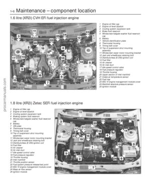 7
7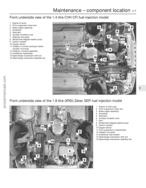 8
8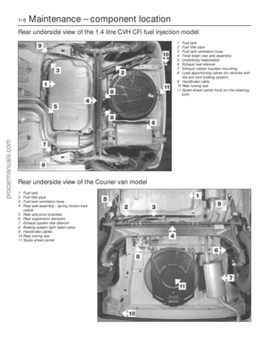 9
9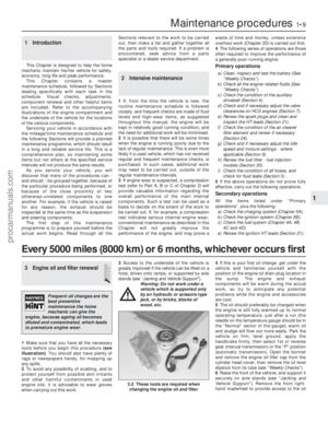 10
10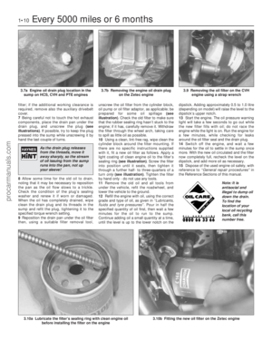 11
11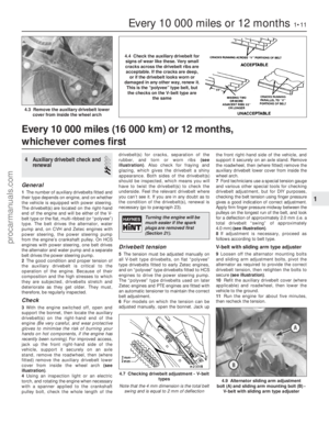 12
12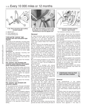 13
13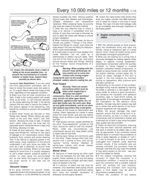 14
14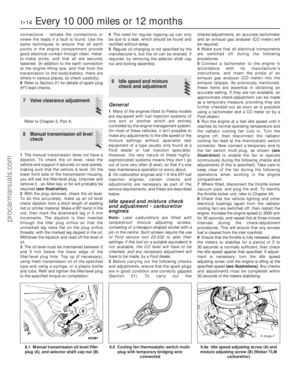 15
15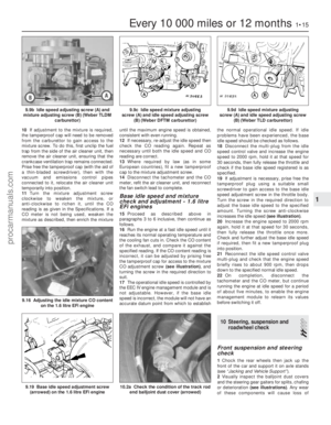 16
16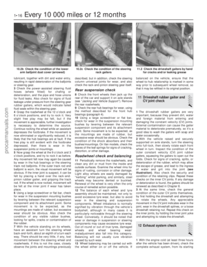 17
17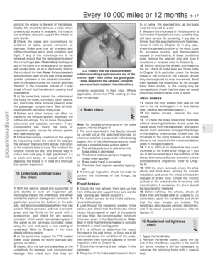 18
18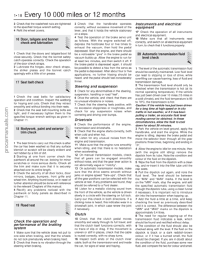 19
19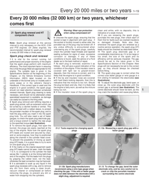 20
20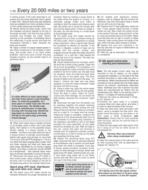 21
21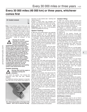 22
22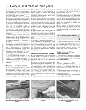 23
23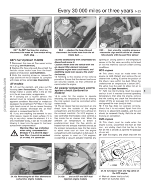 24
24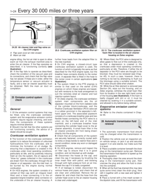 25
25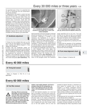 26
26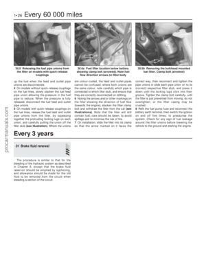 27
27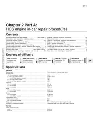 28
28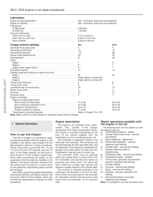 29
29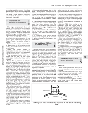 30
30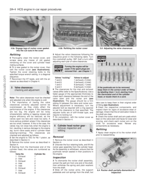 31
31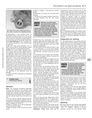 32
32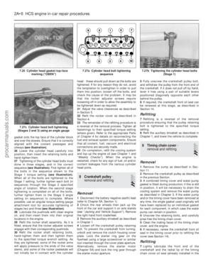 33
33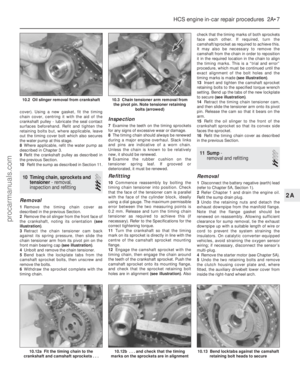 34
34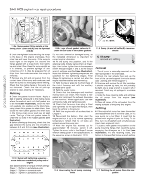 35
35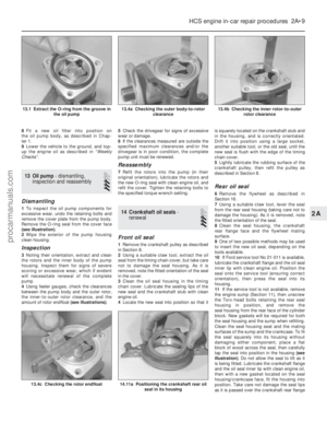 36
36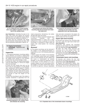 37
37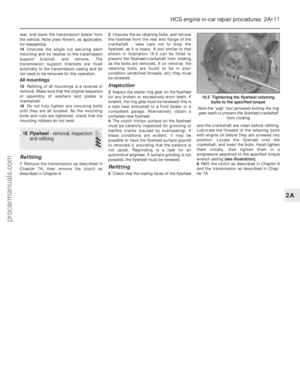 38
38 39
39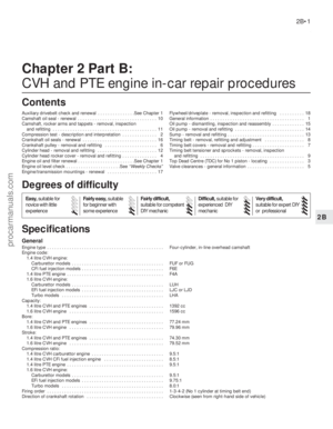 40
40 41
41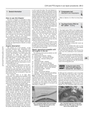 42
42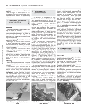 43
43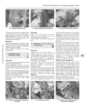 44
44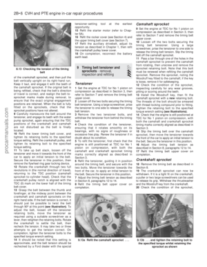 45
45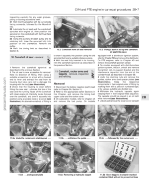 46
46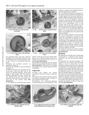 47
47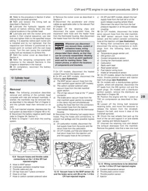 48
48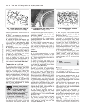 49
49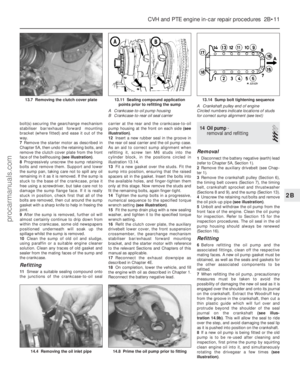 50
50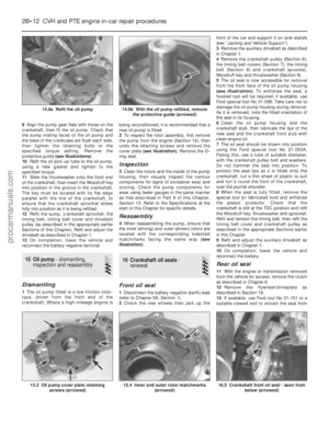 51
51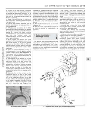 52
52 53
53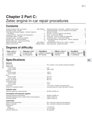 54
54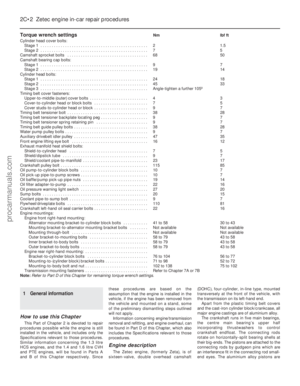 55
55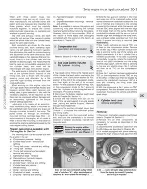 56
56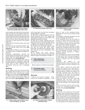 57
57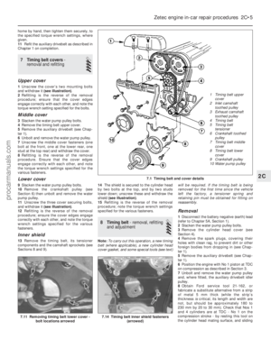 58
58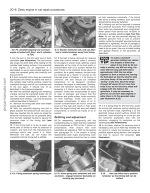 59
59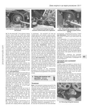 60
60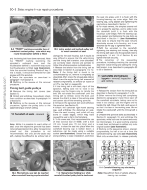 61
61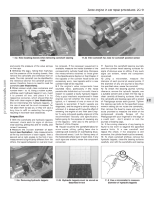 62
62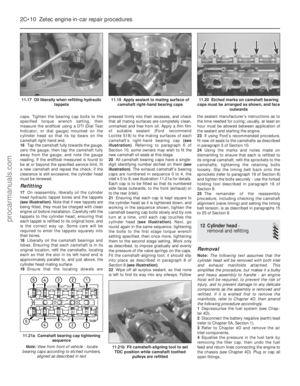 63
63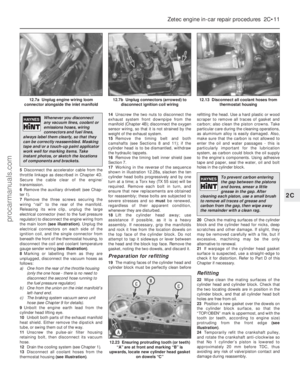 64
64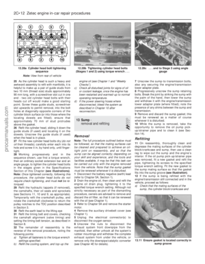 65
65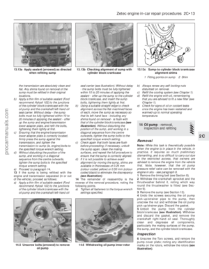 66
66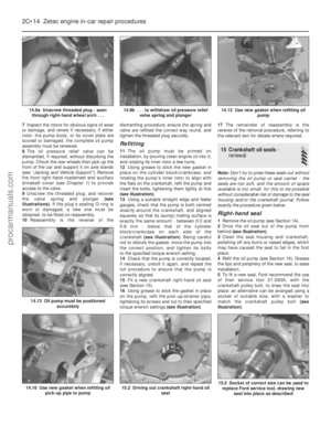 67
67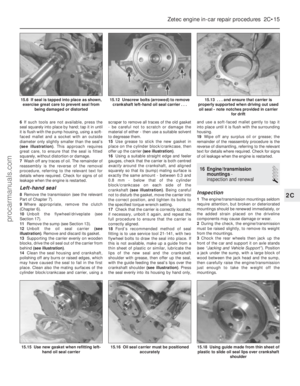 68
68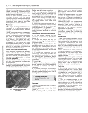 69
69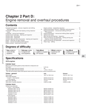 70
70 71
71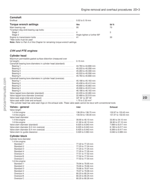 72
72 73
73 74
74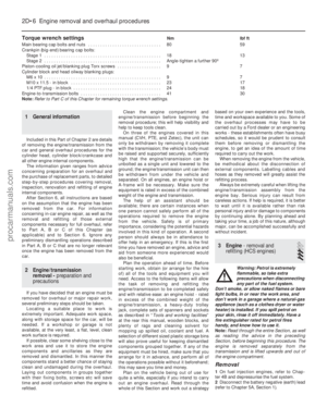 75
75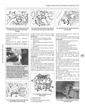 76
76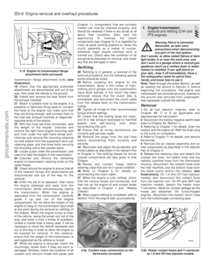 77
77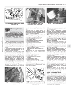 78
78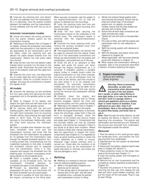 79
79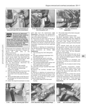 80
80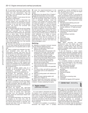 81
81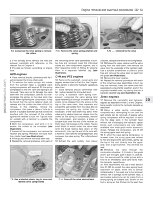 82
82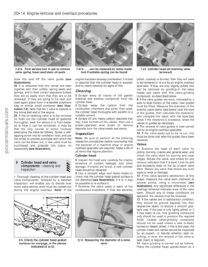 83
83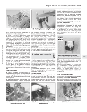 84
84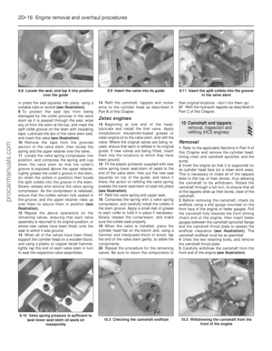 85
85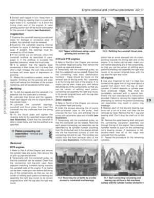 86
86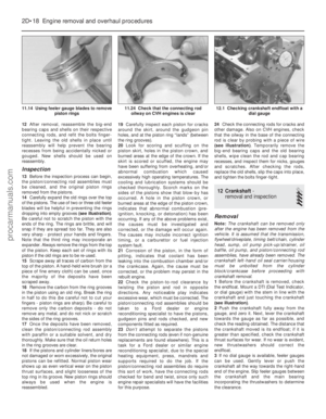 87
87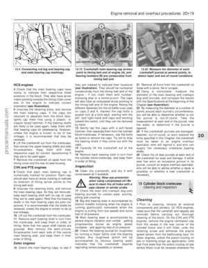 88
88 89
89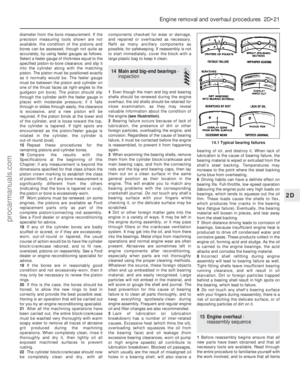 90
90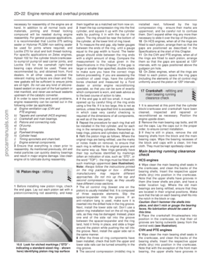 91
91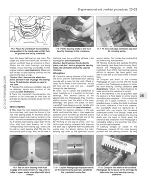 92
92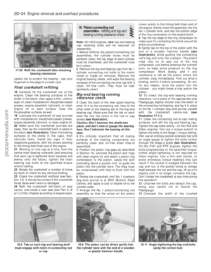 93
93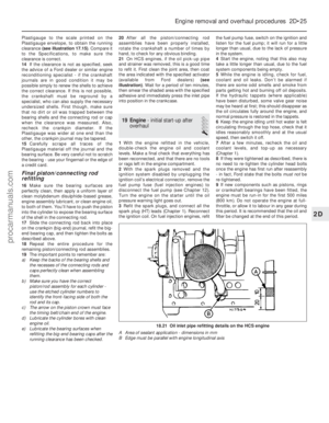 94
94 95
95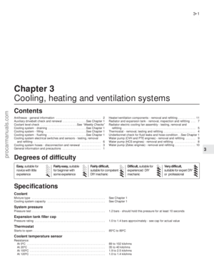 96
96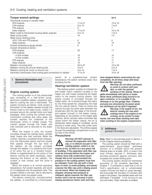 97
97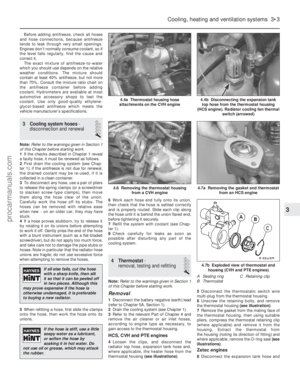 98
98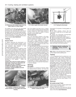 99
99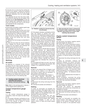 100
100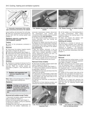 101
101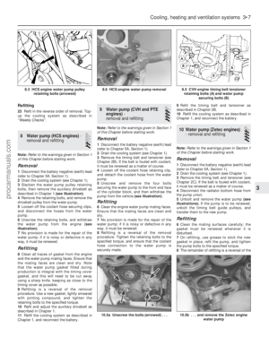 102
102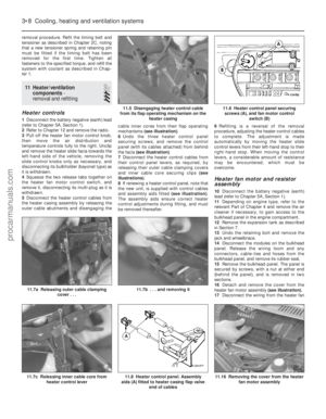 103
103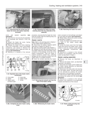 104
104 105
105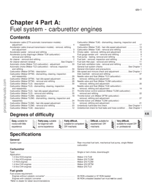 106
106 107
107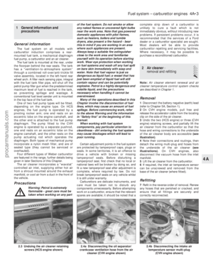 108
108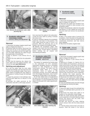 109
109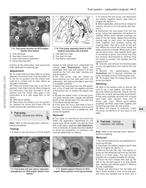 110
110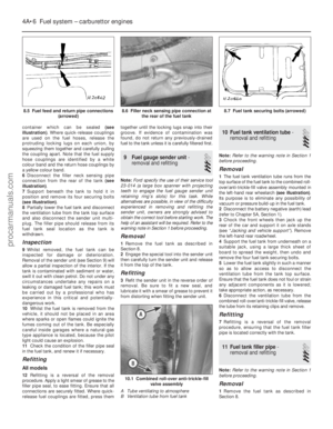 111
111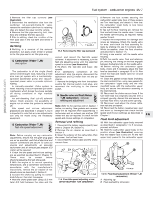 112
112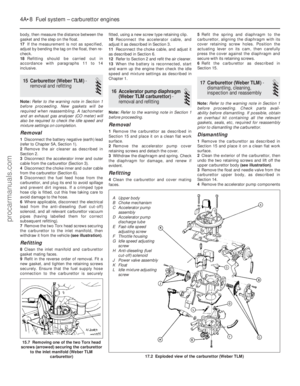 113
113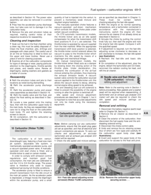 114
114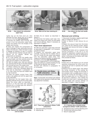 115
115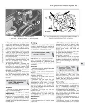 116
116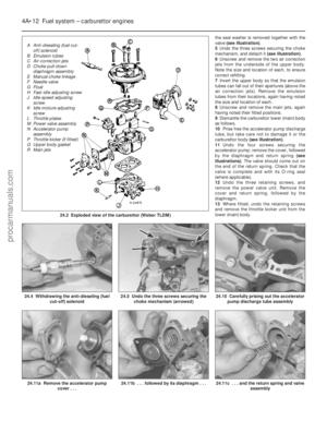 117
117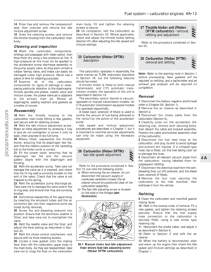 118
118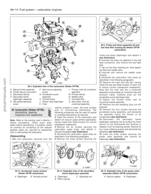 119
119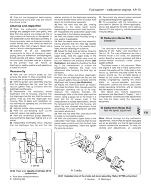 120
120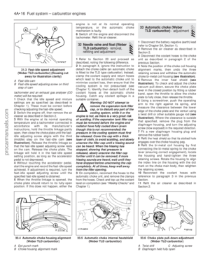 121
121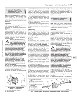 122
122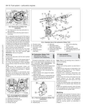 123
123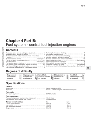 124
124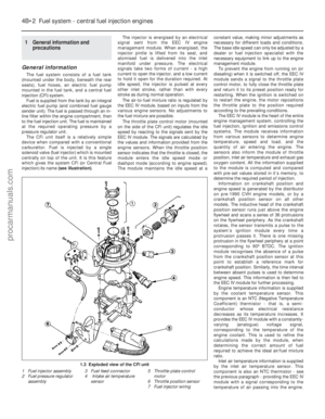 125
125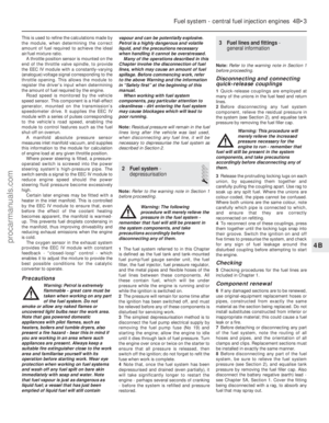 126
126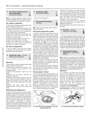 127
127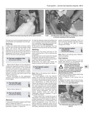 128
128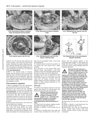 129
129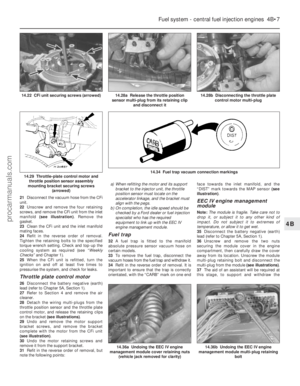 130
130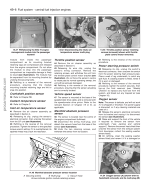 131
131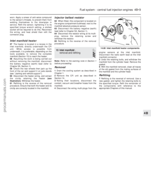 132
132 133
133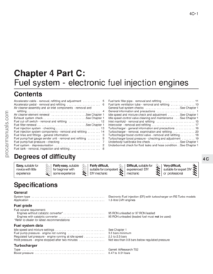 134
134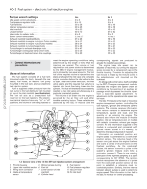 135
135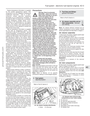 136
136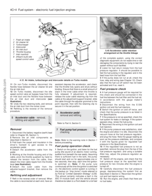 137
137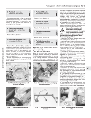 138
138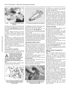 139
139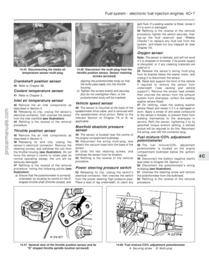 140
140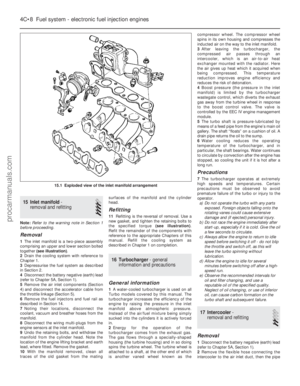 141
141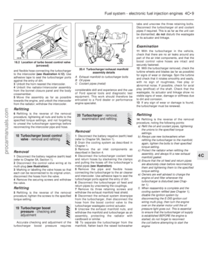 142
142 143
143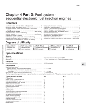 144
144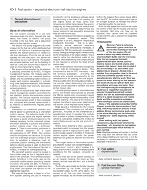 145
145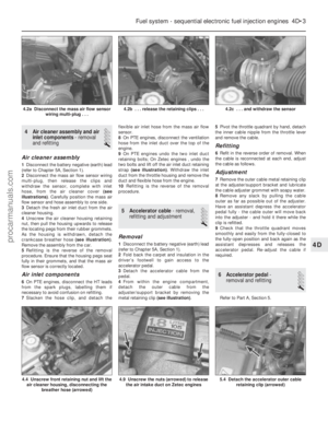 146
146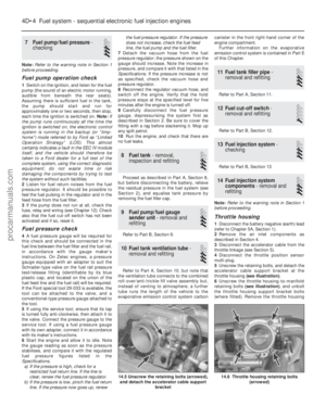 147
147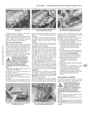 148
148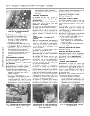 149
149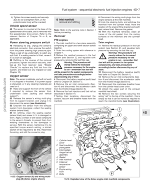 150
150 151
151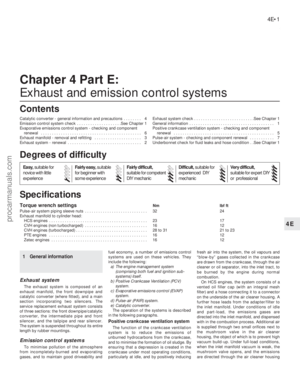 152
152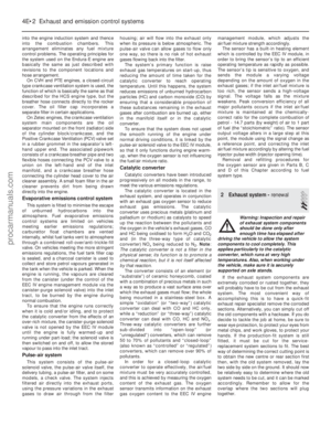 153
153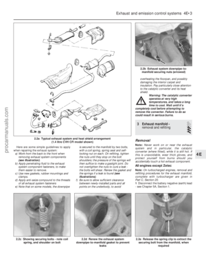 154
154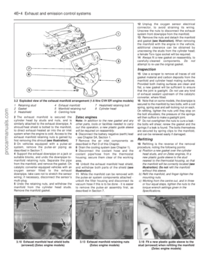 155
155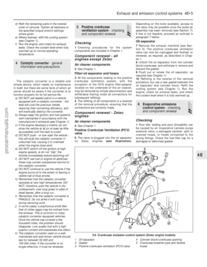 156
156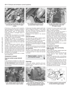 157
157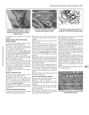 158
158 159
159 160
160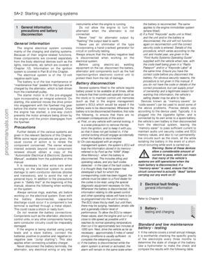 161
161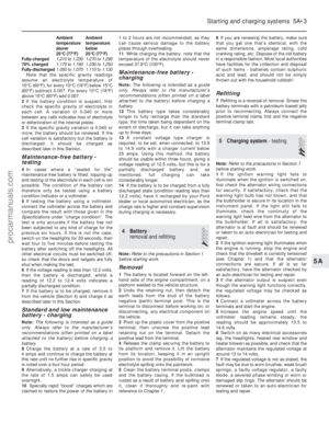 162
162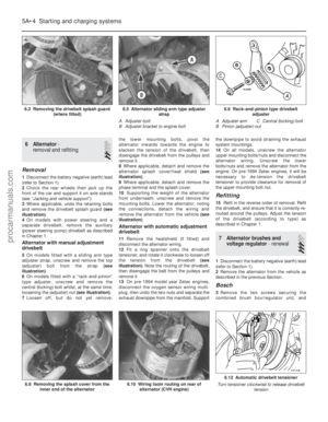 163
163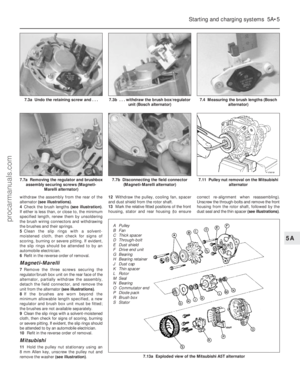 164
164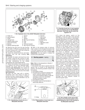 165
165 166
166 167
167 168
168 169
169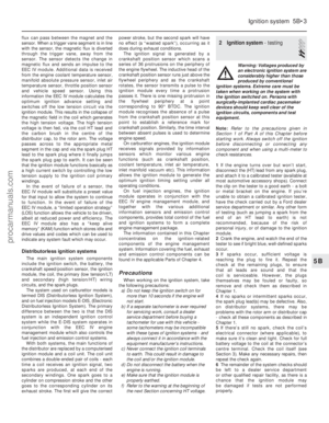 170
170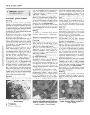 171
171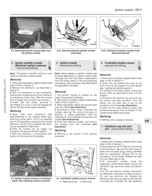 172
172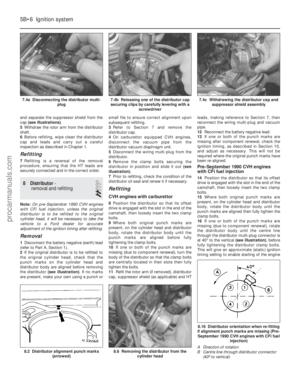 173
173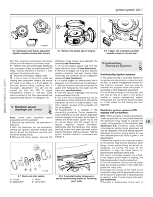 174
174 175
175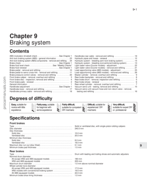 176
176 177
177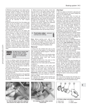 178
178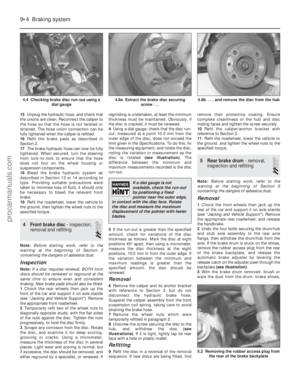 179
179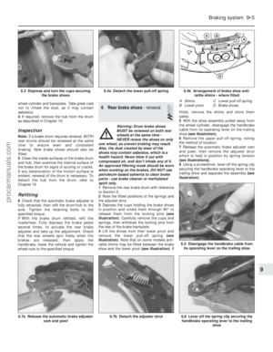 180
180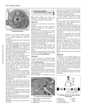 181
181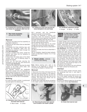 182
182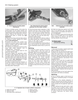 183
183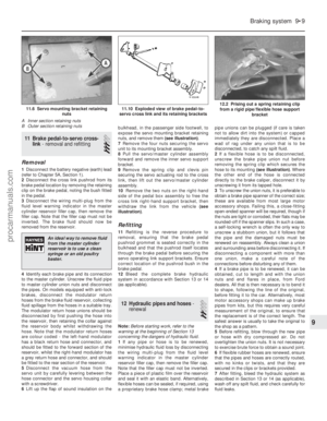 184
184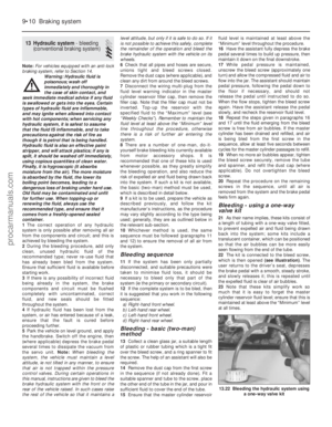 185
185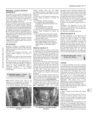 186
186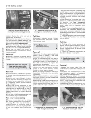 187
187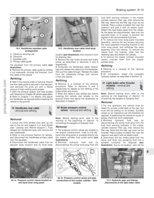 188
188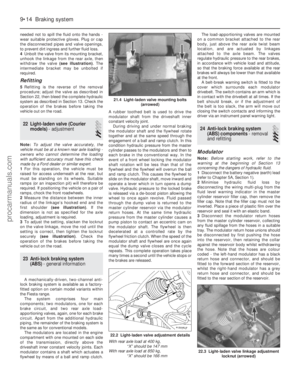 189
189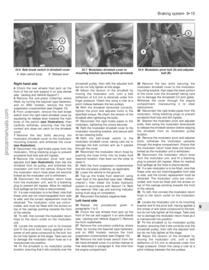 190
190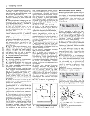 191
191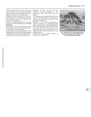 192
192 193
193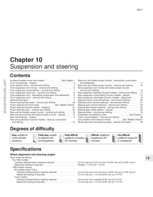 194
194 195
195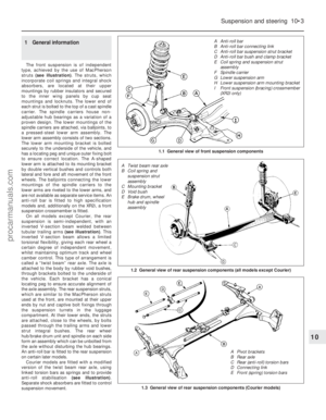 196
196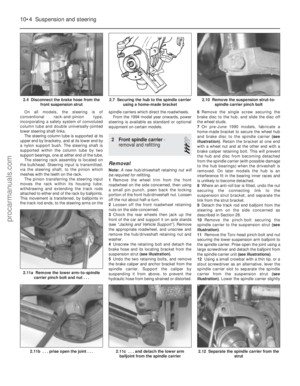 197
197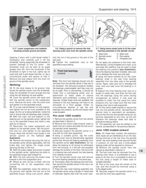 198
198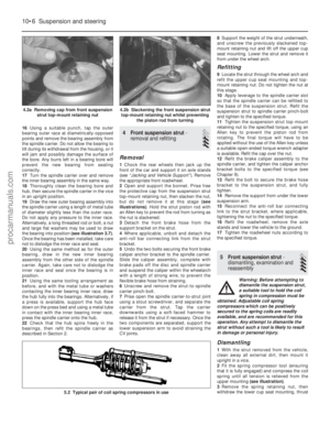 199
199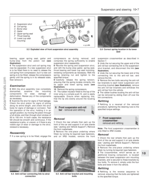 200
200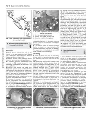 201
201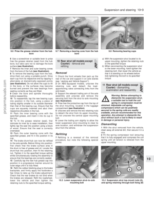 202
202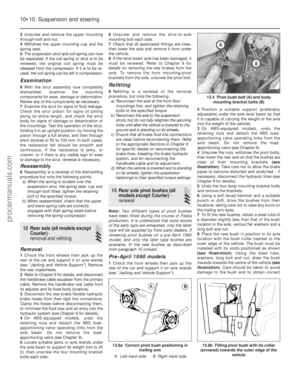 203
203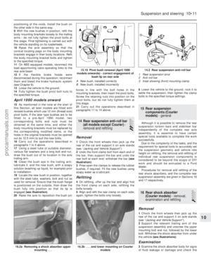 204
204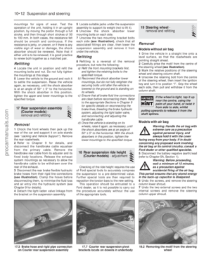 205
205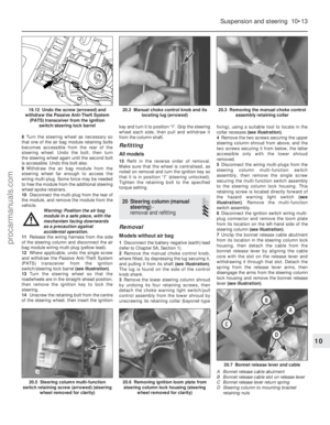 206
206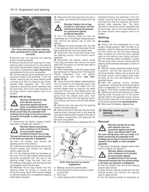 207
207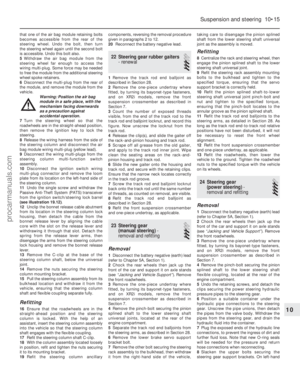 208
208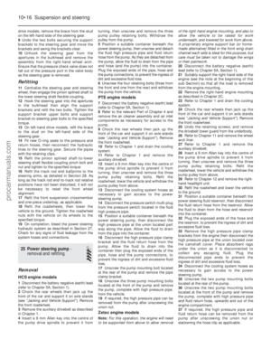 209
209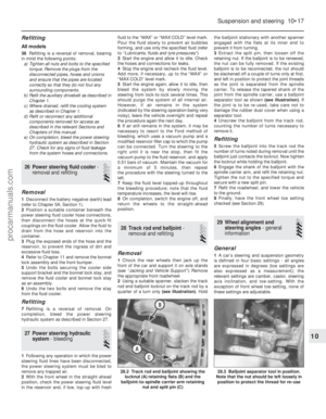 210
210 211
211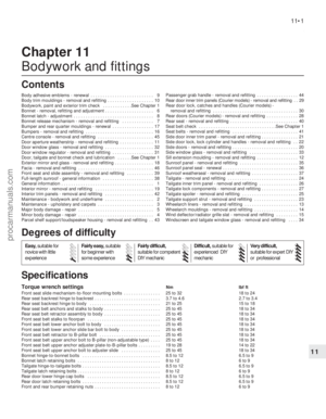 212
212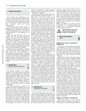 213
213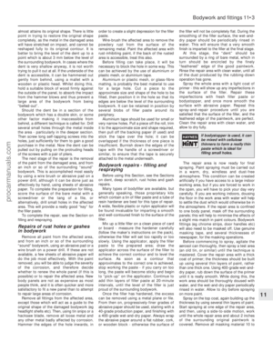 214
214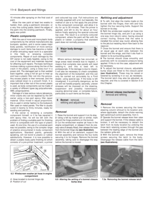 215
215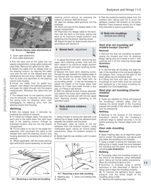 216
216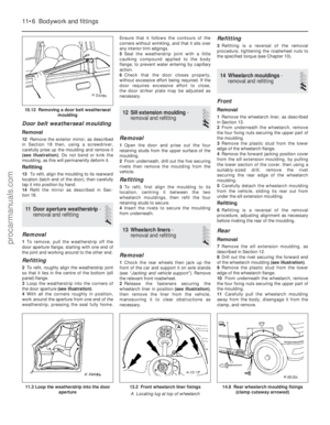 217
217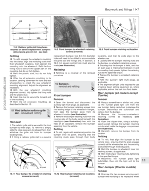 218
218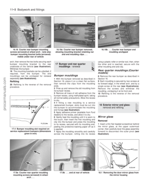 219
219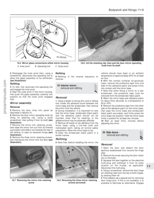 220
220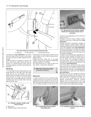 221
221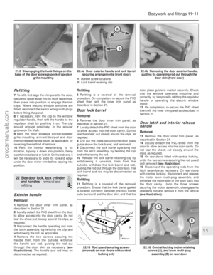 222
222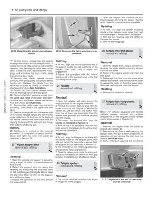 223
223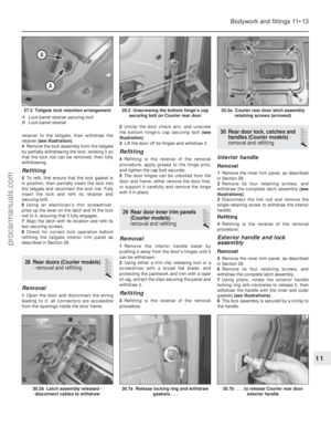 224
224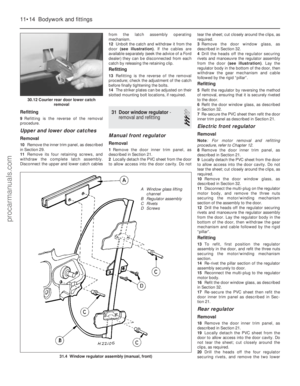 225
225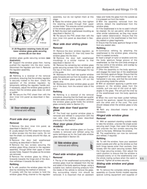 226
226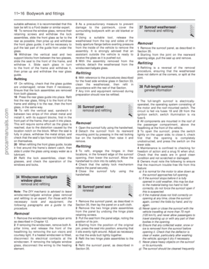 227
227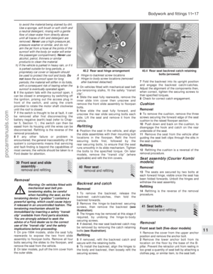 228
228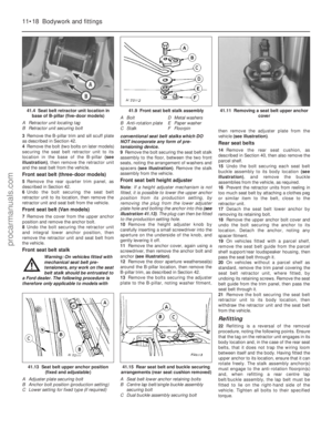 229
229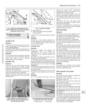 230
230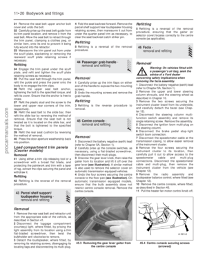 231
231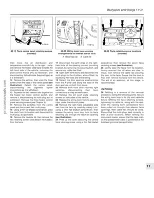 232
232 233
233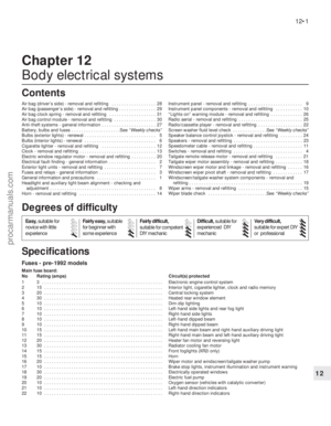 234
234 235
235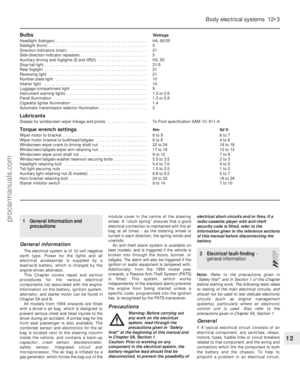 236
236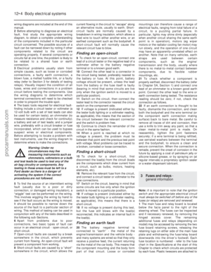 237
237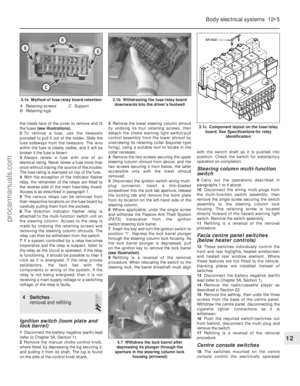 238
238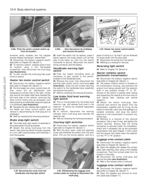 239
239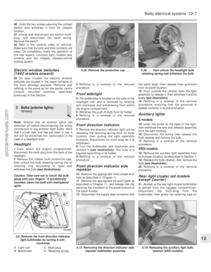 240
240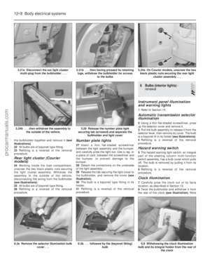 241
241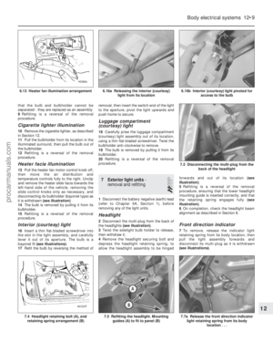 242
242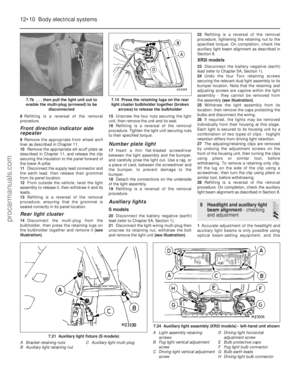 243
243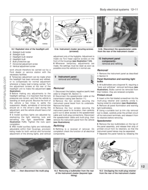 244
244 245
245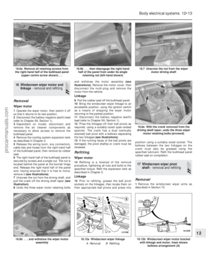 246
246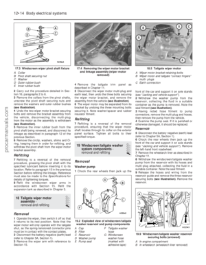 247
247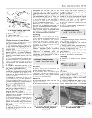 248
248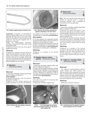 249
249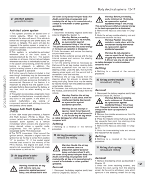 250
250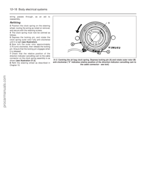 251
251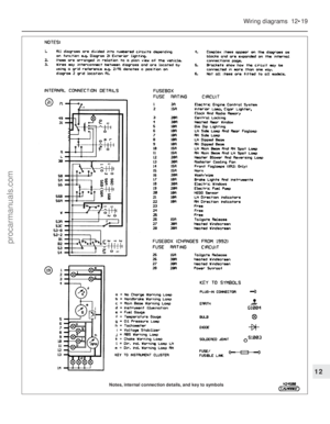 252
252 253
253 254
254 255
255 256
256 257
257 258
258 259
259 260
260 261
261 262
262 263
263 264
264 265
265 266
266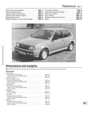 267
267 268
268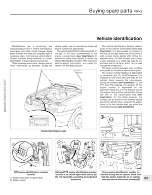 269
269 270
270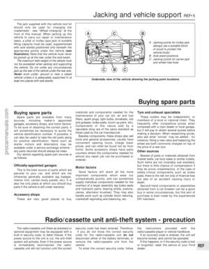 271
271 272
272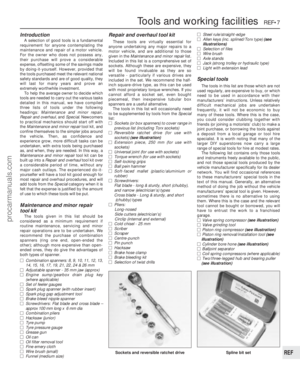 273
273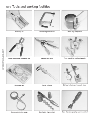 274
274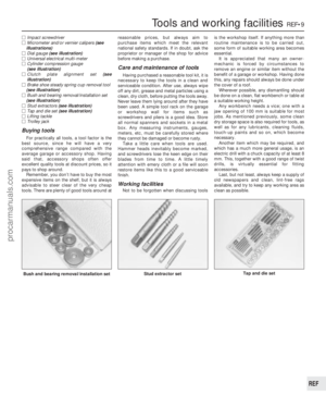 275
275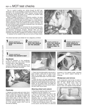 276
276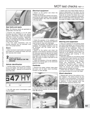 277
277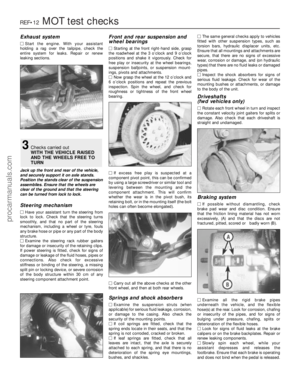 278
278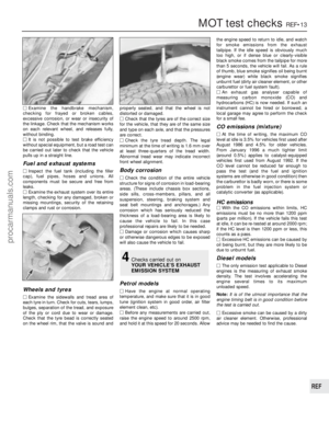 279
279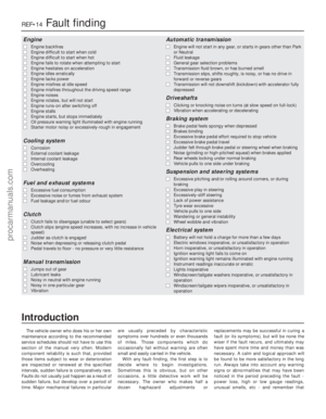 280
280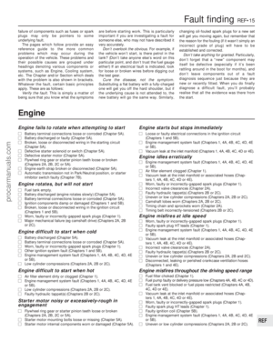 281
281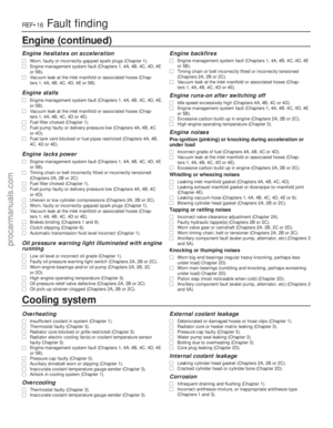 282
282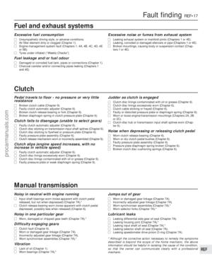 283
283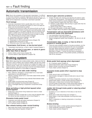 284
284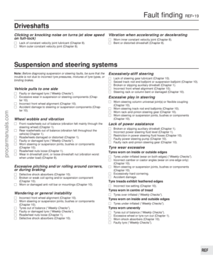 285
285 286
286 287
287 288
288 289
289 290
290 291
291 292
292 293
293 294
294 295
295