Page 209 of 296

drive models, remove the brace from the stud
on the left-hand side of the steering gear.
9Undo the two bolts securing the support
brackets to the steering gear and move the
brackets and swing the brackets clear.
10 Unhook the steering gear from the
apertures in the bulkhead and remove the
assembly from the right-hand wheel arch.
Ensure that the pressure check valve does not
fall out of the pressure port in the valve body
as the steering gear is removed.
Refitting
11 Centralize the steering gear and steering
wheel, then engage the pinion splined shaft to
the lower steering shaft flexible coupling.
12 Hook the steering gear into the apertures
in the bulkhead then align the support
brackets and refit the two bolts. Tighten the
support bracket upper bolts and support
bracket-to-steering gear bolts to the specified
torque.
13 On left-hand drive models, refit the brace
to the stud on the left-hand side of the
steering gear.
14 Fit new O-ring seals to the pressure and
return hoses, then reconnect the hydraulic
lines to the steering gear. Secure the pipes
with the retaining clips.
15 Refit the pinion splined shaft-to-lower
steering shaft flexible coupling pinch-bolt and
nut and tighten to the specified torque.
16 Refit the track rod end balljoints to the
steering arms, as detailed in Section 28. As
long as the track rod end-to-track rod relative
positions have not been disturbed, it will not
be necessary to reset the front wheel
alignment.
17 Refit the front suspension crossmember
and one-piece undertray, as applicable.
18 Refit the roadwheels, then lower the
vehicle to the ground. Tighten the roadwheel
nuts with the vehicle on its wheels to the
specified torque.
19 On completion, bleed the power steering
hydraulic system as described in Section 27.
Check for any signs of fluid leakage from the
system hoses and connections.
25 Power steering pump -
removal and refitting
4
Removal
HCS engine models
1 Disconnect the battery negative (earth) lead
(refer to Chapter 5A, Section 1).
2 Chock the rear wheels then jack up the
front of the car and support it on axle stands
(see “Jacking and Vehicle Support” ). Remove
the front roadwheel.
3 Remove the auxiliary drivebelt as described
in Chapter 1.
4 Insert a 9 mm Allen key into the centre of
the pump drive spindle to prevent it from turning, then unscrew and remove the three
pump pulley retaining bolts. Withdraw the
pulley from the pump.
5
Position a suitable container beneath the
power steering pump, then unscrew and detach
the fluid high pressure pipe and fluid return
hose from the pump. As they are detached from
the pump, allow the fluid to drain from the pipe
and hose (and the pump) into the container.
Plug the exposed ends of the pipe, hose and
the pump connections, to prevent the ingress of
dirt and excessive fluid loss.
6 Unscrew the four retaining bolts (three from
the front and one from the rear) and withdraw
the pump from the vehicle.
PTE engine models
7 Disconnect the battery negative (earth) lead
(refer to Chapter 5A, Section 1).
8 Refer to the relevant Part of Chapter 4 and
remove the air cleaner assembly and air inlet
components as necessary for access to the
pump.
9 Chock the rear wheels then jack up the
front of the car and support it on axle stands
(see “Jacking and Vehicle Support” ). Remove
the front roadwheel.
10 Refer to Chapter 1 and drain the cooling
system.
11 Refer to Chapter 1 and remove the
auxiliary drivebelt.
12 Insert a 9 mm Allen key into the centre of
the pump drive spindle to prevent it from
turning, then unscrew and remove the three
pump pulley retaining bolts. Refit the
roadwheel, lower the vehicle and withdraw the
pump pulley from above.
13 Disconnect the cooling system hoses as
necessary to gain access to the power
steering pump.
14 Disconnect the pressure switch multi-plug
from the pressure switch located in the fluid
high pressure pipe.
15 Position a suitable container beneath the
power steering pump, then disconnect the
high pressure pipe at the union located part
way along the pipe. Allow the fluid to drain
from the pipe into the container.
16 Disconnect the high pressure pipe clamp
bracket and the fluid return hose from the
pump. Allow the fluid to drain into the
container then plug the exposed ends of the
pipe, hose and the pump connections, to
prevent the ingress of dirt and excessive fluid
loss.
17 Unscrew the pump mounting bolt located
at the rear of the pump and remove the pipe
clamp bracket.
18 Unscrew the three pump mounting bolts
located at the front of the pump and remove
the pump, complete with high pressure pipe,
from the vehicle.
19 If required, the high pressure pipe can be
removed from the pump after unscrewing the
union nut.
Zetec engine models
Note: For this operation, the engine will need
to be supported from above to allow removal of the right-hand engine mounting, and also to
allow the vehicle to be raised for work
underneath, and lowered for work from above.
A proprietary engine support bar (or home-
made alternative) fitted in the front wing drain
channel each side is ideal for this purpose, but
care must be taken not to damage the wings
or their paintwork.
20
Disconnect the battery negative (earth)
lead (refer to Chapter 5A, Section 1).
21 Suitably support the right-hand side of the
engine (see the note at the beginning of this
sub-Section) so that all the load is removed
from the engine mounting.
22 Remove the right-hand engine mounting
as described in Chapter 2C.
23 Refer to Chapter 1 and drain the cooling
system.
24 Chock the rear wheels then jack up the
front of the car and support it on axle stands
(see “Jacking and Vehicle Support” ). Remove
the front roadwheel.
25 Undo the retaining screws, and remove
the drivebelt lower guard from the underbody.
26 Refer to Chapter 11 and remove the wheel
arch liner.
27 Refer to Chapter 1 and remove the
auxiliary drivebelt.
28 Insert a 9 mm Allen key into the centre of
the pump drive spindle to prevent it from
turning, then unscrew and remove the three
pump pulley retaining bolts. Refit the
roadwheel, lower the vehicle and withdraw the
pump pulley from above.
29 Refer to Chapter 12 and remove the right-
hand headlight unit.
30 Refit the roadwheel and lower the vehicle
to the ground.
31 Position a suitable container beneath the
power steering fluid reservoir, then disconnect
the fluid return hose from the reservoir. Allow
the fluid to drain from the hose and reservoir
into the container.
32 Plug the exposed ends of the hose and
the reservoir, to prevent the ingress of dirt and
excessive fluid loss.
33 Remove the high pressure pipe clamp
brackets from the engine then disconnect the
high pressure pipe at the union located over
the camshaft cover. Place absorbent rags
under the union as it is disconnected to
collect any escaping fluid. Plug the
disconnected pipe ends to prevent the
ingress of dirt and excessive fluid loss.
34 Disconnect the cooling system hoses as
necessary to gain access to the power
steering pump.
35 Unscrew the two pump mounting bolts
located at the rear of the pump.
36 Unscrew the two pump mounting bolts
located at the front of the pump and remove
the pump, complete with high pressure pipe
and fluid return hose, upwards and out of the
engine compartment.
37 If required, the high pressure pipe and
fluid return hose can be removed from the
pump after unscrewing the union nut or
slackening the hose clip as applicable.
10•16 Suspension and steering
1595Ford Fiesta Remakeprocarmanuals.com
http://vnx.su
Page 210 of 296
 Tighten all nuts and bolts to the specified torque. Remove the plugs from the
disconnected pipes, ho")
Refitting
All models
38Refitting is a reversal of removal, bearing
in mind the following points:
a) Tighten all nuts and bolts to the specified torque. Remove the plugs from the
disconnected pipes, hoses and unions
and ensure that the pipes are located
correctly so that they do not foul any
surrounding components.
b) Refit the auxiliary drivebelt as described in
Chapter 1.
c) Where drained, refill the cooling system as described in Chapter 1.
d) Refit or reconnect any additional
components removed for access as
described in the relevant Sections and
Chapters of this manual.
e) On completion, bleed the power steering
hydraulic system as described in Section
27. Check for any signs of fluid leakage
from the system hoses and connections.
26 Power steering fluid cooler -
removal and refitting
2
Removal
1 Disconnect the battery negative (earth) lead
(refer to Chapter 5A, Section 1).
2 Position a suitable container beneath the
power steering fluid cooler hose connections,
then disconnect the hoses at the quick-fit
couplings on the fluid cooler. Allow the fluid to
drain from the hose and reservoir into the
container.
3 Plug the exposed ends of the hose and the
reservoir, to prevent the ingress of dirt and
excessive fluid loss.
4 Refer to Chapter 11 and remove the bonnet
lock assembly and the front bumper.
5 Undo the bolts securing the cooler side
support bracket and the bonnet lock stay, and
remove the fluid cooler and bonnet lock stay
as an assembly.
6 Undo the two bolts and remove the stay
from the fluid cooler.
Refitting
7 Refitting is a reversal of removal. On
completion, bleed the power steering
hydraulic system as described in Section 27.
27 Power steering hydraulic system - bleeding
2
1Following any operation in which the power
steering fluid lines have been disconnected,
the power steering system must be bled to
remove any trapped air.
2 With the front wheel in the straight-ahead
position, check the power steering fluid level
in the reservoir and, if low, top-up with fresh fluid to the “MAX” or “MAX COLD” level mark.
Pour the fluid slowly to prevent air bubbles
forming, and use only the specified fluid (refer
to
“Lubricants, fluids and tyre pressures” ).
3 Start the engine and allow it to idle. Check
the hoses and connections for leaks.
4 Stop the engine and recheck the fluid level.
Add more, if necessary, up to the “MAX” or
“MAX COLD” level mark.
5 Start the engine again, allow it to idle, then
bleed the system by slowly moving the
steering from lock-to-lock several times. This
should purge the system of all internal air.
However, if air remains in the system
(indicated by the steering operation being very
noisy), leave the vehicle overnight and repeat
the procedure again the next day.
6 If air still remains in the system, it may be
necessary to resort to the Ford method of
bleeding, which uses a vacuum pump and a
modified reservoir filler cap to which the pump
can be connected. Turn the steering to the
right until it is near the stop, then fit the
vacuum pump to the fluid reservoir, and apply
0.51 bars of vacuum. Maintain the vacuum for
a minimum of 5 minutes, then repeat
the procedure with the steering turned to the
left.
7 Keep the fluid level topped-up throughout
the bleeding procedure; note that the fluid
temperature increases, the level will rise.
8 On completion, switch the engine off, and
return the wheels to the straight-ahead
position.
28 Track rod end balljoint -
removal and refitting
2
Removal
1 Chock the rear wheels then jack up the
front of the car and support it on axle stands
(see “Jacking and Vehicle Support” ). Remove
the appropriate front roadwheel.
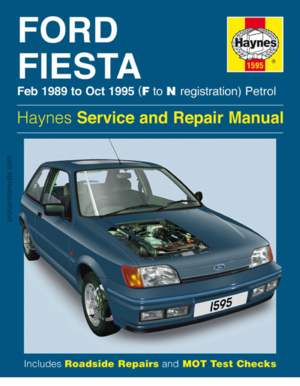
2 Using a suitable spanner, slacken the track
rod end balljoint locknut on the track rod by a
quarter of a turn only (see illustration). Holdthe balljoint stationary with another spanner
engaged with the flats at its inner end to
prevent it from turning.
3
Extract the split pin, then loosen off the
retaining nut. If the balljoint is to be renewed,
the nut can be fully removed. If the existing
balljoint is to be reconnected, the nut should
be slackened off a couple of turns only at first,
and left in position to protect the joint threads
as the joint is separated from the spindle
carrier. To release the tapered shank of the
joint from the spindle carrier, use a balljoint
separator tool as shown (see illustration). If
the joint is to be re-used, take care not to
damage the rubber dust cover when using a
separator tool.
4 Unscrew the balljoint from the track rod,
counting the number of turns necessary to
remove it.
Refitting
5 Screw the balljoint into the track rod the
number of turns noted during removal until the
balljoint just contacts the locknut. Now tighten
the locknut while holding the balljoint.
6 Engage the shank of the balljoint with the
spindle carrier arm, and refit the retaining nut.
Tighten the nut to the specified torque and
secure with a new split pin.
7 Refit the roadwheel, and lower the vehicle
to the ground.
8 Finally, have the front wheel toe setting
checked (see Section 29).
29 Wheel alignment and steering angles - general
information
4
General
1 A car’s steering and suspension geometry
is defined in four basic settings - all angles
are expressed in degrees (toe settings are
also expressed as a measurement); the
relevant settings are camber, castor, steering
axis inclination, and toe-setting. With the
exception of front wheel toe-setting, none of
these settings are adjustable.
Suspension and steering 10•17
28.3 Balljoint separator tool in position.
Note that the nut should be left loosely in position to protect the thread for re-use28.2 Track rod end balljoint showing the locknut (A) retaining flats (B) and the
balljoint-to-spindle carrier arm retaining
nut and split pin (C)
10
1595Ford Fiesta Remakeprocarmanuals.com
http://vnx.su
Page 211 of 296

Front wheel toe setting -
checking and adjustment
2Due to the special measuring equipment
necessary to accurately check the wheel
alignment, and the skill required to use it
properly, checking and adjustment is best left
to a Ford dealer or similar expert. Note that
most tyre-fitting shops now possess
sophisticated checking equipment. The
following is provided as a guide, should the
owner decide to carry out a DIY check.
3 The front wheel toe setting is checked by
measuring the distance between the front and
rear inside edges of the roadwheel rims.
Proprietary toe measurement gauges are
available from motor accessory shops.
Adjustment is made by screwing the track
rods in or out of their track rod end balljoints,
to alter the effective length of the track rod
assemblies.
4 For accurate checking, the vehicle must
be at the kerb weight, ie unladen and with a
full tank of fuel.
5 Before starting work, check the tyre
pressures and tread wear, the condition of the
hub bearings, the steering wheel free play,
and the condition of the front suspension
components (see Chapter 1). Correct any
faults found.
6 Park the vehicle on level ground, check that
the front roadwheels are in the straight-ahead
position, then rock the rear and front ends to settle the suspension. Release the handbrake,
and roll the vehicle backwards 1 metre, then
forwards again, to relieve any stresses in the
steering and suspension components.
7
Measure the distance between the front
edges of the wheel rims and the rear edges of
the rims. Subtract the smallest measurement
from the largest, and check that the result is
within the specified range.
8 If adjustment is necessary, apply the
handbrake, then jack up the front of the
vehicle and support it securely on axle stands
(see “Jacking and Vehicle Support” ). Turn the
steering wheel onto full-left lock, and record
the number of exposed threads on the right-
hand track rod. Now turn the steering onto
full-right lock, and record the number of
threads on the left-hand side. If there are the
same number of threads visible on both sides,
then subsequent adjustment should be made
equally on both sides. If there are more
threads visible on one side than the other, it
will be necessary to compensate for this
during adjustment. Note:It is most important
that after adjustment, the same number of
threads are visible on each track rod.
9 First clean the track rod end; if they are
corroded, apply penetrating fluid before
starting adjustment. Release the rubber gaiter
outboard clips (where necessary), and peel
back the gaiter; apply a smear of grease to
the inside of the gaiter, so that both are free, and will not be twisted or strained as their
respective track rods are rotated.
10
Use a straight-edge and a scriber or
similar to mark the relationship of each track
rod to its track rod end balljoint, then, holding
each track rod in turn, unscrew its locknut
fully.
11 Alter the length of the track rods, bearing
in mind the note made in paragraph 8. Screw
them into or out of the track rod end balljoints,
rotating the track rods using a self-grip
wrench. Shortening the track rods (screwing
them into their track rod end balljoints) will
reduce toe-in/increase toe-out.
12 When the setting is correct, hold the track
rods and securely tighten the track rod end
balljoint locknuts. Count the exposed threads
to check the length of both track rods. If they
are not the same, then the adjustment has not
been made equally, and problems will be
encountered with tyre scrubbing in turns;
also, the steering wheel spokes will no longer
be horizontal when the wheels are in the
straight-ahead position.
13 If the track rod lengths are the same, lower
the vehicle to the ground and re-check the
toe setting; re-adjust if necessary. When the
setting is correct, securely tighten the track rod
end balljoint locknuts. Ensure that the rubber
gaiters are seated correctly, and are not
twisted or strained, and secure them in position
with new retaining clips (where necessary).
10•18 Suspension and steering
1595Ford Fiesta Remakeprocarmanuals.com
http://vnx.su
Page 212 of 296

11
1595Ford Fiesta Remake
Torque wrench settingsNmlbf ft
Front seat slide mechanism-to-floor mounting bolts . . . . . . . . . . . . . . . 25 to 32 18 to 24
Rear seat backrest hinge to backrest . . . . . . . . . . . . . . . . . . . . . . . . . . . 3.7 to 4.6 2.7 to 3.4
Rear seat backrest hinge to body . . . . . . . . . . . . . . . . . . . . . . . . . . . . . 21 to 25 15 to 18
Rear seat belt anchors and stalks to body . . . . . . . . . . . . . . . . . . . . . . . 25 to 45 18 to 34
Rear seat belt retractor assembly to body . . . . . . . . . . . . . . . . . . . . . . . 25 to 45 18 to 34
Front seat belt stalks to floorpan . . . . . . . . . . . . . . . . . . . . . . . . . . . . . . 25 to 45 18 to 34
Front seat belt lower anchor bolt to body . . . . . . . . . . . . . . . . . . . . . . . 25 to 45 18 to 34
Front seat belt lower anchor slide bar bolt to body . . . . . . . . . . . . . . . . 25 to 45 18 to 34
Front seat belt retractor to B-pillar bolt . . . . . . . . . . . . . . . . . . . . . . . . . 25 to 45 18 to 34
Front seat belt upper anchor bolt to B-pillar (non-adjustable type) . . . . 25 to 45 18 to 34
Front seat belt upper anchor adjuster plate-to-B-pillar bolts . . . . . . . . . 19 to 28 14 to 22
Front seat belt upper anchor bolt to adjuster slide . . . . . . . . . . . . . . . . 25 to 45 18 to 34
Bonnet hinge-to-bonnet bolts . . . . . . . . . . . . . . . . . . . . . . . . . . . . . . . . 8.5 to 12 6.5 to 9
Bonnet latch retaining bolts . . . . . . . . . . . . . . . . . . . . . . . . . . . . . . . . . . 8 to 12 6 to 9
Tailgate hinge-to-tailgate bolts . . . . . . . . . . . . . . . . . . . . . . . . . . . . . . . . 8.5 to 12 6.5 to 9
Tailgate latch retaining bolts . . . . . . . . . . . . . . . . . . . . . . . . . . . . . . . . . . 8 to 12 6 to 9
Rear door lower hinge cap bolts . . . . . . . . . . . . . . . . . . . . . . . . . . . . . . 8.5 to 12 6.5 to 9
Rear door latch retaining bolts . . . . . . . . . . . . . . . . . . . . . . . . . . . . . . . . 8.5 to 12 6.5 to 9
Front and rear bumper retaining nuts . . . . . . . . . . . . . . . . . . . . . . . . . . . 8 to 12 6 to 9
Chapter 11
Bodywork and fittings
Body adhesive emblems - renewal . . . . . . . . . . . . . . . . . . . . . . . . . . 9
Body trim mouldings - removal and refitting . . . . . . . . . . . . . . . . . . . 10
Bodywork, paint and exterior trim check . . . . . . . . . . . .See Chapter 1
Bonnet - removal, refitting and adjustment . . . . . . . . . . . . . . . . . . . . 6
Bonnet latch - adjustment . . . . . . . . . . . . . . . . . . . . . . . . . . . . . . . . . 8
Bonnet release mechanism - removal and refitting . . . . . . . . . . . . . 7
Bumper and rear quarter mouldings - renewal . . . . . . . . . . . . . . . . . 17
Bumpers - removal and refitting . . . . . . . . . . . . . . . . . . . . . . . . . . . . 16
Centre console - removal and refitting . . . . . . . . . . . . . . . . . . . . . . . 45
Door aperture weatherstrip - removal and refitting . . . . . . . . . . . . . . 11
Door window glass - removal and refitting . . . . . . . . . . . . . . . . . . . . 32
Door window regulator - removal and refitting . . . . . . . . . . . . . . . . . 31
Door, tailgate and bonnet check and lubrication . . . . . .See Chapter 1
Exterior mirror and glass - removal and refitting . . . . . . . . . . . . . . . . 18
Facia - removal and refitting . . . . . . . . . . . . . . . . . . . . . . . . . . . . . . . 46
Front seat and slide assembly - removal and refitting . . . . . . . . . . . 39
Full-length sunroof - general information . . . . . . . . . . . . . . . . . . . . . 38
General information . . . . . . . . . . . . . . . . . . . . . . . . . . . . . . . . . . . .\
. . 1
Interior mirror - removal and refitting . . . . . . . . . . . . . . . . . . . . . . . . 19
Interior trim panels - removal and refitting . . . . . . . . . . . . . . . . . . . . 42
Maintenance - bodywork and underframe . . . . . . . . . . . . . . . . . . . . 2
Maintenance - upholstery and carpets . . . . . . . . . . . . . . . . . . . . . . . 3
Major body damage - repair . . . . . . . . . . . . . . . . . . . . . . . . . . . . . . . 5
Minor body damage - repair . . . . . . . . . . . . . . . . . . . . . . . . . . . . . . . 4
Parcel shelf support/loudspeaker housing - removal and refitting . . 43 Passenger grab handle - removal and refitting . . . . . . . . . . . . . . . . . 44
Rear door inner trim panels (Courier models) - removal and refitting . . 29
Rear door lock, catches and handles (Courier models) -
removal and refitting . . . . . . . . . . . . . . . . . . . . . . . . . . . . . . . . . . . 30
Rear doors (Courier models) - removal and refitting . . . . . . . . . . . . . 28
Rear seat - removal and refitting . . . . . . . . . . . . . . . . . . . . . . . . . . . . 40
Seat belt check . . . . . . . . . . . . . . . . . . . . . . . . . . . . . . . .See Chap\
ter 1
Seat belts - removal and refitting . . . . . . . . . . . . . . . . . . . . . . . . . . . 41
Side door inner trim panel - removal and refitting . . . . . . . . . . .\
. . . . 21
Side door lock, lock cylinder and handles - removal and refitting . . 22
Side doors - removal and refitting . . . . . . . . . . . . . . . . . . . . . . . . . . . 20
Side window glass - removal and refitting . . . . . . . . . . . . . . . . . . . . 33
Sill extension moulding - removal and refitting . . . . . . . . . . . . . . . . . 12
Sunroof panel - removal and refitting . . . . . . . . . . . . . . . . . . . . . . . . 35
Sunroof panel seal - renewal . . . . . . . . . . . . . . . . . . . . . . . . . . . . . . . 36
Sunroof weatherseal - removal and refitting . . . . . . . . . . . . . . . . . . . 37
Tailgate - removal and refitting . . . . . . . . . . . . . . . . . . . . . . . . . . . . . 24
Tailgate inner trim panel - removal and refitting . . . . . . . . . . . . . . . . 26
Tailgate lock components - removal and refitting . . . . . . . . . . . . . . . 27
Tailgate spoiler - removal and refitting . . . . . . . . . . . . . . . . . . . . . . . 25
Tailgate support strut - removal and refitting . . . . . . . . . . . . . . . . . . 23
Wheelarch liners - removal and refitting . . . . . . . . . . . . . . . . . . . . . . 13
Wheelarch mouldings - removal and refitting . . . . . . . . . . . . . . . . . . 14
Wind deflector/radiator grille slat - removal and refitting . . . . . . . . . 15
Windscreen and tailgate window glass - removal and refitting . . . . 34
11•1
Specifications Contents
Easy, suitable for
novice with little
experience Fairly easy,
suitable
for beginner with
some experience Fairly difficult,
suitable for competent
DIY mechanic
Difficult,
suitable for
experienced DIY
mechanic Very difficult,
suitable for expert DIY
or professional
Degrees of difficulty
54321
procarmanuals.com
http://vnx.su
Page 213 of 296

1 General information
The bodyshell and underframe on all
models is of all-steel welded construction,
incorporating progressive crumple zones at
the front and rear, and a rigid centre safety
cell. The body styles available include three-
door, five-door, Van and Courier
configurations. A multi-stage anti-corrosion process is
applied to all new vehicles. This includes zinc
phosphating on some panels, the injection of
wax into boxed sections, and a wax and PVC
coating applied to the underbody for its
protection. Inertia reel seat belts are fitted to all
models, and from the 1994 model year
onwards, the front seat belt stalks are
mounted on automatic mechanical tensioners
(also known as “grabbers”). In the event of a
serious front impact, a spring mass sensor
releases a coil spring which pulls the stalk
buckle downwards and tensions the seat belt.
It is not possible to reset the tensioner once
fired, and it must therefore be renewed. Central locking is a standard or optional
fitment on all models. Where double-locking is
also fitted, the lock mechanism is
disconnected (when the system is in use) from
the interior door handles, making it impossible
to open any of the doors or the tailgate from
inside the vehicle. This means that, even if a
thief should break a side window, it will not be
possible to open the door using the interior
handle.
2 Maintenance -
bodywork and underframe
1
The general condition of a vehicle’s
bodywork is the one thing that significantly
affects its value. Maintenance is easy, but
needs to be regular. Neglect, particularly after
minor damage, can lead quickly to further
deterioration and costly repair bills. It is
important also to keep watch on those parts
of the vehicle not immediately visible, for
instance the underside, inside all the wheel
arches, and the lower part of the engine
compartment. The basic maintenance routine for the
bodywork is washing - preferably with a lot of
water, from a hose. This will remove all the
loose solids which may have stuck to the
vehicle. It is important to flush these off in
such a way as to prevent grit from scratching
the finish. The wheel arches and underframe
need washing in the same way, to remove any
accumulated mud, which will retain moisture
and tend to encourage rust. Oddly enough,
the best time to clean the underframe and
wheel arches is in wet weather, when the mud
is thoroughly wet and soft. In very wet weather, the underframe is usually cleaned of
large accumulations automatically, and this is
a good time for inspection.
Periodically, except on vehicles with a wax-
based underbody protective coating, it is a
good idea to have the whole of the
underframe of the vehicle steam-cleaned,
engine compartment included, so that a
thorough inspection can be carried out to see
what minor repairs and renovations are
necessary. Steam-cleaning is available at
many garages, and is necessary for the
removal of the accumulation of oily grime,
which sometimes is allowed to become thick
in certain areas. If steam-cleaning facilities are
not available, there are some excellent grease
solvents available which can be brush-
applied; the dirt can then be simply hosed off.
Note that these methods should not be used
on vehicles with wax-based underbody
protective coating, or the coating will be
removed. Such vehicles should be inspected
annually, preferably just prior to Winter, when
the underbody should be washed down, and
any damage to the wax coating repaired.
Ideally, a completely fresh coat should be
applied. It would also be worth considering
the use of such wax-based protection for
injection into door panels, sills, box sections,
etc, as an additional safeguard against rust
damage, where such protection is not
provided by the vehicle manufacturer. After washing paintwork, wipe off with a
chamois leather to give an unspotted clear
finish. A coat of clear protective wax polish
will give added protection against chemical
pollutants in the air. If the paintwork sheen
has dulled or oxidised, use a cleaner/polisher
combination to restore the brilliance of the
shine. This requires a little effort, but such
dulling is usually caused because regular
washing has been neglected. Care needs to
be taken with metallic paintwork, as special
non-abrasive cleaner/polisher is required to
avoid damage to the finish. Always check that
the door and ventilator opening drain holes
and pipes are completely clear, so that water
can be drained out .Brightwork should be
treated in the same way as paintwork.
Windscreens and windows can be kept clear
of the smeary film which often appears, by the
use of proprietary glass cleaner. Never use
any form of wax or other body or chromium
polish on glass.
3 Maintenance -
upholstery and carpets
1
Mats and carpets should be brushed or
vacuum-cleaned regularly, to keep them free
of grit. If they are badly stained, remove them
from the vehicle for scrubbing or sponging,
and make quite sure they are dry before
refitting. Seats and interior trim panels can be
kept clean by wiping with a damp cloth. If they
do become stained (which can be more apparent on light-coloured upholstery), use a
little liquid detergent and a soft nail brush to
scour the grime out of the grain of the
material. Do not forget to keep the headlining
clean in the same way as the upholstery.
When using liquid cleaners inside the vehicle,
do not over-wet the surfaces being cleaned.
Excessive damp could get into the seams and
padded interior, causing stains, offensive
odours or even rot.
Note
:
If the inside of the vehicle gets wet
accidentally, it is worthwhile taking some
trouble to dry it out properly, particularly
where carpets are involved .
Warning: Do not leave oil or
electric heaters inside the
vehicle for this purpose.
4 Minor body damage-
repair
3
Repairs of minor scratches in
bodywork
If the scratch is very superficial, and does
not penetrate to the metal of the bodywork,
repair is very simple. Lightly rub the area of
the scratch with a paintwork renovator, or a
very fine cutting paste, to remove loose paint
from the scratch, and to clear the surrounding
bodywork of wax polish. Rinse the area with
clean water. Apply touch-up paint to the scratch using a
fine paint brush; continue to apply fine layers
of paint until the surface of the paint in the
scratch is level with the surrounding
paintwork. Allow the new paint at least two
weeks to harden, then blend it into the
surrounding paintwork by rubbing the scratch
area with a paintwork renovator or a very fine
cutting paste. Finally, apply wax polish. Where the scratch has penetrated right
through to the metal of the bodywork, causing
the metal to rust, a different repair technique
is required. Remove any loose rust from the
bottom of the scratch with a penknife, then
apply rust-inhibiting paint to prevent the
formation of rust in the future. Using a rubber
or nylon applicator, fill the scratch with
bodystopper paste. If required, this paste can
be mixed with cellulose thinners to provide a
very thin paste which is ideal for filling narrow
scratches. Before the stopper-paste in the
scratch hardens, wrap a piece of smooth
cotton rag around the top of a finger. Dip the
finger in cellulose thinners, and quickly sweep
it across the surface of the stopper-paste in
the scratch; this will ensure that the surface
of the stopper-paste is slightly hollowed. The
scratch can now be painted over as described
earlier in this Section.
Repairs of dents in bodywork
When deep denting of the vehicle’s
bodywork has taken place, the first task is to
pull the dent out, until the affected bodywork
11•2 Bodywork and fittings
1595Ford Fiesta Remakeprocarmanuals.com
http://vnx.su
Page 214 of 296

almost attains its original shape. There is little
point in trying to restore the original shape
completely, as the metal in the damaged area
will have stretched on impact, and cannot be
reshaped fully to its original contour. It is
better to bring the level of the dent up to a
point which is about 3 mm below the level of
the surrounding bodywork. In cases where the
dent is very shallow anyway, it is not worth
trying to pull it out at all. If the underside of the
dent is accessible, it can be hammered out
gently from behind, using a mallet with a
wooden or plastic head. Whilst doing this,
hold a suitable block of wood firmly against
the outside of the panel, to absorb the impact
from the hammer blows and thus prevent a
large area of the bodywork from being
“belled-out”.Should the dent be in a section of the
bodywork which has a double skin, or some
other factor making it inaccessible from
behind, a different technique is called for. Drill
several small holes through the metal inside
the area - particularly in the deeper section.
Then screw long self-tapping screws into the
holes, just sufficiently for them to gain a good
purchase in the metal. Now the dent can be
pulled out by pulling on the protruding heads
of the screws with a pair of pliers. The next stage of the repair is the removal
of the paint from the damaged area, and from
an inch or so of the surrounding “sound”
bodywork. This is accomplished most easily
by using a wire brush or abrasive pad on a
power drill, although it can be done just as
effectively by hand, using sheets of abrasive
paper. To complete the preparation for filling,
score the surface of the bare metal with a
screwdriver or the tang of a file, or
alternatively, drill small holes in the affected
area. This will provide a really good “key” for
the filler paste.
To complete the repair, see the Section on
filling and respraying.
Repairs of rust holes or gashes
in bodywork
Remove all paint from the affected area,
and from an inch or so of the surrounding
“sound” bodywork, using an abrasive pad or a
wire brush on a power drill. If these are not
available, a few sheets of abrasive paper will
do the job most effectively. With the paint
removed, you will be able to judge the severity
of the corrosion, and therefore decide
whether to renew the whole panel (if this is
possible) or to repair the affected area. New
body panels are not as expensive as most
people think, and it is often quicker and more
satisfactory to fit a new panel than to attempt
to repair large areas of corrosion. Remove all fittings from the affected area,
except those which will act as a guide to the
original shape of the damaged bodywork (eg
headlight shells etc). Then, using tin snips or a
hacksaw blade, remove all loose metal and
any other metal badly affected by corrosion.
Hammer the edges of the hole inwards, in order to create a slight depression for the filler
paste.
Wire-brush the affected area to remove the
powdery rust from the surface of the
remaining metal. Paint the affected area with
rust-inhibiting paint, if the back of the rusted
area is accessible, treat this also. Before filling can take place, it will be
necessary to block the hole in some way. This
can be achieved by the use of aluminium or
plastic mesh, or aluminium tape. Aluminium or plastic mesh, or glass-fibre
matting, is probably the best material to use
for a large hole. Cut a piece to the
approximate size and shape of the hole to be
filled, then position it in the hole so that its
edges are below the level of the surrounding
bodywork. It can be retained in position by
several blobs of filler paste around its
periphery. Aluminium tape should be used for small or
very narrow holes. Pull a piece off the roll, trim
it to the approximate size and shape required,
then pull off the backing paper (if used) and
stick the tape over the hole; it can be
overlapped if the thickness of one piece is
insufficient. Burnish down the edges of the
tape with the handle of a screwdriver or
similar, to ensure that the tape is securely
attached to the metal underneath.
Bodywork repairs - filling and
respraying
Before using this Section, see the Sections
on dent, deep scratch, rust holes and gash
repairs. Many types of bodyfiller are available, but
generally speaking, those proprietary kits
which contain a tin of filler paste and a tube of
resin hardener are best for this type of repair.
A wide, flexible plastic or nylon applicator will
be found invaluable for imparting a smooth
and well-contoured finish to the surface of the
filler. Mix up a little filler on a clean piece of card
or board - measure the hardener carefully
(follow the maker’s instructions on the pack),
otherwise the filler will set too rapidly or too
slowly. Using the applicator, apply the filler
paste to the prepared area; draw the
applicator across the surface of the filler to
achieve the correct contour and to level the
surface. As soon as a contour that
approximates to the correct one is achieved,
stop working the paste - if you carry on too
long, the paste will become sticky and begin
to “pick-up” on the applicator. Continue to
add thin layers of filler paste at 20-minute
intervals, until the level of the filler is just
proud of the surrounding bodywork. Once the filler has hardened, the excess
can be removed using a metal plane or file.
From then on, progressively-finer grades of
abrasive paper should be used, starting with a
40-grade production paper, and finishing with
a 400-grade wet-and-dry paper. Always wrap
the abrasive paper around a flat rubber, cork,
or wooden block - otherwise the surface of the filler will not be completely flat. During the
smoothing of the filler surface, the wet-and-
dry paper should be periodically rinsed in
water. This will ensure that a very smooth
finish is imparted to the filler at the final stage.
At this stage, the “dent” should be
surrounded by a ring of bare metal, which in
turn should be encircled by the finely
“feathered” edge of the good paintwork.
Rinse the repair area with clean water, until all
of the dust produced by the rubbing-down
operation has gone. Spray the whole area with a light coat of
primer - this will show up any imperfections in
the surface of the filler. Repair these
imperfections with fresh filler paste or
bodystopper, and once more smooth the
surface with abrasive paper. Repeat this
spray-and-repair procedure until you are
satisfied that the surface of the filler, and the
feathered edge of the paintwork, are perfect.
Clean the repair area with clean water, and
allow to dry fully.
The repair area is now ready for final
spraying. Paint spraying must be carried out
in a warm, dry, windless and dust-free
atmosphere. This condition can be created
artificially if you have access to a large indoor
working area, but if you are forced to work in
the open, you will have to pick your day very
carefully. If you are working indoors, dousing
the floor in the work area with water will help
to settle the dust which would otherwise be in
the atmosphere. If the repair area is confined
to one body panel, mask off the surrounding
panels; this will help to minimise the effects of
a slight mis-match in paint colours. Bodywork
fittings (eg chrome strips, door handles etc)
will also need to be masked off. Use genuine
masking tape, and several thicknesses of
newspaper, for the masking operations. Before commencing to spray, agitate the
aerosol can thoroughly, then spray a test area
(an old tin, or similar) until the technique is
mastered. Cover the repair area with a thick
coat of primer; the thickness should be built
up using several thin layers of paint, rather
than one thick one. Using 400-grade wet-and-
dry paper, rub down the surface of the primer
until it is really smooth. While doing this, the
work area should be thoroughly doused with
water, and the wet-and-dry paper periodically
rinsed in water. Allow to dry before spraying
on more paint. Spray on the top coat, again building up the
thickness by using several thin layers of paint.
Start spraying at one edge of the repair area,
and then, using a side-to-side motion, work
until the whole repair area and about 2 inches
of the surrounding original paintwork is
covered. Remove all masking material 10 to
Bodywork and fittings 11•3
11
1595Ford Fiesta Remake
If bodystopper is used, it can be mixed with cellulose
thinners to form a really thin
paste which is ideal for
filling small holes.
procarmanuals.com
http://vnx.su
Page 215 of 296

7.3a Removing the bonnet release latch
15 minutes after spraying on the final coat of
paint.Allow the new paint at least two weeks to
harden, then, using a paintwork renovator, or
a very fine cutting paste, blend the edges of
the paint into the existing paintwork. Finally,
apply wax polish.
Plastic components
With the use of more and more plastic body
components by the vehicle manufacturers (eg
bumpers. spoilers, and in some cases major
body panels), rectification of more serious
damage to such items has become a matter
of either entrusting repair work to a specialist
in this field, or renewing complete
components. Repair of such damage by the
DIY owner is not really feasible, owing to the
cost of the equipment and materials required
for effecting such repairs. The basic technique
involves making a groove along the line of the
crack in the plastic, using a rotary burr in a
power drill. The damaged part is then welded
back together, using a hot-air gun to heat up
and fuse a plastic filler rod into the groove.
Any excess plastic is then removed, and the
area rubbed down to a smooth finish. It is
important that a filler rod of the correct plastic
is used, as body components can be made of
a variety of different types (eg polycarbonate,
ABS, polypropylene). Damage of a less serious nature (abrasions,
minor cracks etc) can be repaired by the DIY
owner using a two-part epoxy filler repair
material. Once mixed in equal proportions,
this is used in similar fashion to the bodywork
filler used on metal panels. The filler is usually
cured in twenty to thirty minutes, ready for
sanding and painting. If the owner is renewing a complete
component himself, or if he has repaired it
with epoxy filler, he will be left with the
problem of finding a suitable paint for finishing
which is compatible with the type of plastic
used. At one time, the use of a universal paint
was not possible, owing to the complex range
of plastics encountered in body component
applications. Standard paints, generally
speaking, will not bond to plastic or rubber
satisfactorily. However, it is now possible to
obtain a plastic body parts finishing kit which
consists of a pre-primer treatment, a primer and coloured top coat. Full instructions are
normally supplied with a kit, but basically, the
method of use is to first apply the pre-primer
to the component concerned, and allow it to
dry for up to 30 minutes. Then the primer is
applied, and left to dry for about an hour
before finally applying the special-coloured
top coat. The result is a correctly-coloured
component, where the paint will flex with the
plastic or rubber, a property that standard
paint does not normally possess.
5 Major body damage
-
repair
5
Where serious damage has occurred, or
large areas need renewal due to neglect, it
means that complete new panels will need
welding-in, and this is best left to
professionals. If the damage is due to impact,
it will also be necessary to check completely
the alignment of the bodyshell, and this can
only be carried out accurately by a Ford
dealer, using special jigs. If the body is left
misaligned, it is primarily dangerous, as the
car will not handle properly; secondly, uneven
stresses will be imposed on the steering,
suspension and possibly transmission,
causing abnormal wear, or complete failure,
particularly to such items as the tyres.
6 Bonnet - removal,
refitting and adjustment
1
Removal
1 Raise the bonnet and support it on its stay.
2 Using a felt tip marker pen or similar, mark
around the hinge positions on the bonnet.
3 Cut the windscreen washer jet hose in the
engine compartment, or release it from its one-
way valve (if already fitted), then release the hose
from the bonnet hinge clip (see illustration).
4 With the aid of an assistant, support the
bonnet assembly and remove the four bolts
securing it to its hinges. Remove the bonnet
assembly, taking care to disengage the stay
before the bonnet is moved.
Refitting and adjustment
5 To refit, first align the marks made on the
bonnet with the hinges, then refit and fully
tighten the four securing bolts. Support the
bonnet on its stay.
6 Refit the windscreen washer jet hose into
the bonnet hinge clip, and join it up using a
one-way (non-return) valve, having ensured
correct routing. Ensure that the valve is
installed the correct way round, allowing flow
to the jets but resisting return flow back to the
reservoir.
7 Close the bonnet and ensure that there is
an equal gap at each side, between the
bonnet and the wings, and that it sits flush in
relation to its surrounding panels.
8 The bonnet should close smoothly and
positively with no excessive pressure being
applied. If this is not the case, adjustment will
be necessary.
9 To adjust the bonnet closure, adjustable
bump stops are fitted to the closure panel
(see illustration) . These may be raised or
lowered by screwing in or out, as necessary.
The bonnet latch may also be adjusted, as
required, and this is covered in Section 8 of
this Chapter.
7 Bonnet release mechanism - removal and refitting
1
Removal
1Remove the screws securing the lower
steering column shroud to its location and,
where applicable, detach the choke warning
light switch/pull control assembly, from it.
2 Operate the bonnet release lever then raise
and support the bonnet. If the release cable is
broken, it will be necessary to detach the
latch from its body location by undoing the
three latch retaining screws through the gap
between the leading edge of the bonnet and
the radiator grille slot.
3 With the bonnet open, remove the three
screws securing the latch to the body.
Disengage the release cable from the latch
(see illustrations) .
11•4 Bodywork and fittings
6.9 Altering the setting of a bonnet closure
bump stop
6.3 Windscreen washer jet hose in enginecompartment
A Hose located to bonnet hinge clip
B Position of cut
1595Ford Fiesta Remakeprocarmanuals.com
http://vnx.su
Page 216 of 296

4Pull the latch end of the cable into the
engine compartment, noting cable routing and
clips fitted. Remove the cable from its clips.
5 Detach the cable from its release lever on
the steering column, by aligning the cable
core with the slot on the release lever and
withdrawing the end fixing. Detach the cable
from its outer core abutment on the steering
column lock housing.
6 Unclip the cable from its pedal box
location, then detach the bulkhead grommet
and pass the cable through into the engine
compartment. Withdraw the cable from the
vehicle.
7 The release lever on the steering column
may be removed, if required, by unhooking
the spring from its retaining arms, then
disengaging its retaining arms from the
steering column lock housing.
Refitting
8 Refit the release lever, if removed, by
reversing the method of removal.
9 To install the release cable, first pass the
latch end of the cable down the right-hand
side of the steering column, through its
bulkhead location, and out into the engine
compartment.
10 Fit the cable to its clip on the pedal box
assembly, then reconnect the cable to the
release lever and the steering column lock
housing abutment by reversing the method of
removal.
11 Where applicable, refit the choke warning
light switch/pull control assembly, to the lower steering column shroud, by reversing the
method of removal. Refit the shroud.
12
Seat the release cable grommet into the
bulkhead.
13 Route and secure the release cable in the
engine compartment.
14 Reconnect the release cable to the latch,
then refit the latch to the body, setting the
latch at its maximum height position, and
tightening only the bottom retaining screw.
15 Adjust the latch for flush bonnet closure in
accordance with Section 8.
8 Bonnet latch - adjustment
1
1To adjust the bonnet latch, remove the two
upper latch retaining screws, then with the
latch raised to its maximum height position
and secured with the lower retaining screw,
close the bonnet.
2 Slacken the lower latch retaining screw,
through the gap between the leading edge of
the bonnet and the radiator grille slot, then
set the bonnet so it sits flush with its
surrounding panels - it may be necessary to
adjust the height of the bump stops (see
Section 6) if they have been moved in any
way, or if fitting a new bonnet.
3 With the desired bonnet closure obtained,
fully tighten the lower latch retaining screw,
then open the bonnet and refit the two upper
latch retaining screws, tightening to the
specified torque.
9 Body adhesive emblems -
renewal
1
1 Using a length of strong thin diameter cord
(fishing line is ideal), break the adhesive bond
between the emblem and the panel.
2 Thoroughly clean all traces of the old
adhesive from the emblem location, using
methylated spirit, taking all normal safety
precautions. Allow the emblem location to
dry.
3 Gently heat the new emblem until it is warm
to the touch. 4
Peel the protective backing paper from the
emblem then, taking care not to touch the
adhesive, position the emblem on the panel.
Maintain hand pressure evenly for at least
thirty seconds to ensure a good bond.
10 Body trim mouldings -
removal and refitting
1
Roof drip rail moulding (all
models except Courier)
Removal
1 Remove the drip rail moulding by gently
raising the forward end from its retaining
flange, taking care not to bend or kink it, then
carefully pull it off the retaining flange (see
illustration) .
Refitting
2To refit the drip rail moulding, first align the
rear of the moulding to the roof panel edge by
the tailgate, then, using the flat palm of the
hand, gently tap the moulding down.
3 If fitting the Ford roof rack, the drip rail
mouldings on both sides must be removed
and replaced by a ten-piece moulding kit,
available from Ford dealerships.
Roof drip rail moulding (Courier
models)
Removal
4 These are released by lifting and gripping
the moulding’s inboard edge, then by
rotating the whole length of the moulding
towards the outside of the vehicle to release it
from its outboard lip.
Refitting
5 Refitting is the reverse of the removal
procedure; ensure that the moulding’s
outboard edge is seated securely in its lip
before pressing the inboard edge firmly into
place.
Door side moulding
Removal
6 Apply masking tape, as an alignment guide
and to protect the paintwork, just above and
just below the moulding to be renewed.
7 Using a length of strong thin diameter cord
(fishing line is ideal), break the bond between
the moulding and the panel, and remove the
moulding (see illustration) .
Refitting
8Thoroughly clean the moulding location of
any trace of old adhesive, using methylated
spirit, taking all normal safety precautions.
Allow the moulding location to dry.
9 Continue to proceed using a similar
technique to that described in Section 9
taking care to align the moulding correctly.
10 To improve the adhesive bond, apply
pressure over the whole length of the
moulding using a roller.
11 Remove the masking tape carefully.
Bodywork and fittings 11•5
7.3b Bonnet release cable attachments at
the latch
A Outer cable attachment
B Inner cable attachment
10.7 Removing a door side moulding
A Masking tape C Nylon cord (fishing line)
B Moulding
10.1 Removing a roof drip rail moulding
11
1595Ford Fiesta Remakeprocarmanuals.com
http://vnx.su
 1
1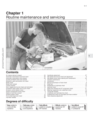 2
2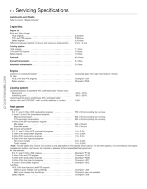 3
3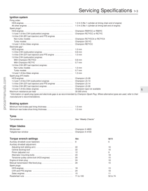 4
4 5
5 6
6 7
7 8
8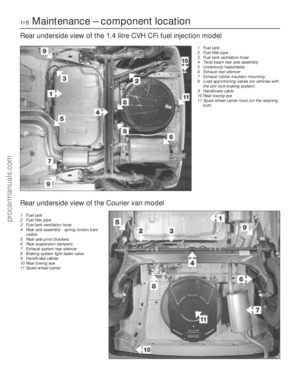 9
9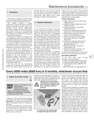 10
10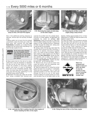 11
11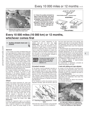 12
12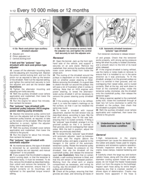 13
13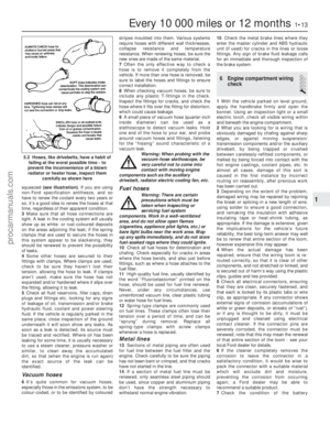 14
14 15
15 16
16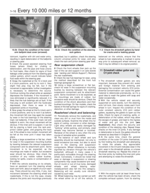 17
17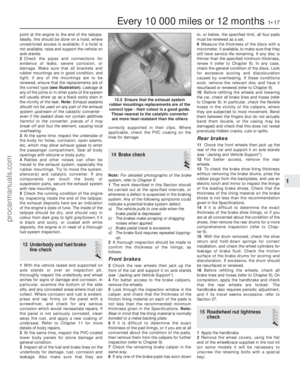 18
18 19
19 20
20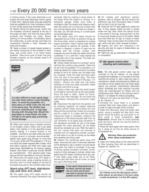 21
21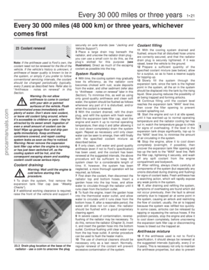 22
22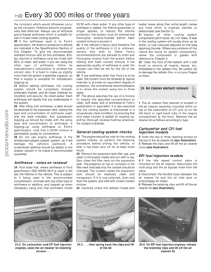 23
23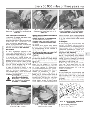 24
24 25
25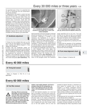 26
26 27
27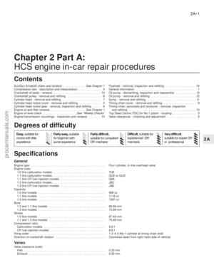 28
28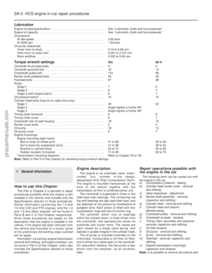 29
29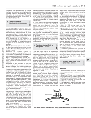 30
30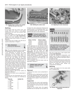 31
31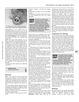 32
32 33
33 34
34 35
35 36
36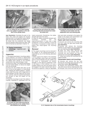 37
37 38
38 39
39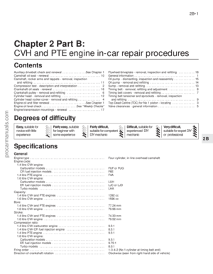 40
40 41
41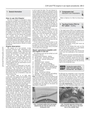 42
42 43
43 44
44 45
45 46
46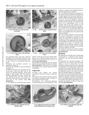 47
47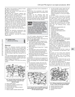 48
48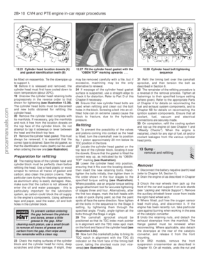 49
49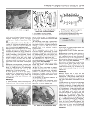 50
50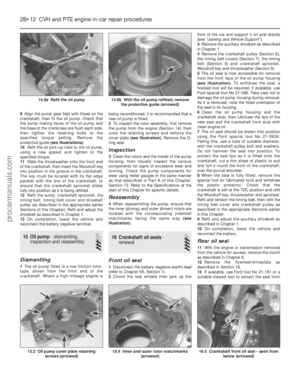 51
51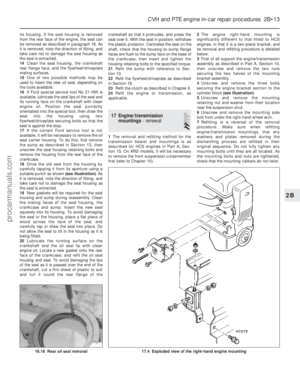 52
52 53
53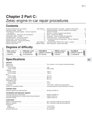 54
54 55
55 56
56 57
57 58
58 59
59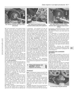 60
60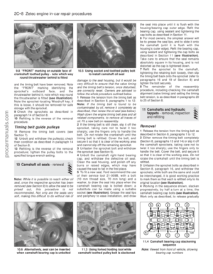 61
61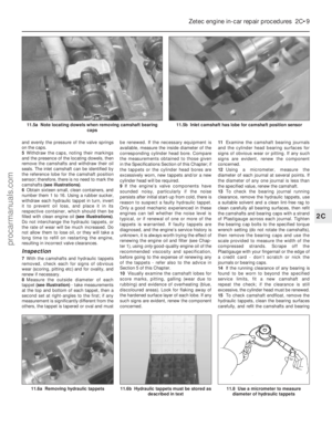 62
62 63
63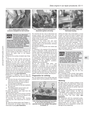 64
64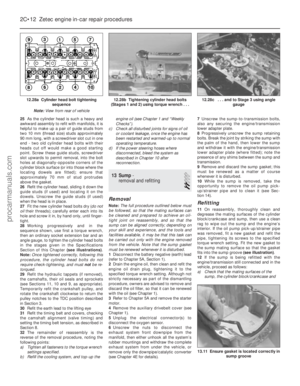 65
65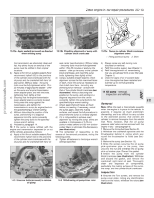 66
66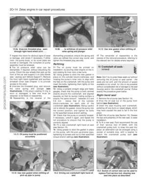 67
67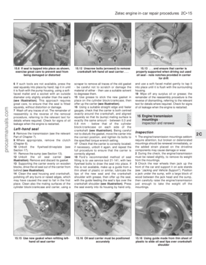 68
68 69
69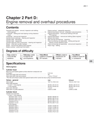 70
70 71
71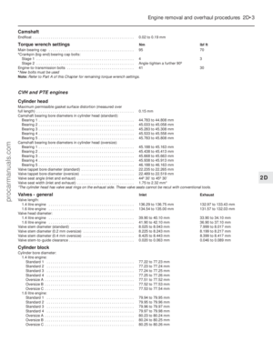 72
72 73
73 74
74 75
75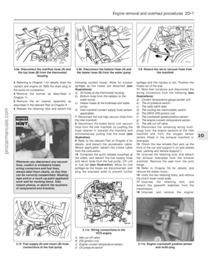 76
76 77
77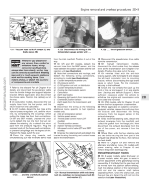 78
78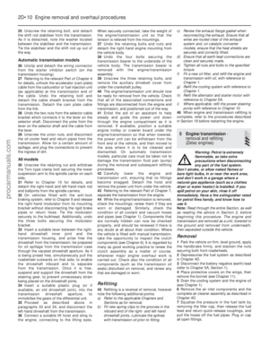 79
79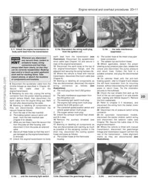 80
80 81
81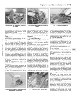 82
82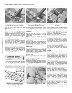 83
83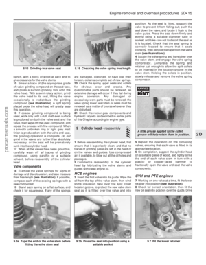 84
84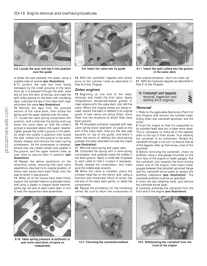 85
85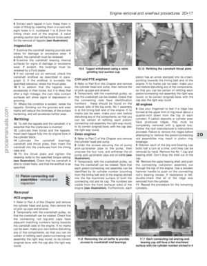 86
86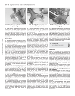 87
87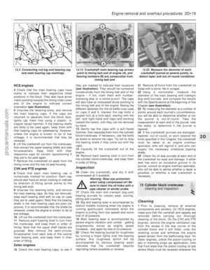 88
88 89
89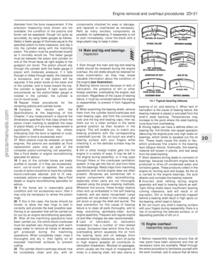 90
90 91
91 92
92 93
93 94
94 95
95 96
96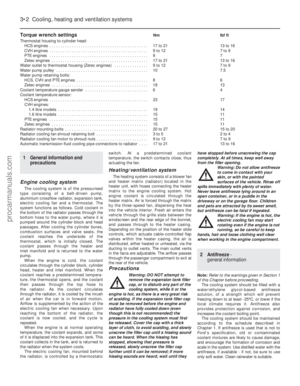 97
97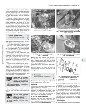 98
98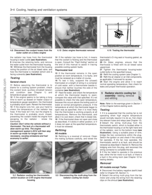 99
99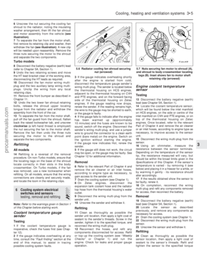 100
100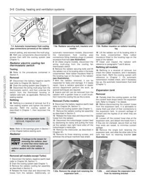 101
101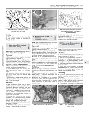 102
102 103
103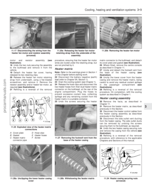 104
104 105
105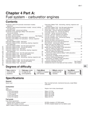 106
106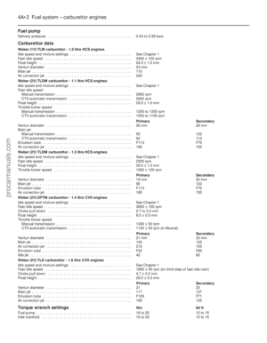 107
107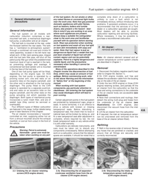 108
108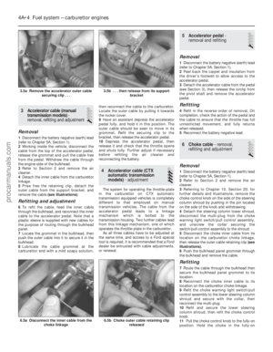 109
109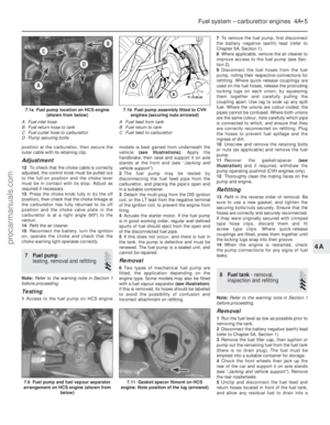 110
110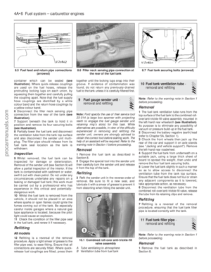 111
111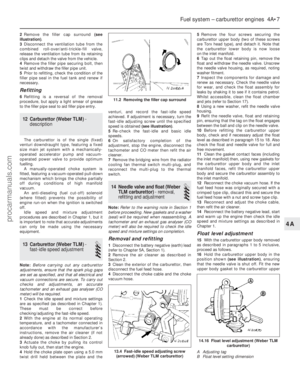 112
112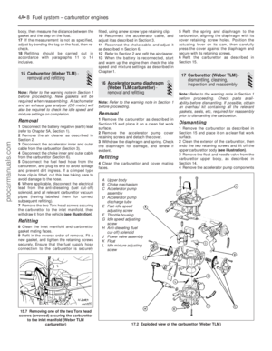 113
113 114
114 115
115 116
116 117
117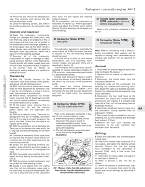 118
118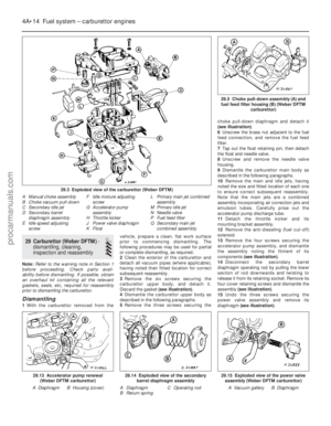 119
119 120
120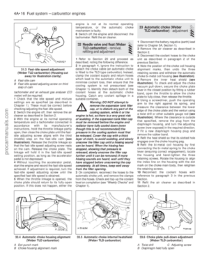 121
121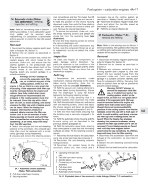 122
122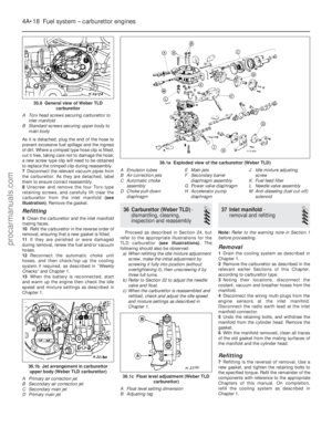 123
123 124
124 125
125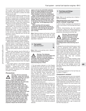 126
126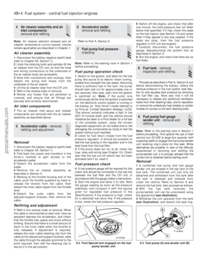 127
127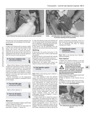 128
128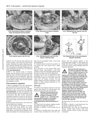 129
129 130
130 131
131 132
132 133
133 134
134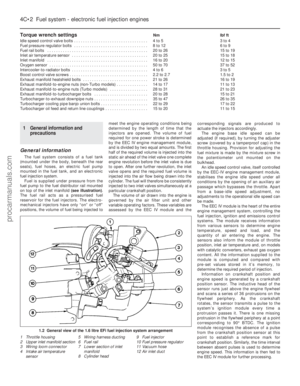 135
135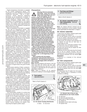 136
136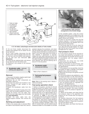 137
137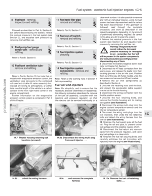 138
138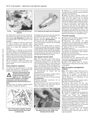 139
139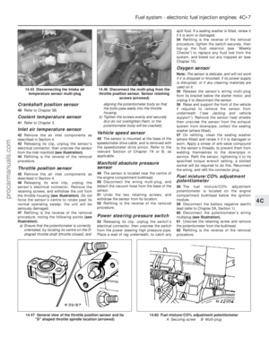 140
140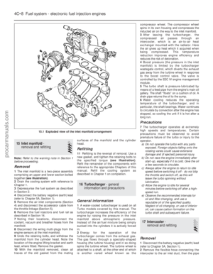 141
141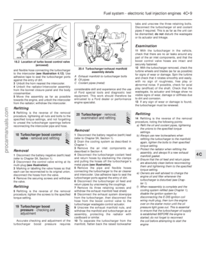 142
142 143
143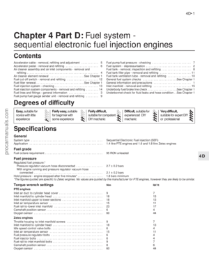 144
144 145
145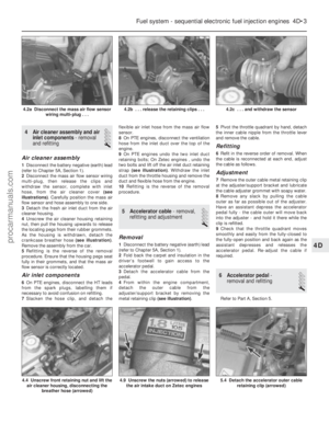 146
146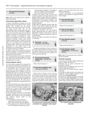 147
147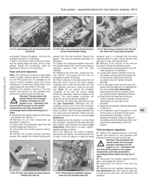 148
148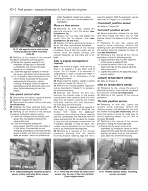 149
149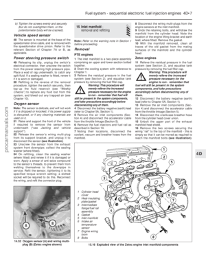 150
150 151
151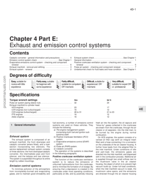 152
152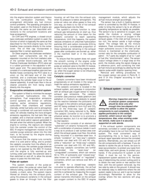 153
153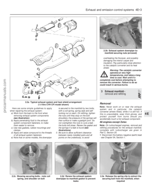 154
154 155
155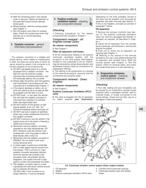 156
156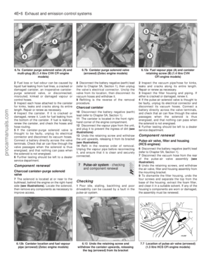 157
157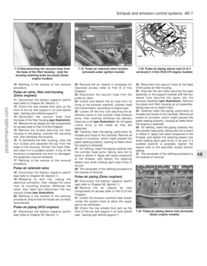 158
158 159
159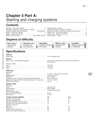 160
160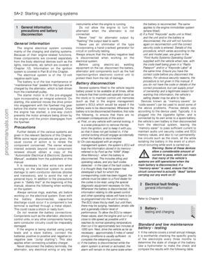 161
161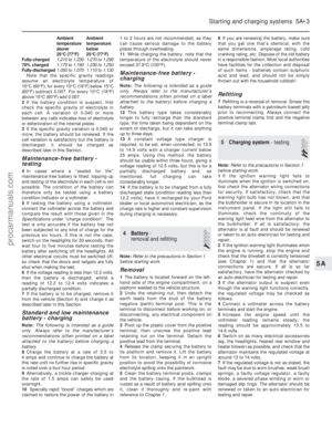 162
162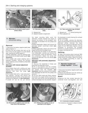 163
163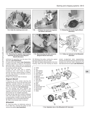 164
164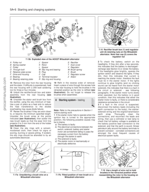 165
165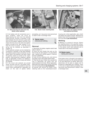 166
166 167
167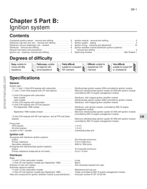 168
168 169
169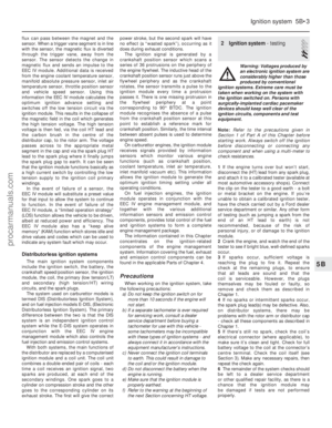 170
170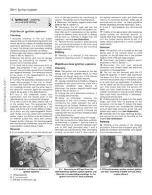 171
171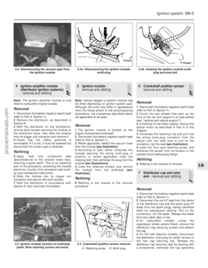 172
172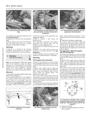 173
173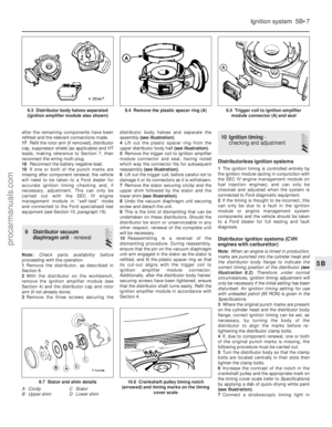 174
174 175
175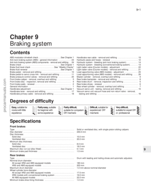 176
176 177
177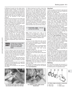 178
178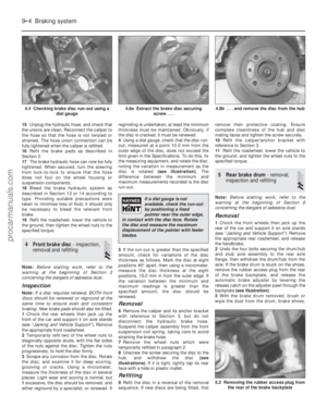 179
179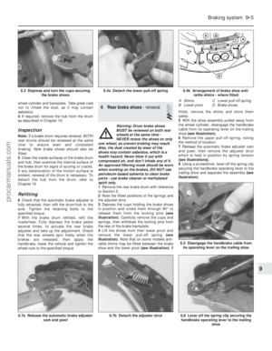 180
180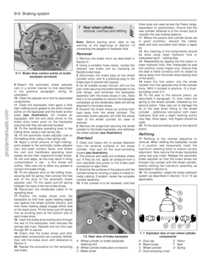 181
181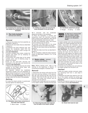 182
182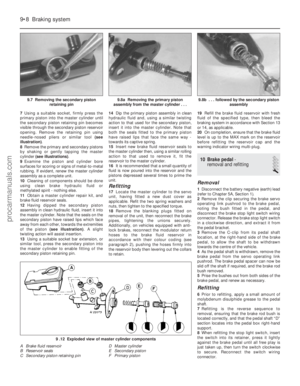 183
183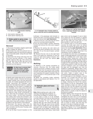 184
184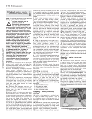 185
185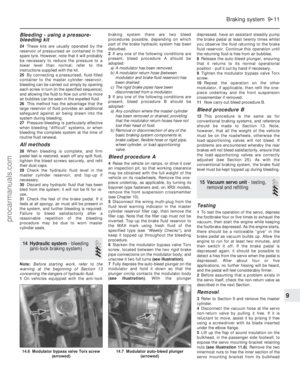 186
186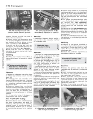 187
187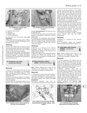 188
188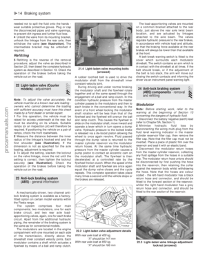 189
189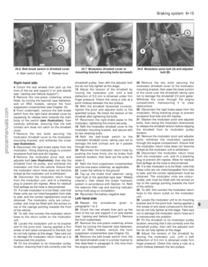 190
190 191
191 192
192 193
193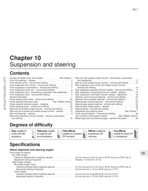 194
194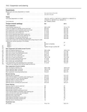 195
195 196
196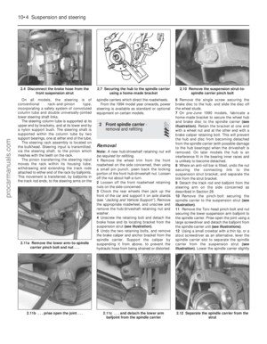 197
197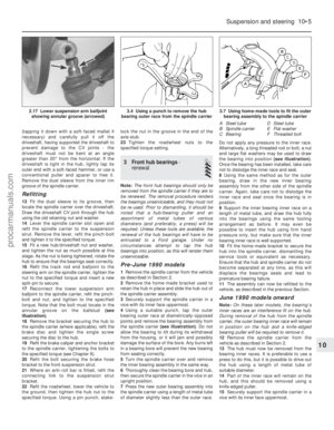 198
198 199
199 200
200 201
201 202
202 203
203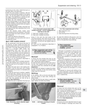 204
204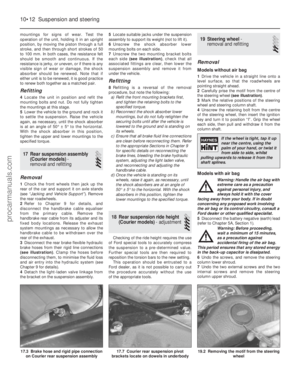 205
205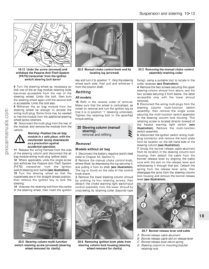 206
206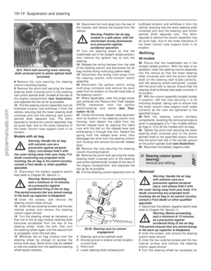 207
207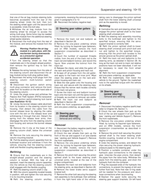 208
208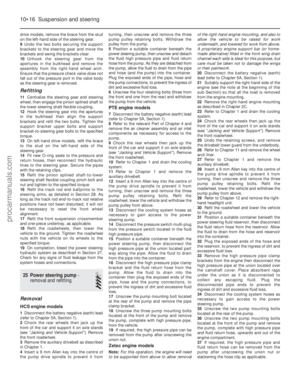 209
209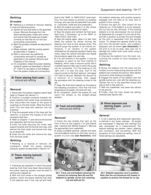 210
210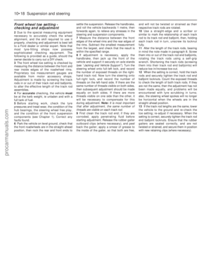 211
211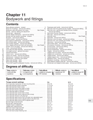 212
212 213
213 214
214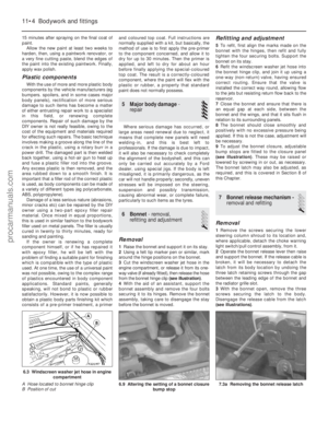 215
215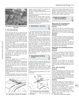 216
216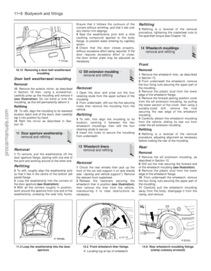 217
217 218
218 219
219 220
220 221
221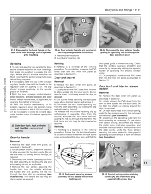 222
222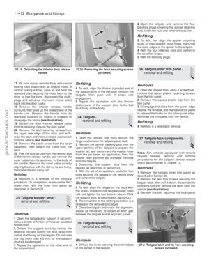 223
223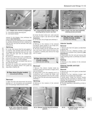 224
224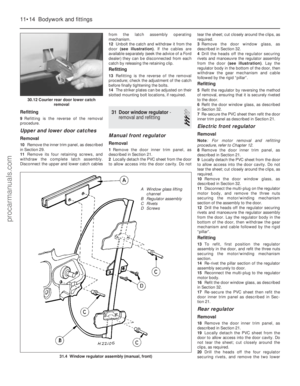 225
225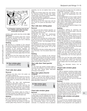 226
226 227
227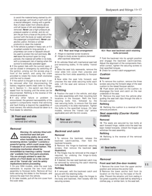 228
228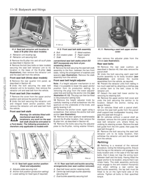 229
229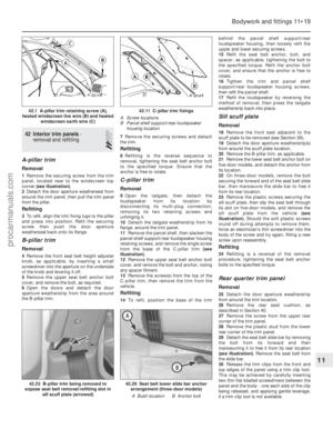 230
230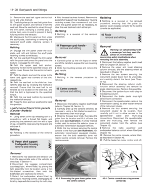 231
231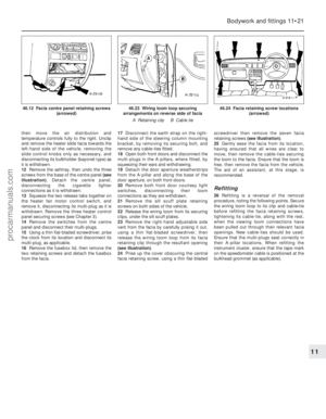 232
232 233
233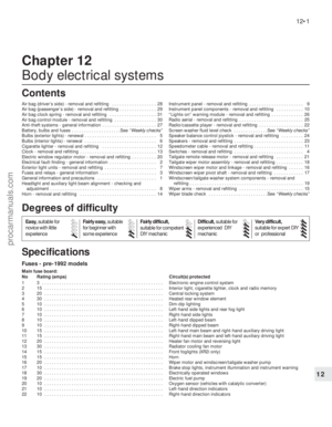 234
234 235
235 236
236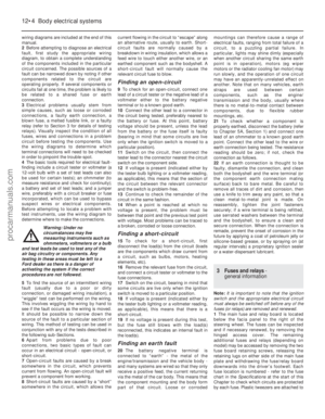 237
237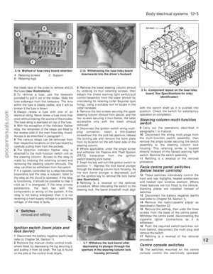 238
238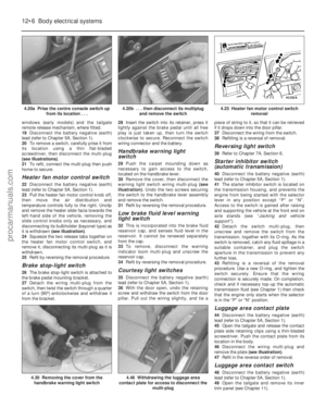 239
239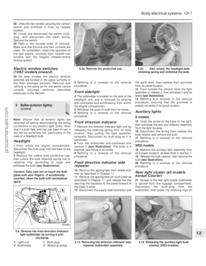 240
240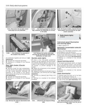 241
241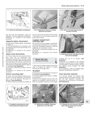 242
242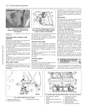 243
243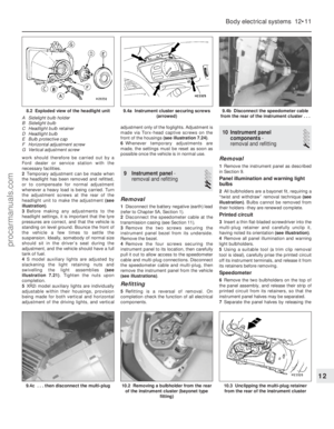 244
244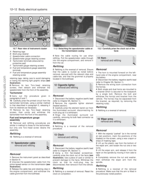 245
245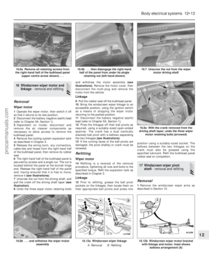 246
246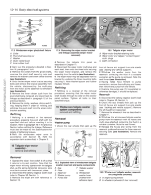 247
247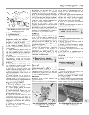 248
248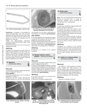 249
249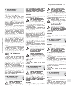 250
250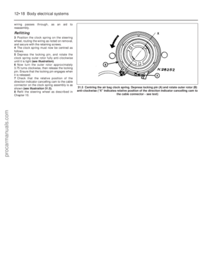 251
251 252
252 253
253 254
254 255
255 256
256 257
257 258
258 259
259 260
260 261
261 262
262 263
263 264
264 265
265 266
266 267
267 268
268 269
269 270
270 271
271 272
272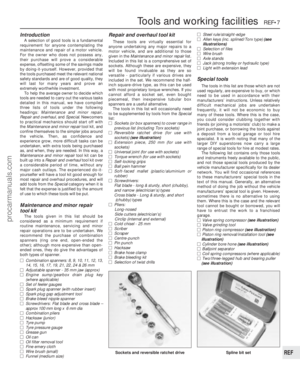 273
273 274
274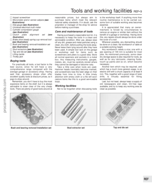 275
275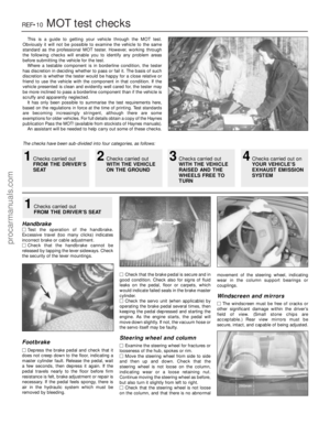 276
276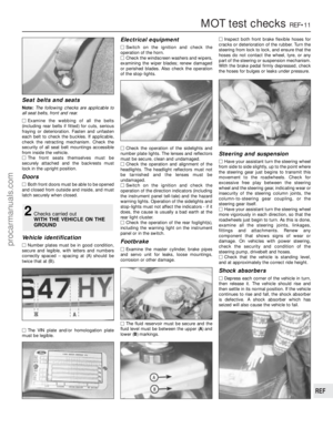 277
277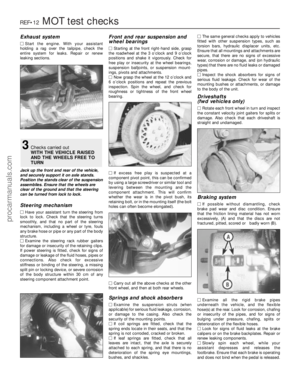 278
278 279
279 280
280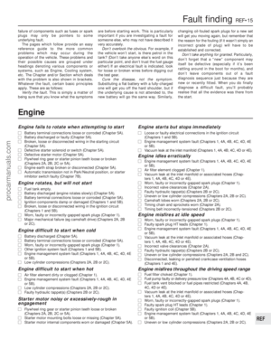 281
281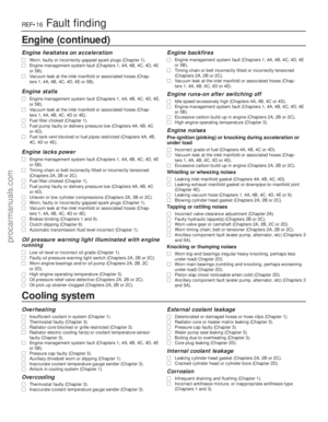 282
282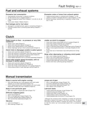 283
283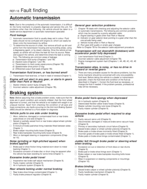 284
284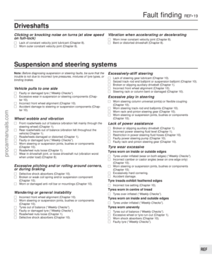 285
285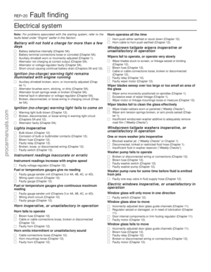 286
286 287
287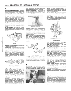 288
288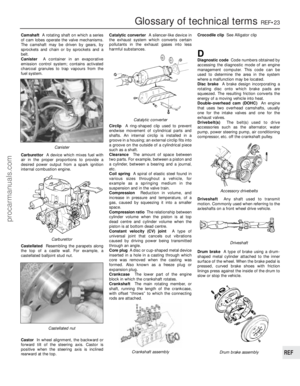 289
289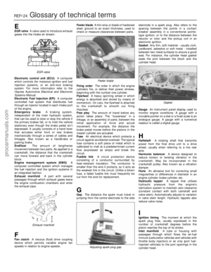 290
290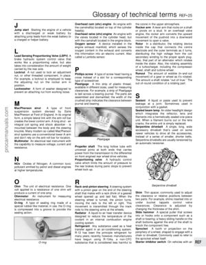 291
291 292
292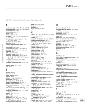 293
293 294
294 295
295