1989 FORD FIESTA fuse box
[x] Cancel search: fuse boxPage 30 of 296
connecting rods (after removing the cylinder
head and sump) without removing the engine.
However, this is not recommended. Work of
this nature is more easily and thoroughly
completed with the engine on the bench, as
described in Chapter 2D.
2 Compression test-
description and interpretation
2
1 When engine performance is down, or if
misfiring occurs which cannot be attributed to
the ignition or fuel systems, a compression
test can provide diagnostic clues as to the
engine’s condition. If the test is performed
regularly, it can give warning of trouble before
any other symptoms become apparent.
2 The engine must be fully warmed-up to
normal operating temperature, the oil level
must be correct and the battery must be fully
charged. The aid of an assistant will also be
required.
3 On fuel injection engines, refer to Chap-
ter 12 and remove the fuel pump fuse from the
fusebox. Now start the engine and allow it to
run until it stalls.
4 Disable the ignition system by
disconnecting the multi-plug from the DIS or
E-DIS ignition coil. Remove all the spark plugs
with reference to Chapter 1 if necessary.
5 Fit a compression tester to the No 1
cylinder spark plug hole - the type of tester
which screws into the plug thread is to be
preferred.
6 Arrange for an assistant to hold the
accelerator pedal fully depressed to the floor,
while at the same time cranking the engine
over for several seconds on the starter motor.
Observe the compression gauge reading. The
compression will build up fairly quickly in a
healthy engine. Low compression on the first
stroke, followed by gradually-increasing
pressure on successive strokes, indicates
worn piston rings. A low compression on the
first stroke which does not rise on successive
strokes, indicates leaking valves or a blown
head gasket (a cracked cylinder head could
also be the cause). Deposits on the underside
of the valve heads can also cause low
compression. Record the highest gauge
reading obtained, then repeat the procedure
for the remaining cylinders.
7 Due to the variety of testers available, and
the fluctuation in starter motor speed when
cranking the engine, different readings
are often obtained when carrying out
the compression test. For this reason, actual
compression pressure figures are not quoted
by Ford. However, the most important factor
is that the compression pressures are uniform
in all cylinders, and that is what this test is
mainly concerned with.
8 Add some engine oil (about three squirts
from a plunger type oil can) to each cylinder
through the spark plug holes, and then repeat
the test. 9
If the compression increases after the oil is
added, it is indicative that the piston rings are
definitely worn. If the compression does not
increase significantly, the leakage is occurring
at the valves or the head gasket. Leakage
past the valves may be caused by burned
valve seats and/or faces, or warped, cracked
or bent valves.
10 If two adjacent cylinders have equally low
compressions, it is most likely that the head
gasket has blown between them. The
appearance of coolant in the combustion
chambers or on the engine oil dipstick would
verify this condition.
11 If one cylinder is about 20 percent lower
than the other, and the engine has a slightly
rough idle, a worn lobe on the camshaft could
be the cause.
12 On completion of the checks, refit the
spark plugs and reconnect the HT leads and
the ignition coil plug. Refit the fuel pump fuse
to the fusebox.
3 Top Dead Centre (TDC) for No 1 piston - locating
2
1Top dead centre (TDC) is the highest point
of the cylinder that each piston reaches as the
crankshaft turns. Each piston reaches its TDC
position at the end of its compression stroke,
and then again at the end of its exhaust
stroke. For the purpose of engine timing, TDC
at the end of the compression stroke for No 1
piston is used. On the HCS engine, No 1
cylinder is at the crankshaft pulley/timing
chain end of the engine. Proceed as follows.
2 Ensure that the ignition is switched off.
Disconnect the HT leads from the spark plugs,
then unscrew and remove the plugs as
described in Chapter 1.
3 Turn the engine over by hand (using a
spanner on the crankshaft pulley) to the point
where the timing mark on the crankshaft
pulley aligns with the TDC (0) mark or TDC
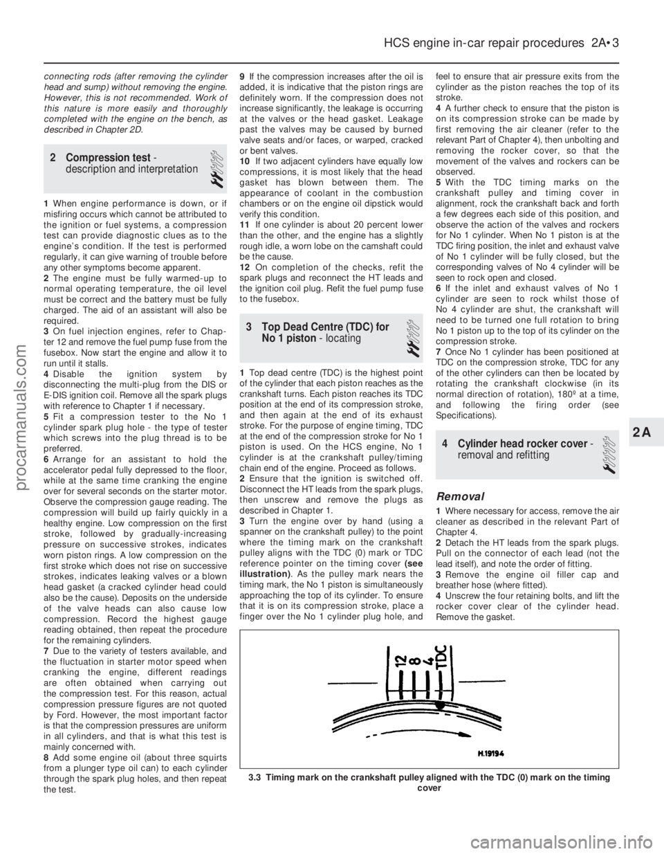
reference pointer on the timing cover (see
illustration) . As the pulley mark nears the
timing mark, the No 1 piston is simultaneously
approaching the top of its cylinder. To ensure
that it is on its compression stroke, place a
finger over the No 1 cylinder plug hole, and feel to ensure that air pressure exits from the
cylinder as the piston reaches the top of its
stroke.
4
A further check to ensure that the piston is
on its compression stroke can be made by
first removing the air cleaner (refer to the
relevant Part of Chapter 4), then unbolting and
removing the rocker cover, so that the
movement of the valves and rockers can be
observed.
5 With the TDC timing marks on the
crankshaft pulley and timing cover in
alignment, rock the crankshaft back and forth
a few degrees each side of this position, and
observe the action of the valves and rockers
for No 1 cylinder. When No 1 piston is at the
TDC firing position, the inlet and exhaust valve
of No 1 cylinder will be fully closed, but the
corresponding valves of No 4 cylinder will be
seen to rock open and closed.
6 If the inlet and exhaust valves of No 1
cylinder are seen to rock whilst those of
No 4 cylinder are shut, the crankshaft will
need to be turned one full rotation to bring
No 1 piston up to the top of its cylinder on the
compression stroke.
7 Once No 1 cylinder has been positioned at
TDC on the compression stroke, TDC for any
of the other cylinders can then be located by
rotating the crankshaft clockwise (in its
normal direction of rotation), 180º at a time,
and following the firing order (see
Specifications).
4 Cylinder head rocker cover -
removal and refitting
1
Removal
1 Where necessary for access, remove the air
cleaner as described in the relevant Part of
Chapter 4.
2 Detach the HT leads from the spark plugs.
Pull on the connector of each lead (not the
lead itself), and note the order of fitting.
3 Remove the engine oil filler cap and
breather hose (where fitted).
4 Unscrew the four retaining bolts, and lift the
rocker cover clear of the cylinder head.
Remove the gasket.
HCS engine in-car repair procedures 2A•3
3.3 Timing mark on the crankshaft pulley aligned with the TDC (0) mar\
k on the timing cover
2A
1595Ford Fiesta Remakeprocarmanuals.com
http://vnx.su
Page 91 of 296
necessary for reassembly of the engine are at
hand. In addition to all normal tools and
materials, jointing and thread locking
compound will be needed during engine
reassembly. For general-purpose applications,
it is recommended that Loctite 275 setting
sealer or Hylomar PL32M non-setting sealer
be used for joints where required, and
Loctite 270 for stud and bolt thread-locking.
For specific applications on Zetec engines,
Hylosil 102 for the cylinder block/crankcase-
to-sump/oil pump/oil seal carrier joints, and
Loctite 518 for the camshaft right-hand
bearing caps should be used. These are
recommended by, and obtained from, Ford
dealers. In all other cases, provided the
relevant mating surfaces are clean and flat,
new gaskets will be sufficient to ensure joints
are oil-tight. Do notuse any kind of silicone-
based sealant on any part of the fuel system or
inlet manifold, and neveruse exhaust sealants
upstream of the catalytic converter.
2 In order to save time and avoid problems,
engine reassembly can be carried out in the
following order (as applicable).
a) Engine ventilation cap (CVH and PTE engines).
b) Tappets and camshaft (HCS engines).
c) Crankshaft and main bearings.
d) Pistons and connecting rods.
e) Oil pump.
f) Sump.
g) Flywheel/driveplate.
h) Cylinder head.
i) Timing sprockets and chain/belt.
j) Engine external components.
3 Ensure that everything is clean prior to
reassembly. As mentioned previously, dirt and
metal particles can quickly destroy bearings
and result in major engine damage. Use clean
engine oil to lubricate during reassembly.
16 Piston rings - refitting
2
1Before installing new piston rings, check
the end gaps. Lay out each piston set with a
piston/connecting rod assembly, and keep them together as a matched set from now on.
2
Insert the top compression ring into the first
cylinder, and square it up with the cylinder
walls by pushing it in with the top of the
piston. The ring should be near the bottom of
the cylinder, at the lower limit of ring travel.
3 To measure the end gap, slip feeler gauges
between the ends of the ring, until a gauge
equal to the gap width is found. The feeler
gauge should slide between the ring ends
with a slight amount of drag. Compare the
measurement to the value given in the
Specifications in this Chapter; if the gap is
larger or smaller than specified, double-check to make sure you have the correct rings
before proceeding. If you are assessing the
condition of used rings, have the cylinder
bores checked and measured by a Ford
dealer or similar engine reconditioning
specialist, so that you can be sure of exactly
which component is worn, and seek advice as
to the best course of action to take.
4 If the end gap is still too small, it must be
opened up by careful filing of the ring ends
using a fine file. If it is too large, this is not as
serious, unless the specified limit is exceeded,
in which case very careful checking is
required of the dimensions of all components,
as well as of the new parts.
5 Repeat the procedure for each ring that will
be installed in the first cylinder, and for each
ring in the remaining cylinders. Remember to
keep rings, pistons and cylinders matched up.
6 Refit the piston rings as follows. Where the
original rings are being refitted, use the marks
or notes made on removal, to ensure that
each ring is refitted to its original groove and
the same way up. New rings generally have
their top surfaces identified by markings
(often an indication of size, such as “STD”, or
the word “TOP”) - the rings must be fitted with
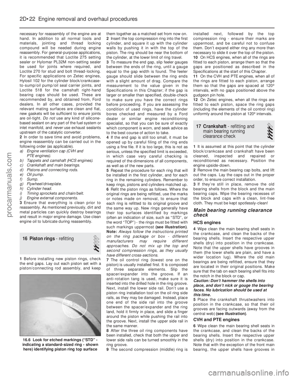
such markings uppermost (see illustration) .
Note: Always follow the instructions printed
on the ring package or box - different
manufacturers may require different
approaches. Do not mix up the top and
second compression rings, as they usually
have different cross-sections.
7 The oil control ring (lowest one on the
piston) is usually installed first. It is composed
of three separate elements. Slip the
spacer/expander into the groove. If an
anti- rotation tang is used, make sure it is
inserted into the drilled hole in the ring groove.
Next, install the lower side rail. Don’t use a
piston ring installation tool on the oil ring side
rails, as they may be damaged. Instead, place
one end of the side rail into the groove
between the spacer/expander and the ring
land, hold it firmly in place, and slide a finger
around the piston while pushing the rail into
the groove. Next, install the upper side rail in
the same manner.
8 After the three oil ring components have
been installed, check that both the upper and
lower side rails can be turned smoothly in the
ring groove.
9 The second compression (middle) ring is installed next, followed by the top
compression ring - ensure their marks are
uppermost, and be careful not to confuse
them. Don’t expand either ring any more than
necessary to slide it over the top of the piston.
10
On HCS engines, when all of the rings are
fitted to each piston, arrange them so that the
gaps are positioned as described in the
Specifications at the start of this Chapter.
11 On the CVH and PTE engines, when all of
the rings are fitted to each piston, arrange
them so that the gaps are spaced at 120º
intervals, with no gaps positioned above the
gudgeon pin hole.
12 On Zetec engines, when all the rings are
fitted to each piston, space the ring gaps
(including the elements of the oil control ring)
uniformly around the piston at 120º intervals.
17 Crankshaft - refitting and
main bearing running
clearance check
4
1 It is assumed at this point that the cylinder
block/crankcase and crankshaft have been
cleaned, inspected and repaired or
reconditioned as necessary. Position the
engine upside-down.
2 Remove the main bearing cap bolts, and lift
out the caps. Lay the caps out in the proper
order, to ensure correct installation.
3 If they’re still in place, remove the old
bearing shells from the block and the main
bearing caps. Wipe the bearing recesses of
the block and caps with a clean, lint-free
cloth. They must be kept spotlessly-clean!
Main bearing running clearance
check
HCS engines
4 Wipe clean the main bearing shell seats in
the crankcase, and clean the backs of the
bearing shells. Insert the respective upper
shells (dry) into position in the crankcase.
Note that the upper shells have grooves in
them (the lower shells are plain, and have a
wider location lug). Where the old main
bearings are being refitted, ensure that they
are located in their original positions. Make
sure that the tab on each bearing shell fits into
the notch in the block or cap.
Caution: Don’t hammer the shells into
place, and don’t nick or gouge the bearing
faces. No lubrication should be used at
this time.
5 Place the crankshaft thrustwashers into
position in the crankcase, so that their oil
grooves are facing outwards (away from the
central web) (see illustration) .
CVH and PTE engines
6Wipe clean the main bearing shell seats in
the crankcase, and clean the backs of the
bearing shells. Insert the respective upper
shells (dry) into position in the crankcase.
Note that with the exception of the front main
bearing, the upper shells have grooves in
2D•22 Engine removal and overhaul procedures
16.6 Look for etched markings (“STD” -
indicating a standard-sized ring - shown
here) identifying piston ring top surface
1595Ford Fiesta Remakeprocarmanuals.com
http://vnx.su
Page 127 of 296
4 Air cleaner assembly and airinlet components -
removal and refitting
1
Note: Air cleaner element renewal and air
cleaner temperature control system checks
(where applicable) are described in Chapter 1.
Air cleaner assembly
1 Disconnect the battery negative (earth) lead
(refer to Chapter 5A, Section 1).
2 Undo the retaining bolts and partially lift the
air cleaner from the CFi unit, so that the hose
and wiring connections to the underside of
the air cleaner body are accessible.
3 Note their connections and routings, then
detach the wiring and hoses from the
underside of the air cleaner.
4 Lift the air cleaner clear from the CFi unit.
5 Refit in the reverse order of removal.
6 Renew any hoses that are perished or
cracked, and ensure that all fittings are
securely and correctly reconnected.
Air inlet components
7 The air cleaner inlet spout and related
components are removed with the air cleaner
assembly as described above.
5 Accelerator cable - removal,
refitting and adjustment
1
Removal
1 Disconnect the battery negative (earth) lead
(refer to Chapter 5A, Section 1).
2 Fold back the carpet and insulation in the
driver’s footwell to gain access to the
accelerator pedal.
3 Detach the accelerator cable from the
pedal.
4 Remove the air cleaner assembly as
described in Section 4.
5 Working at the throttle housing end of the
cable, pivot the throttle quadrant by hand to
release the tension from the cable, then
detach the inner cable nipple from the throttle
lever.
6 Detach the outer cable from the
adjuster/support bracket, then remove the
cable.
Refitting and adjustment
7 Refit in the reverse order of removal. When
the cable is reconnected at each end, have an
assistant depress the accelerator, and check
that the throttle fully opens and shuts without
binding. Ensure that there is a small amount of
slack in the inner cable when the throttle is
fully released. If adjustment is required,
release the outer cable retaining clip from the
cable at the adjustment/support bracket, slide
the cable through the adjuster grommet to the
point required, then refit the retaining clip to
secure it in the set position.
6 Accelerator pedal -
removal and refitting
1
Refer to Part A, Section 5.
7 Fuel pump/fuel pressure -
checking
3
Note: Refer to the warning note in Section 1
before proceeding.
Fuel pump operation check
1 Switch on the ignition, and listen for the fuel
pump (the sound of an electric motor running,
audible from beneath the rear seats). Assuming
there is sufficient fuel in the tank, the pump
should start and run for approximately one or
two seconds, then stop, each time the ignition
is switched on. Note:If the pump runs
continuously all the time the ignition is switched
on, the electronic control system is running in
the backup (or “limp-home”) mode referred to
by Ford as “Limited Operation Strategy” (LOS).
This almost certainly indicates a fault in the
EEC IV module itself, and the vehicle should
therefore be taken to a Ford dealer for a full test
of the complete system, using the correct
diagnostic equipment; do not waste time or risk
damaging the components by trying to test the
system without such facilities.
2 Listen for fuel return noises from the fuel
pressure regulator. It should be possible to
feel the fuel pulsing in the regulator and in the
feed hose from the fuel filter.
3 If the pump does not run at all, check the
fuse, relay and wiring (see Chapter 12). Check
also that the fuel cut-off switch has not been
activated and if so, reset it.
Fuel pressure check
4 A fuel pressure gauge will be required for this
check and should be connected in the fuel line
between the fuel filter and the CFi unit, in
accordance with the gauge maker’s instructions.
5 Start the engine and allow it to idle. Note
the gauge reading as soon as the pressure
stabilises, and compare it with the figures
given for regulated fuel pressure in the
Specifications . If the pressure is high, check
for a restricted fuel return line. If the pressure
is low, renew the fuel pressure regulator. 6
Switch off the engine, and check that after
one minute, the hold pressure has not fallen
below that specified. If it has, check the seals
on the fuel injector (see Section 14) and renew
them if they appear in any way suspect. If the
seals are okay, then the fuel pressure
regulator or CFi unit are suspect.
7 Carefully disconnect the fuel pressure
gauge, depressurising the system first as
described in Section 2.
8 Run the engine, and check that there are no
fuel leaks.
8 Fuel tank - removal,
inspection and refitting
3
Proceed as described in Part A, Section 8, but
before disconnecting the battery, relieve the
residual pressure in the fuel system (see Sec-
tion 2), and equalise tank pressure by removing
the fuel filler cap. Note also that it will be
necessary to release any additional ventilation
tubes from their retaining clips, and to reposition
or remove the underbody heat shields on certain
models for access to the tank retaining bolts.
9 Fuel pump/fuel gauge
sender unit - removal and
refitting
3
Note: Refer to the warning note in Section 1
before proceeding. Ford specify the use of their
service tool 23-026 (a large box spanner with
projecting teeth to engage the fuel pump/sender
unit retaining ring’s slots) for this task. While
alternatives are possible, in view of the difficulty
experienced in removing and refitting the
pump/sender unit, it is strongly advised that the
correct tool is obtained before starting work.
Removal
1 A combined fuel pump and fuel gauge
sender unit are located in the top face of the
fuel tank. The combined unit can only be
detached and withdrawn from the tank after
the tank is released and lowered from
under the vehicle. Refer to Section 8 and
remove the fuel tank, then proceed as follows.
2 With the fuel tank removed, the
pump/sender unit can be unscrewed using
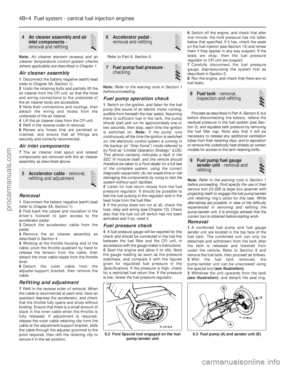
the special tool (see illustration) .
3 Withdraw the unit upwards from the tank
(see illustration) , and detach the seal ring.
9.3 Fuel pump (A) and sender unit (B)
4B•4 Fuel system - central fuel injection engines
9.2 Ford Special tool engaged on the fuel
pump/sender unit
1595Ford Fiesta Remakeprocarmanuals.com
http://vnx.su
Page 232 of 296
then move the air distribution and
temperature controls fully to the right. Unclip
and remove the heater slide facia towards the
left-hand side of the vehicle, removing the
slide control knobs only as necessary, and
disconnecting its bulbholder (bayonet type) as
it is withdrawn.
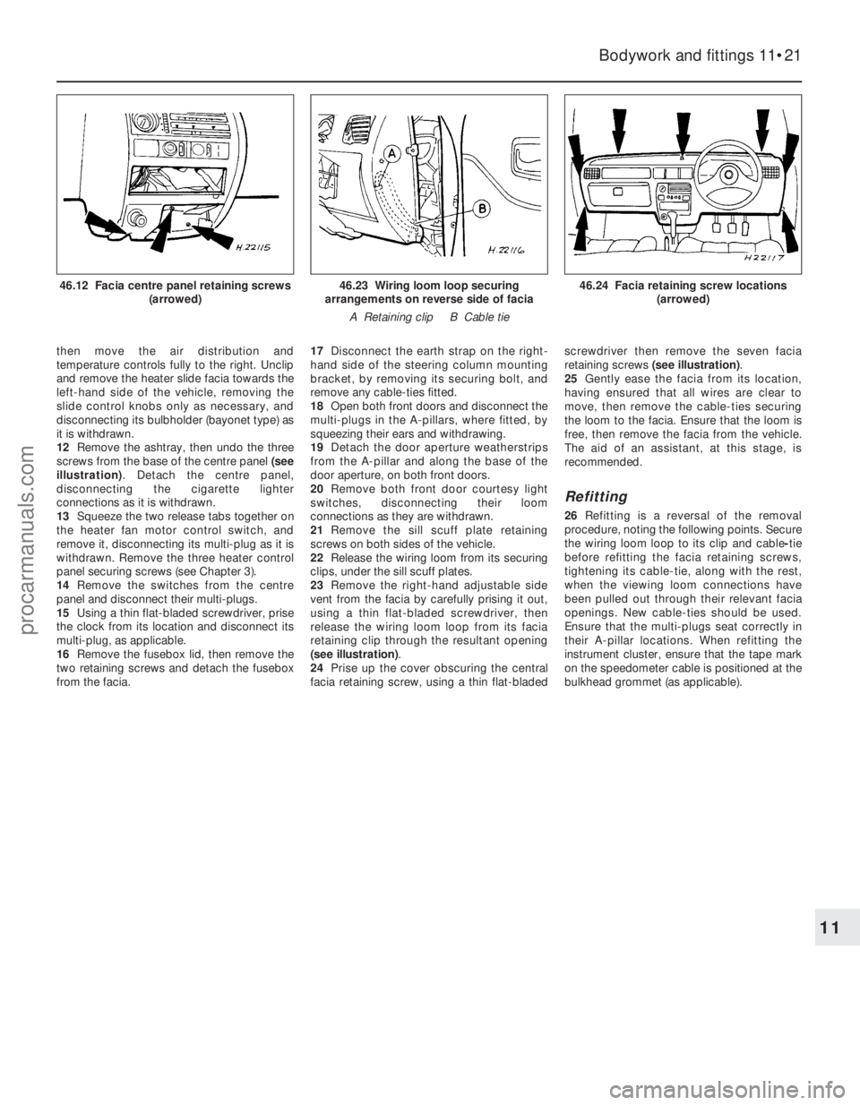
12Remove the ashtray, then undo the three
screws from the base of the centre panel (see
illustration) . Detach the centre panel,
disconnecting the cigarette lighter
connections as it is withdrawn.
13 Squeeze the two release tabs together on
the heater fan motor control switch, and
remove it, disconnecting its multi-plug as it is
withdrawn. Remove the three heater control
panel securing screws (see Chapter 3).
14 Remove the switches from the centre
panel and disconnect their multi-plugs.
15 Using a thin flat-bladed screwdriver, prise
the clock from its location and disconnect its
multi-plug, as applicable.
16 Remove the fusebox lid, then remove the
two retaining screws and detach the fusebox
from the facia. 17
Disconnect the earth strap on the right-
hand side of the steering column mounting
bracket, by removing its securing bolt, and
remove any cable-ties fitted.
18 Open both front doors and disconnect the
multi-plugs in the A-pillars, where fitted, by
squeezing their ears and withdrawing.
19 Detach the door aperture weatherstrips
from the A-pillar and along the base of the
door aperture, on both front doors.
20 Remove both front door courtesy light
switches, disconnecting their loom
connections as they are withdrawn.
21 Remove the sill scuff plate retaining
screws on both sides of the vehicle.
22 Release the wiring loom from its securing
clips, under the sill scuff plates.
23 Remove the right-hand adjustable side
vent from the facia by carefully prising it out,
using a thin flat-bladed screwdriver, then
release the wiring loom loop from its facia
retaining clip through the resultant opening
(see illustration) .
24 Prise up the cover obscuring the central
facia retaining screw, using a thin flat-bladed screwdriver then remove the seven facia
retaining screws
(see illustration) .
25 Gently ease the facia from its location,
having ensured that all wires are clear to
move, then remove the cable-ties securing
the loom to the facia. Ensure that the loom is
free, then remove the facia from the vehicle.
The aid of an assistant, at this stage, is
recommended.
Refitting
26 Refitting is a reversal of the removal
procedure, noting the following points. Secure
the wiring loom loop to its clip and cable -tie
before refitting the facia retaining screws,
tightening its cable-tie, along with the rest,
when the viewing loom connections have
been pulled out through their relevant facia
openings. New cable-ties should be used.
Ensure that the multi-plugs seat correctly in
their A-pillar locations. When refitting the
instrument cluster, ensure that the tape mark
on the speedometer cable is positioned at the
bulkhead grommet (as applicable).
Bodywork and fittings 11•21
46.24 Facia retaining screw locations (arrowed)46.23 Wiring loom loop securing
arrangements on reverse side of facia
A Retaining clip B Cable tie46.12 Facia centre panel retaining screws (arrowed)
11
1595Ford Fiesta Remakeprocarmanuals.com
http://vnx.su
Page 294 of 296
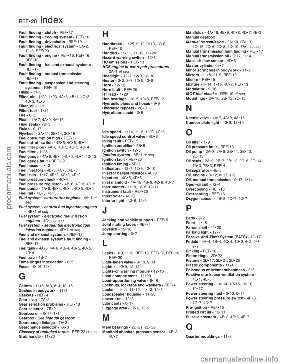
Fault finding - clutch - REF•17
Fault finding - cooling system - REF•16
Fault finding - driveshafts - REF•19
Fault finding - electrical system - 5A•2,
12 •3, REF •20
Fault finding - engine - REF•15, REF•16,
REF•18
Fault finding - fuel and exhaust systems -
REF•17
Fault finding - manual transmission - REF•17
Fault finding - suspension and steering
systems - REF•19
Filling - 11•3
Filter, air -1•22, 1•23, 4A•3, 4B•4, 4C•3,
4D•3, 4E•5
Filter, oil -1•9
Filter, fuel -1•25
Fire - 0•5
Float - 4A•7, 4A•9, 4A•16
Fluid seals - 7B•3
Fluids - 0•17
Flywheel - 2A•11, 2B•14, 2C•16
Fuel consumption high - REF•17
Fuel cut-off switch - 4B•5, 4C•5, 4D•4
Fuel filler pipe - 4A•6, 4B•5, 4C•5, 4D•4
Fuel filter - 1•25
Fuel gauge - 4A•6, 4B•4, 4C•5, 4D•4, 12 •12
Fuel gauge fault - REF•20
Fuel hoses - 1•13
Fuel injectors - 4B•5, 4C•5, 4D•5
Fuel lines - 1•17, 4B•3, 4C•3, 4D•2
Fuel pressure check - 4C•4
Fuel pressure regulator - 4B•6, 4C•6, 4D•5
Fuel pump - 4A•5, 4B•4, 4C•4, 4C•5, 4D•4
Fuel rail - 4C•5, 4D•5
Fuel system - carburettor engines -4A•1 et
seq
Fuel system - central fuel injection engines
-4B•1 et seq
Fuel system - electronic fuel injection engines -4C•1 et seq
Fuel system - sequential electronic fuel
injection engines -4D•1 et seq
Fuel and exhaust systems - REF•13
Fuel and exhaust systems fault finding - REF•17
Fuel tank - 4A•5, 4A•6, 4B•4, 4B•5, 4C•5,
4D•4
Fuel trap - 4B•7
Fume or gas intoxication - 0•5
Fuses - 0•16, 12 •4
G
Gaiters - 1•16, 8•3, 8•4, 10 •15
Gashes in bodywork - 11•3
Gaskets - REF •4
Gear lever - 7A•2
Gear selection problems - REF•18
Gear selector - 7B•2
Gearbox oil - 0•17, 1•14
Gearbox - See Manual gearbox
Gearchange linkage - 7A•2
Gearchange selector - 7A•3
Glossary of technical terms - REF•22 et seq
Grab handle - 11•20
H
Handbrake - 1•25, 9•12, 9•13, 12 •6,
REF•10
Handles - 11•11, 11•13, 11 •20
Hazard warning switch - 12•8
HC emissions - REF•13
HCS engine in-car repair procedures -
2A•1 et seq
Headlight - 12•7, 12 •9, 12 •10
Heater - 3•2, 3•8, 12 •6, 12•9
Horn - 12•12
Horn fault - REF•20
HT lead - 1•20
Hub bearings - 10•5, 10•8, REF •12
Hydraulic pipes and hoses - 9•9
Hydraulic tappets - 2C•8
Hydrofluoric acid - 0•5
I
Idle speed -1•14, 1•15, 1•20, 4C•6
Idle speed control valve - 4D•6
Idling fault - REF•15
Ignition amplifier - 5B•5
Ignition switch - 12•5
Ignition system -5B•1 et seq
Ignition fault - REF•20
Ignition timing - 5B•7
Indicators - 12•7, 12•9, 12 •10
Injector ballast resistor - 4B•9
Injectors - 4C•5, 4D•5
Inlet manifold - 4A•18, 4B•9, 4C•8, 4D•7
Instruments - 1•18, 12•8, 12•11
Instrument fault - REF•20
Intercooler - 4C•8
Interior light - 12•6, 12 •9
J
Jacking and vehicle support - REF•5
Joint mating faces - REF•4
Joystick - 12•16
Jump starting - 0•7
L
Leaks -0•9, 1•12, REF •16, REF•17, REF•18,
REF•20
Light-laden valve - 9•13, 9•14
Lighter - 12•9, 12 •12
Lights-on warning module - 12•16
Load compartment - 11•20
Load-apportioning valve - 9•16
Locknuts ,locktabs and washers - REF•4
Locks - 11•11, 11•12, 11•13, 12 •5
Loudspeaker housing - 11•20
Lower arm - 10•8
Lubricants - 0•17
Luggage area - 12•6, 12•9
M
Main bearings - 2D•21, 2D•22
Manifold absolute pressure sensor - 4B•8,
4C•7 Manifolds -
4A•18, 4B•9, 4C•8, 4D•7, 4E•3
Manual gearbox
Manual transmission -2A•10, 2B•13,
2C•15, 2D•6, 2D•8, 2D•10, 7A•1 et seq
Manual transmission fault finding - REF•17
Manual transmission oil - 0•17, 1•14
Mass air flow sensor - 4D•6
Master cylinder - 9•7
Minor scratches in bodywork - 11•2
Mirrors - 11 •8, 11•9, REF •10
Misfire - REF•15
Mixture - 1•14, 1•15, 4C•7, REF•13
Modulator - 9•16
MOT test checks - REF•10et seq
Mountings - 2A•10, 2B•13, 2C•15
N
Needle valve - 4A•7, 4A•9, 4A•16
Number plate light - 12•8, 12 •10
O
Oil filter - 1•9
Oil pressure fault - REF•16
Oil pump - 2A•8, 2A•9, 2B•11, 2B•12,
2C•13
Oil seals - 2A•9, 2B•7, 2B•12, 2C•8, 2C•14,
7A•3, 7B•3, REF •4
Oil separator - 4E•5
Oil, engine - 0•12, 0•17, 1•9
Oil, manual transmission - 0•17, 1•14
Open-circuit - 12•4
Overcooling - REF•16
Overheating - REF•16
Oxygen sensor - 4B•8, 4C•7, 4D•7
P
Pads -9•2
Paint - 1•18
Parcel shelf - 11•20
Parking light - 12•7
Passive Anti-Theft System (PATS) - 12•17
Pedals - 4A•4, 4B•4, 4C•4, 4D•3, 6•2, 9•8,
9•9
Pinking - REF•16
Piston rings - 2D•22
Pistons - 2D•17, 2D•24, 2D•25
Plastic components - 11•4
Poisonous or irritant substances - 0•5
Positive crankcase ventilation system - 4E•1, 4E•5
Power steering - 10•14, 10•15, 10•16,
10 •17
Power steering fluid - 0•13, 0•17
Power steering pressure switch - 4B•8,
4C•7, 4D•7
Pre-ignition - REF•16
Printed circuit - 12•11
Pulse-air system - 4E•2, 4E•6, 4E•7
Q
Quarter mouldings - 11•8
REF•28Index
1595 Ford Fiesta Remakeprocarmanuals.com
http://vnx.su