Page 337 of 408

BRAKE OPERATING SYSTEM 9-2
BASIC OPERATING PRINCIPLES 9-2
DISC BRAKES 9-2
DRUM BRAKES 9-2
POWERBOOSTERS 9-2
BRAKE LIGHT SWITCH 9-3
REMOVAL&INSTALLATION 9-3
MASTER CYLINDER 9-3
REMOVAL&INSTALLATION 9-3
' BRAKE PEDAL ADJUSTMENTS 9-4
POWER BRAKEBOOSTER 9-5
REMOVAL &INSTALLATION 9-5
PROPORTIONING VALVE 9-6
REMOVAL &INSTALLATION 9-6
BRAKEHOSESAND LINES 9-6
REMOVAL&INSTALLATION 9-6
BLEEDING BRAKESYSTEM 9-7
DISC BRAKES 9-8
BRAKE PADS 9-8
REMOVAL &INSTALLATION 9-8
INSPECTION 9-11
BRAKE CALIPER 9-11
REMOVAL & INSTALLATION 9-11
OVERHAUL 9-12
BRAKE DISC (ROTOR) 9-13
REMOVAL &INSTALLATION 9-13
INSPECTION 9-14
DRUM BRAKES 9-15
BRAKEDRUMS 9-16
REMOVAL &INSTALLATION 9-16
INSPECilON 9-16
BRAKESHOES 9-16
INSPECTION 9-16
REMOVAL&INSTALLATION 9-17
ADJUSTMENTS 9-18
WHEELCYLINDERS 9-19
REMOVAL &INSTALLATION 9-19
. OVERHAUL 9-19
PARKING BRAKE 9-20
CABLE(S) 9-20
REMOVAL&INSTALLATION 9-20
ADJUSTMENT 9-22
BRAKESHOES 9-23
REMOVAL &INSTALLATION 9-23
ADJUSTMENT 9-24
ANTI-LOCKBRAKE SYSTEM 9-24
GENERAL INFORMATION 9-24
PRECAUTIONS 9-24
DIAGNOSIS AND TESTING 9-24
HYDRAULIC CONTROL UNIT 9-25
REMOVAL&INSTALLATION 9-25
ANTI-LOCK CONTROL UNIT 9-27
REMOVAL&INSTALLATION 9-27
SPEED SENSORS 9-28
REMOVAL &INSTALLATION 9-28
b G-SENSOR 9-29
REMOVAL &INSTALLATION 9-29
' TONE (EXCITER) RING 9-29
REMOVAL&INSTALLATION 9-29
BLEEDINGTHEABSSYSTEM 9-30 COMPONENTLOCATIONS
DRUM BRAKECOMPONENTS 9-15
SPECIFICATIONS CHARTS
ABS DIAGNOSTICTROUBLE CODES 9-25
BRAKE SPECIFICATIONS 9-31
Page 338 of 408

9-2 BRAKES
Hydraulic systems are used to actuate the brakes
of all modern automobiles. The system transports the
power required to force the frictional surfaces of the
braking system together from the pedal to the indi-
vidual brake units at each wheel. A hydraulic system
is used for two reasons.
First, fluid under pressure can be carried to all
parts of an automobile by small pipes and flexible
hoses without taking up a significant amount of room
or posing routing problems.
Second, a great mechanical advantage can be
given to the brake pedal end of the system, and the
foot pressure required to actuate the brakes can be
reduced by making the surface area of the master
cylinder pistons smaller than that of any of the pis-
tons in the wheel cylinders or calipers.
The master cylinder consists of a fluid reservoir
along with a double cylinder and piston assembly.
Double type master cylinders are designed to sepa-
rate the front and rear braking systems hydraulically
in case of a leak. The master cylinder converts me-
chanical motion from the pedal into hydraulic pres-
sure within the lines. This pressure is translated back
into mechanical motion at the wheels by either the
wheel cylinder (drum brakes) or the caliper (disc
brakes).
Steel lines carry the brake fluid to a point on the
vehicle’s frame near each of the vehicle’s wheels. The
fluid is then carried to the calipers and wheel cylin-
ders by flexible tubes in order to allow for suspen-
sion and steering movements.
In drum brake systems, each wheel cylinder con-
tains two pistons, one at either end, which push out-
ward in opposite directions and force the brake shoe
into contact with the drum.
In disc brake systems, the cylinders are part of the
calipers. At least one cylinder in each caliper is used
to force the brake pads against the disc.
All pistons employ some type of seal, usually
made of rubber, to minimize fluid leakage. A rubber
dust boot seals the outer end of the cylinder against
dust and dirt. The boot fits around the outer end of
the piston on disc brake calipers, and around the
brake actuating rod on wheel cylinders.
The hydraulic system operates as follows: When at
rest, the entire system, from the piston(s) in the mas-
ter cylinder to those in the wheel cylinders or
calipers, is full of brake fluid. Upon application of the
brake pedal, fluid trapped in front of the master cylin-
der piston(s) is forced through the lines to the wheel
cylinders. Here, it forces the pistons outward, in the
case of drum brakes, and inward toward the disc, in
the case of disc brakes. The motion of the pistons is
opposed by return springs mounted outside the
cylinders in drum brakes, and by spring seals, in disc
brakes.
Upon release of the brake pedal, a spring located
inside the master cylinder immediately returns the
master cylinder pistons to the normal position. The
pistons contain check valves and the master cylinder
I
has compensating ports drilled in it. These are un-
covered as the pistons reach their normal position.
The piston check valves allow fluid to flow toward the
wheel cylinders or calipers as the pistons withdraw.
Then, as the return springs force the brake pads or
shoes into the released position, the excess fluid
reservoir through the compensating ports. It is during the time the pedal is in the released position that any
fluid that has leaked out of the system will be re-
placed through the compensating ports.
Dual circuit master cylinders employ two pistons,
located one behind the other, in the same cylinder.
The primary piston is actuated directly by mechanical
linkage from the brake pedal through the power
booster. The secondary piston is actuated by fluid
trapped between the two pistons. If a leak develops in
front of the secondary piston, it moves forward until it
bottoms against the front of the master cylinder, and
the fluid trapped between the pistons will operate the
rear brakes. If the rear brakes develop a leak, the pri-
mary piston will move forward until direct contact
with the secondary piston takes place, and it will
force the secondary piston to actuate the front brakes.
In either case, the brake pedal moves farther when the
brakes are applied, and less braking power is avail-
able.
All dual circuit systems use a switch to warn the
driver when only half of the brake system is opera-
tional. This switch is usually located in a valve body
which is mounted on the firewall or the frame below
the master cylinder. A hydraulic piston receives pres-
sure from both circuits, each circuits pressure being
applied to one end of the piston. When the pressures
are in balance, the piston remains stationary. When
one circuit has a leak, however, the greater pressure
in that circuit during application of the brakes will
push the piston to one side, closing the switch and
activating the brake warning light.
In disc brake systems, this valve body also con-
tains a metering valve and, in some cases, a propor-
tioning valve. The metering valve keeps pressure
from traveling to the disc brakes on the front wheels
until the brake shoes on the rear wheels have con-
tacted the drums, ensuring that the front brakes will
never be used alone. The proportioning valve con-
trols the pressure to the rear brakes to lessen the
chance of rear wheel lock-up during very hard brak-
ing.
Warning lights may be tested by depressing the
brake pedal and holding it while opening one of the
wheel cylinder bleeder screws. If this does not cause
the light to go on, substitute a new lamp, make conti-
nuity checks, and, finally, replace the switch as nec-
essary.
The hydraulic system may
be checked for leaks by applying pressure to the pedal gradually and steadily.
If the pedal sinks very slowly to the floor, the system
has a leak. This is not to be confused with a springy
or spongy feel due to the compression of air within
the lines. If the system leaks, there will be a gradual
change in the position of the pedal with a constant
pressure.
Check for leaks along all lines and at wheel cylin-
ders. If no external leaks are apparent, the problem is
inside the master cylinder,
DISC BRAKES
Instead of the traditional expanding brakes that
press outward against a circular drum, disc brake
systems utilize a disc (rotor) with brake pads posi-
tioned on either side of it. An easily-seen analogy is
the hand brake arrangement on a bicycle. The pads
squeeze onto the rim of the bike wheel, slowing its
motion. Automobile disc brakes use the identical principle but apply the braking effort to a separate
disc instead of the wheel.
The disc (rotor) is a casting, usually equipped with
cooling fins between the two braking surfaces. This
enables air to circulate between the braking surfaces
making them less sensitive to heat buildup and more
resistant to fade. Dirt and water do not drastically af-
fect braking action since contaminants are thrown off
by the centrifugal action of the rotor or scraped off
the by the pads. Also, the equal clamping action of
the two brake pads tends to ensure uniform, straight
line stops. Disc brakes are inherently self-adjusting.
There are three general types of disc brake:
1. A fixed caliper.
2. A floating caliper.
3. A sliding caliper.
The fixed caliper design uses two pistons
mounted on either side of the rotor (in each side of
the caliper). The caliper is mounted rigidly and does
not move.
The sliding and floating designs are quite similar.
In fact, these two types are often lumped together. In
both designs, the pad on the inside of the rotor is
moved into contact with the rotor by hydraulic force.
The caliper, which is not held in a fixed position,
moves slightly, bringing the outside pad into contact
with the rotor. There are various methods of attaching
floating calipers. Some pivot at the bottom or top,
and some slide on mounting bolts. In any event, the
end result is the same.
DRUM BRAKES
Drum brakes employ two brake shoes mounted on
a stationary backing plate. These shoes are posi-
tioned inside a circular drum which rotates with the
wheel assembly. The shoes are held in place by
springs. This allows them to slide toward the drums
(when they are applied) while keeping the linings and
drums in alignment. The shoes are actuated by a
wheel cylinder which is mounted at the top of the
backing plate. When the brakes are applied, hydraulic
pressure forces the wheel cylinder’s actuating links
outward. Since these links bear directly against the
top of the brake shoes, the tops of the shoes are then
forced against the inner side of the drum. This action
forces the bottoms of the two shoes to contact the
brake drum by rotating the entire assembly slightly
(known as servo action). When pressure within the
wheel cylinder is relaxed, return springs pull the
shoes back away from the drum.
Most modern drum brakes are designed to self-
adjust themselves during application when the vehi-
cle is moving in reverse. This motion causes both
shoes to rotate very slightly with the drum, rocking
an adjusting lever, thereby causing rotation of the ad-
justing screw. Some drum brake systems are de-
signed to self-adjust during application whenever the
brakes are applied. This on-board adjustment system
reduces the need for maintenance adjustments and
keeps both the brake function and pedal feel satisfac-
tory.
POWER BOOSTERS
Virtually all modern vehicles use a vacuum as-
sisted power brake system to multiply the braking
force and reduce pedal effort. Since vacuum is always
available when the engine is operating, the system is
Page 339 of 408

BRAKiS 9-3
simple and efficient. A vacuum diaphragm is located gine. Have an assistant observe the brake lights at the
on the front of the master cylinder and assists the dri- rear of the vehicle while you push on the brake pedal.
ver in applying the brakes, reducing both the effort The lights should come on just as the brake pedal
and travel he must put into moving the brake pedal. passes the point of free play.
The vacuum diaphragm housing is normally con- 9.
Adjust the brake light switch as necessary. The
netted to the intake manifold by a vacuum hose. A small amount of free play in the
pedal should not
check valve is placed at the point where the hose en-
ters the diaphragm housing, so that during periods
Of low manifold vacuum brakes assist will not be lost.
Depressing the brake pedal closes off the vacuum
source and allows atmospheric pressure to enter on
one side of the diaphragm. This causes the master
cylinder pistons to move and apply the brakes. When
the brake pedal is released, vacuum is applied to
REMOVAL &INSTALLATION
both sides of the diaphragm and springs return the
diaphragm and master cylinder pistons to the re- ) See Figures 2 thru 10
leased position.
If the vacuum supply fails, the brake pedal rod will
contact the end of the master cylinder actuator rod
and the system will apply the brakes without any
power assistance. The driver will notice that much
higher pedal effort is needed to stop the car and that
the pedal feels harder than usual.
Vacuum leak Test
1. Operate the engine at idle without touching the
brake pedal for at least one minute.
2. Turn off the engine and wait one minute.
3. Test for the presence of assist vacuum by de-
pressing the brake pedal and releasing it several
3 MASTER N- 188A11Ly
times. If vacuum is present in the system, light appli- . KLNsIMEm 0s CLWRANCE
BETWEEN BRAKE WOSTER
cation will produce less and less pedal travel. If there PUSHROO AN0 PRIMARY PISTCU
is no vacuum, air is leaking into the system.
System Operation Test
1. With the engine OFF, pump the brake pedal
until the supply vacuum is entirely gone.
2. Put light, steady pressure on the brake pedal.
3. Start the engine and let it idle. If the system is
operating correctly, the brake pedal should fall to-
ward the floor if the constant pressure is maintained.
Power brake systems may be tested for hydraulic
leaks just as ordinary systems are tested.
REMOVAL&INSTALLATION
$ See Figure 1
1. Disconnect the negative battery cable.
2. Detach the stop lamp switch electrical harness
connector.
3. Loosenthe locknut holding the switch to the
bracket. Remove the locknut and the switch.
To install:
4.
Install the new switch and install the locknut,
tightening it just snug.
5. Reposition the brake light switch so that the
distance between the outer case of the switch and the
pedal is 0.02-0.04 in. (0.5-l .Omm). Note that the
switch plunger must press against the pedal to keep
the brake lights off. As the pedal moves away from
the switch, the plunger extends and closes the
switch, which turns on the stop lights.
6.
Hold the switch in the correct position and
tighten the locknut.
7. Connect the wiring to the switch.
8. Check the operation of the switch. Turn the ig-
nition key to the ON position but do not start the en-
Page 340 of 408

9-4 BRAKES
Fig 8 Unfasten the master cylinder-to-
power booster retaining nuts . . . F57g’6~ Fig. 9 . . . then remove the master cylinder
assembly from the vehicle Fig. 10 The brake booster pushrod and prf-
mary piston clearance (A) must be adjusted
1. Disconnect the negative battery cable.
2. Remove the master cylinder reservoir cap,
then use a clean turkey baster or equivalent to siphon
out as much fluid as possible and place in a suitable
container. Install the cap.
Brake fluid contains polyglycol ethers and
polyglycols. Avoid contact with the eyes and
wash your hands thoroughly after handling
brake fluid. If you do get brake fluid in your
eyes, flush your eyes with clean, running wa-
ter for 15 minutes. If eye irritation persists,
or if you have taken brake fluid internally,
IMMEDIATELY seek medical assistance.
3. Disconnect and plug the lines from the brake
master cylinder reservoir.
4. Detach the fluid level sensor connector, un-
fasten the retainers, then remove the master cylinder
reservoir.
5. For vehicles equipped with manual transaxle,
remove the clutch master cylinder reservoir bracket.
6. Disconnect and plug the brake lines from the
master cylinder.
7. Unfasten the master cylinder-to-power
booster retainino nuts, then remove the master cvlin- ante value will become 0.004-0.012 in.
(0.1-0.3mm).
9. install the master cylinder to the brake
booster, then install the retaining nuts. Tighten the
nuts to 7 ft. Ibs. (10 Nm).
10. Install the master cylinder reservoir, securing
the retainers.
11. Attach the fluid level sensor connector, then
unplug and connect the fluid lines to the reservoir.
12. The remainder of installation is the reverse of
the removal procedure. Fill the reservoir with the
proper type and amount of DOT 3 brake fluid from a
fresh, sealed container.
I l
Clean, high quality brake fluid is essential to
the safe and proper operation of the brake
system. You should always buy the highest
quality brake fluid that is available. If the
brake fluid becomes contaminated, drain and
flush the system, then refill the master cylin-
der with new fluid. Never reuse any brake
fluid. Any brake fluid that is removed from
the system should be discarded. Also, do not
allow any brake fluid to come in contact with
a painted surface; it will damage the paint. Measure the brake pedal height from the floor of
the vehicle to the upper surface of the brake pedal.
The distance should be 6.9-7.1 in (176181mm). If
the brake pedal height is incorrect, adjust as follows:
1. Detach the stop lamp switch connector.
2. Loosen the locknut on the base of the stop
light switch and move the switch to a position where
it does not contact the brake pedal.
3. Loosen the operating rod locknut. Adjust the
height of the brake pedal by turning the operating rod
using pliers. Once the desired pedal height is ob-
tained, tighten the locknut on the operating rod.
4. Screw the stop light switch until the it contacts
the brake pedal stopper. Turn switch in until the
brake pedal just starts to move. At this point, return
(loosen) the stoplight switch $-1 turn and secure in
this position by tightening the locknut. In this posi-
tion, the distance between the lower stop light switch
case and the brake pedal stop should be 0.02-0.04
in. (0.5-l .Omm).
5. Attach the electrical connector to the stop light
switch.
6. Check to be sure that the stop lights are not il-
luminated with no pressure on the brake pedal.
7. Without starting the vehicle, depress the brake
pedal. If the brake light switch is properly connected,
the brake lights will illuminate.
der from the vefiicle.
To install:
8. Adjust the clearance (A)
booster pushrod ant
a. Calculate tl -,
between the brake
I the primary piston as follows:
le clearance A from the B, C
accompa-
i D.
I.335 in.
negative and D measurements, as shown in the
nying figure.A equals B minus C minus
b. The clearance should be 0.256-t
(0.65-0.858mm). When brake booster I
pressure 9.7 psi (67 kPa) is applied, then clear- 13. Bleed the brake system, as outlined later in
this section.
14. Adjust the brake pedal, as outlined later in
this section.
BRAKE PEDAL ADJUSTMENTS
Brake Pedal Height
b See Figures 11, 12, and 13 Brake Pedal Free-Play
II See Figure 14
1. With the engine off, depress the brake pedal
fully several times to evacuate the vacuum in the
booster.
2. Once all the vacuum assist has been elimi-
nated, press the brake pedal down by hand and con-
/
0.5-1.0 mm (.020-B40in.J I
I
I I
Fig. 12 Adjust the brake pedal height by in- I I.
@57w
Cir 44 “a*., .._^ *I.- 9.--l,- ---I-* L-@-L. -I Fig. 13 Inspect the clearance between thf . . - _-.L -*.a- - . . * _ . . . . ._ . rly. I I rnca~urc we urime peoai nefgnr ar
A and compare to specifications creasmg or aecreasing the lengrn or me op-
erating rod mop llgnt WItCh arm the brake pedal stop
and compare to specifications
Page 341 of 408
.
3. If the free-play is less than desired, confirm
that the brake")
BRAKES 9-5
Inspect brake pedal free-play
firm that the amount of movement before resistance
is felt is within 0.1-0.3 in. (3-8mm).
3. If the free-play is less than desired, confirm
that the brake light switch is in proper adjustment.
4. If there is excessive free-play, look for wear or
play in the clevis pin and brake pedal arm. Replace
worn parts as required and recheck brake pedal free-
Play*
REMOVAL &INSTALLATION '
b See Figure 15
1. Disconnect the negative battery cable.
2. Siphon the brake fluid from the master cylin-
der reservoir.
Brake fluid contains polyglycol ethers and
polyglycols. Avoid contact with the eyes and
wash your hands thoroughly after handling
brake fluid. If you do get brake fluid in your
eyes, flush your eyes with clean, running wa-
. ter for 15 minutes. If eye irritation persists,
or if you have taken brake fluid internally,
IMMEDIATELY seek medical assistance.
3. Remove and relocate the air conditioning re-
lay box and the solenoid valve located at the power
brake unit.
4. Disconnect the vacuum hose from the
booster by pulling it straight off. Prying off the vac-
uum hose could damage the check valve installed in
the brake booster vacuum hose.
5. Detach the electrical harness connector from
the brake level sensor.
6. Remove the nuts attaching the master cylin-
der to the booster and remove the master cylinder
and position aside. If necessary, disconnect and plug
the brake fluid lines at the master cylinder.
7. From inside the passenger compartment, re-
move the cotter pin and clevis pin that secures the
booster pushrod to the brake pedal.
8. From inside the vehicle, remove the nuts that
attach the booster to the dash panel. Remove the
brake booster from the engine compartment.
To install: 9. Install the brake booster to the dash panel.
From inside the vehicle, install the attaching nuts and
tighten to 12 ft. Ibs. (17 Nm). 10. Apply grease to the clevis pin and install with
washers in place. Install new cotter pin and bend to
secure in place.
11. Attach the vacuum hose to the booster fitting.
12. Install the master cylinder assembly to the
mounting studs on the brake booster. Install the mas-
ter cylinder mounting nuts and tighten to 9 ft. Ibs. (12
Nm).
13. Reconnect the brake fluid reservoir to the
master cylinder, if disconnected. Attach the electrical
connector to the brake fluid level sensor.
14. Install the solenoid valve assembly and the
relay box, if removed.
15. Connect the negative battery cable.
16. Add fluid to the brake fluid reservoir as re-
quired.
Clean, high quality brake fluid is essentlal to
the safe and proper operation of the brake
system. You should always buy the highest
quality brake fluid that is available. If the
brake fluid becomes contaminated, drain and
flush the system, then refill the master cylin-
der with new fluid. Never reuse any brake
fluid. Any brake fluid that is removed from
the system should be discarded. Also, do not
allow any brake fluid to come in contact with
a painted surface; it will damage the paint.
17. Bleed the master cylinder. If after bleeding the
master cylinder the brake pedal feels soft, bleed the
brake system at all wheels.
18. Check the brake system for proper operation. *
rn( mr
'13 1. Relay box for air
conditioner
l-13 t- I, Ltx5. 5-18 NM 2. Solenoid valve
3. Brake fluid level
sensor connector
6 4. Brake tube
5. Master cylinder, hose
and reservoir
assem biy
Fig. 15 Exploded view of the power brake booster and related components-most models
12.
13.
14. Fitting 1
Cotter pin;
Washer 1
Clevis pin’ Fuel retuti tub8 installatiob bolt
Brake tUd8 installatioh bolt
Brake booster
Sealer
89579glt
Page 342 of 408
 See Figure 2
1. Disconnect the negative battery cable.
2. Locate the proportioning valve, usually below
the master cylinder.
3. Tag and disconnect the bra")
.
9-6 BRAKES
REMOVAL & INSTALLATION
I) See Figure 2
1. Disconnect the negative battery cable.
2. Locate the proportioning valve, usually below
the master cylinder.
3. Tag and disconnect the brake lines from the
valve.
Brake fluid contains poiygiycoi ethers and
poiygiycois. Avoid contact with the eyes and
wash your hands thoroughly after handling
brake fluid. if you do get brake fluid in your
eyes, flush your eyes with clean, running wa-
ter for 15 minutes. if eye irritation persists,
or if you have taken brake fluid internally,
IMMEDIATELY seek medical assistance.
4. Remove the proportioning valve from the en-
gine compartment.
To install:
5. The installation is the reverse of the removal
procedure. Bleed the brakes in the following order:
6. Diamante
a. Right rear caliper
b. Left front caliper
c. Left rear caliper
d. Right front caliper
7. Mirage and Gaiant
a. Left rear wheel cylinder or caliper
b. Right front cylinder
c. Right rear wheel cylinder or caliper
d. Left front caliper
8. Connect the negative battery cable and check
the brakes for proper operation.
Clean, high quality brake fluid is essential to
the safe and proper operation of the brake
system. You should always buy the highest
quality brake fluid that is available. if the
brake fluid becomes contaminated, drain and
flush the system, then refill the master cyiin-
der with new fluid. Never reuse any brake
fluid. Any brake fluid that is removed from
the system should be discarded. Also, do not
allow any brake fluid to come in contact with
a painted surface; it will damage the paint.
Metal lines and rubber brake hoses should be
checked frequently for leaks and external damage.
Metal lines are particularly prone to crushing and
kinking under the vehicle. Any such deformation can
restrict the proper flow of fluid and therefore impair
braking at the wheels. Rubber hoses should be
checked for cracking or scraping; such damage can
create a weak spot in the hose and it could fail under
pressure.
Any time the lines are removed or disconnected,
extreme cleanliness must be observed. Clean all
joints and connections before disassembly (use a stiff bristle brush and clean brake fluid); be sure to
plug the lines and ports as soon as they are opened.
New lines and hoses should be flushed clean with
brake fluid before installation to remove any contami-
nation. REMOVAL&INSTALLATION
) See Figures 16, 17, 18, and 19
1. Disconnect the negative battery cable.
2. Raise and safely support the vehicle on jack-
stands.
3. Remove any wheel and tire assemblies nec-
essary for access to the particular line you are remov-
ing.
4. Thoroughly clean the surrounding area at the
joints to be disconnected.
5. Place a suitable catch pan under the joint to
be disconnected.
6. Using two wrenches (one to hold the joint
and one to turn the fitting), disconnect the hose or
line to be replaced.
7. Disconnect the other end of the line or hose,
moving the drain pan if necessary. Always use a
back-up wrench to avoid damaging the fitting.
8. Disconnect any retaining clips or brackets
holding the line and remove the line from the vehicle.
-if the brake system is to remain open for
more time than it takes to swap lines, tape or
plug each remaining clip and port to keep
contaminants out and fluid in.
I tcca9p09 tcca9p09 Fig. 16 Use a brush to clean the fittings of Fig. 16 Use a brush to clean the fittings of
any debris any debris
tcca9pll Fig. 18 Any gaskets/crush washers should
be replaced with new ones during instaiia-
tion To install:
9. Install the new line or hose, starting with the
end farthest from the master cylinder. Connect the
other end, then confirm that both fittings are correctly
threaded and turn smoothly using finger pressure.
Make sure the new line will not rub against any other
part. Brake lines must be at least l/z in. (13mm) from
the steering column and other moving parts. Any
protective shielding or insulators must be reinstalled
in the original location.
Make sure the hose is NOT kinked or touch-
ing any part of the frame or suspension after
installation. These conditions may cause the
hose to fail prematurely.
10. Using two wrenches as before, tighten each
fitting.
Ii. Install any retaining clips or brackets on the
lines.
12. If removed, install the wheel and tire assem-
blies, then carefully lower the vehicle to the ground.
13. Refill the brake master cylinder reservoir with
clean, fresh brake fluid, meeting DOT 3 specifica-
tions. Properly bleed the brake system.
Clean, high quality brake fluid is essential to
the safe and proper operation of the brake
system. You should always buy the highest
tcca9p10 Fig. 17 Use two wrenches to loosen the fit-
ting. If available, use flare nut type
wrenches
tcca9p12 Fig.19 Tape or plug the line to prevent con-
tamination
Page 343 of 408

BRAKES 9-7
b See Figures 20 thru 28
When any part of the hydraulic system has been
disconnected for repair or replacement, air may get
into the lines and cause spongy pedal action (be-
cause air can be compressed and brake fluid cannot).
To correct this condition, it is necessary to bleed the
hydraulic system so to be sure all air is purged.
When bleeding the brake system, bleed one brake
cylinder at a time, beginning at the cylinder with the
longest hydraulic line (farthest from the master cylin-
der) first. ALWAYS keep the master cylinder reservoir
filled with brake fluid during the bleeding operation,
Never use brake fluid that has been drained from the
hydraulic system, no matter how clean it is.
The primary and secondary hydraulic brake sys-
terns are separate and are bled independently. During
the bleeding operation, do not allow the reservoir to
run dry. Keep the master cylinder reservoir filled with Fig. 22 Slawly crack open the bleeder screw
brake fluid.
1. Clean all dirt from around the master cylinder
fill cap, remove the cap and fill the master cylinder
with brake fluid until the level is within V4 in. (6mm)
of the top edge of the reservoir. Fig, 23 The bleed screw for the rear brakes
91059p30 Fig. 20 Remove the bleeder screw cap Fig. 28 Slowly open the bleed screw and
Fig, 27 Brake bleeding sequence-1993
Galant
Fig. 25 Attach a hose connected to a bottle
with a small amount of brake fluid in it to
the bleed screw
Page 344 of 408

9-8 BRAKES
2
3 93159g27 Fig. 28 Brake bleeding sequence-Mirage
and Diamante
1
2, Clean the bleeder screws at all 4 wheels. The
bleeder screws are located on the back of the brake
backing plate (drum brakes) and on the top of the
brake calipers (disc
brakes). 3. Attach a length of rubber hose over the bleeder
screw and place the other end of the hose in a glass
jar, submerged in brake fluid.
4. Open the bleeder screw l/r3/4 turn. Have an
assistant slowly depress the brake pedal.
Brake fluid contains polyglycol ethers and
poiygiycois. Avoid contact with the eyes and
wash your hands thoroughly after handling
brake fluid. if you do get brake fluid in your
eyes, flush your eyes with clean, running wa-
ter for 15 minutes. if eye irritation persists, or if you have taken brake fluid internally,
IMMEDIATELY seek medical assistance.
5. Close the bleeder screw and tell your assistant
to allow the brake pedal to return slowly. Continue
this process to purge all air from the system.
6. When bubbles cease to appear at the end of
the bleeder hose, close the bleeder screw and remove
the hose. Tighten the bleeder screw to the proper
torque:
7. Check the master cylinder fluid level and add
fluid accordingly. Do this after bleeding each wheel,
8. Repeat the bleeding operation at the remaining
3 wheels, ending with the one closet to the master
cylinder.
9. Fill the master cylinder reservoir to the proper
level.
# See Figures 29, 30, 31, and 32
REMOVAL &INSTALLATION
.
I. C”lDE PIN 8 mm
2 LdcK Pm 9 PlSToN SEAL
3 WSHINO 10 WPER BODY
4 CALIPER 9lJPwRT ,pM. cue
sH’YlcYaT , 11 PmE~~yvEm INLKATclR
: EiT Rim 12 PAD As&&w
7 PWON mm ;: w&E” SHlM ,
93159g28 Fig. 29 Front dual piston caliper exploded
view-Diamante ‘a
L
1. BRAKE HOSE CONNECTOR BOLT
2. GASKET
’ 3. FRONT BRAKE ASSEMBLY
4. BRAKE DISC
93159g; Fig. 31 Front brake system component iden
tification-1996-00 Gaiant !9
I- 93159g23
Fig. 30 Rear disc brake system component
identification-1994-95 Galant
3 Rear brake ar?.embiy
4 Rear Drake dnc
5 Hubcap
6 Wheel baanng tit
7 Flew hub assemblv
8 chlstshteki
9 DISC brake adapter
93159glC
Fig. 32 Rear disc brake exploded view-
1996-92 Mirage Older brake pads or shoes may contain as-
bestos, which has been determined to be
cancer causing agent. Never clean the brake
surfaces with compressed air! Avoid inhaling
any dust from any brake surface! When
cieanlng brake surfaces, use a commercially
available brake cleaning fluid.
Mirage and 1990-93 Gaiant *
FRONT
@ See Figure 33
1. Remove some of the brake fluid from the
master cylinder reservoir. The reservoir should be no
more than half full. When the pistons are pressed into
the calipers, excess fluid will flow up into the reser-
voir.
I
1. Cons for the brake hose
3 2. Gasket
3. Front brake assembly
4. Brake disc
93159911
Fig. 33 Front disc brake components-Mi-
rage
 1
1 2
2 3
3 4
4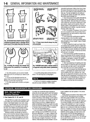 5
5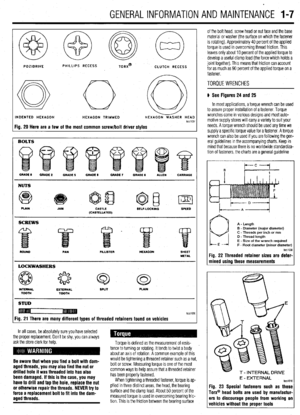 6
6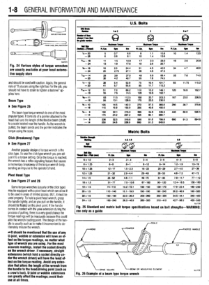 7
7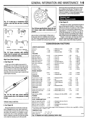 8
8 9
9 10
10 11
11 12
12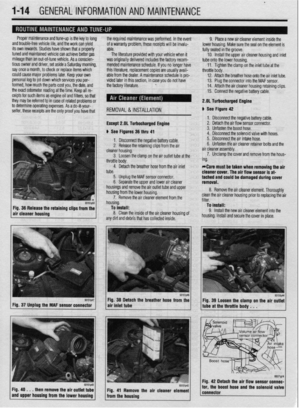 13
13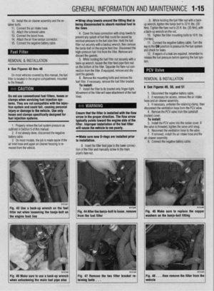 14
14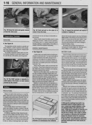 15
15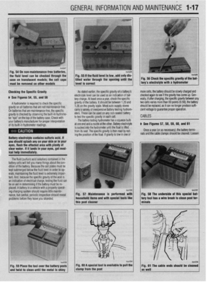 16
16 17
17 18
18 19
19 20
20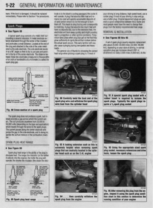 21
21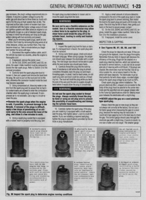 22
22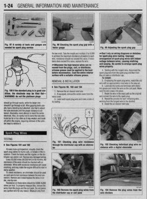 23
23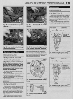 24
24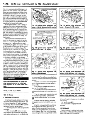 25
25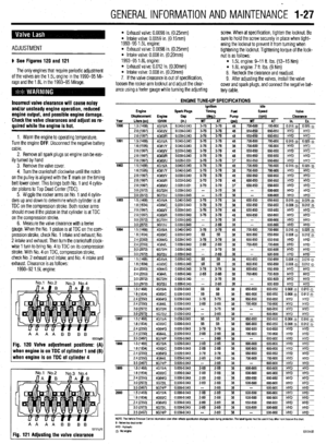 26
26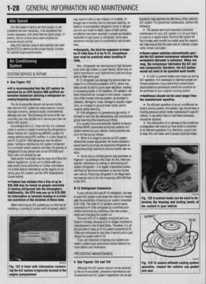 27
27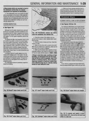 28
28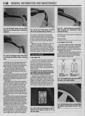 29
29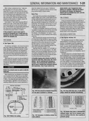 30
30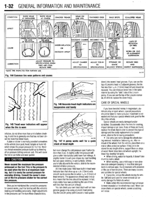 31
31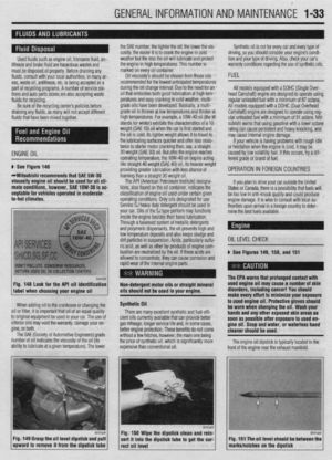 32
32 33
33 34
34 35
35 36
36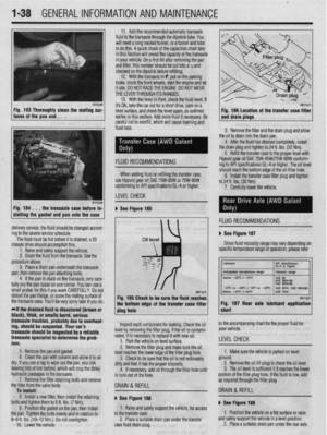 37
37 38
38 39
39 40
40 41
41 42
42 43
43 44
44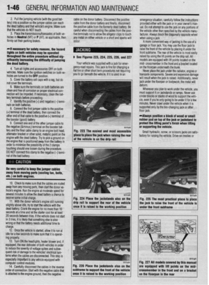 45
45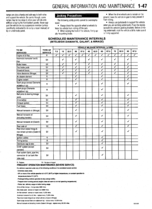 46
46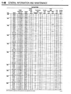 47
47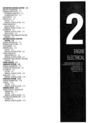 48
48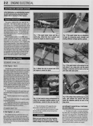 49
49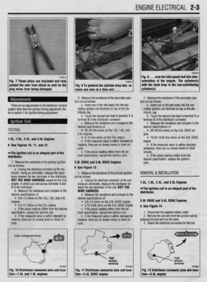 50
50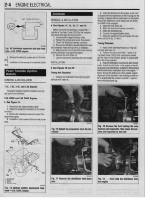 51
51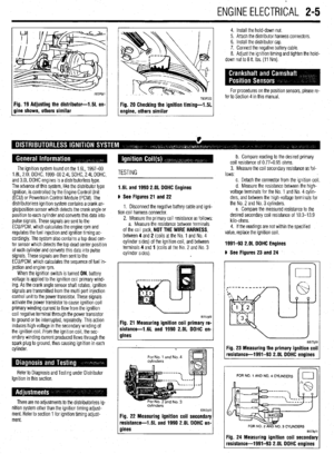 52
52 53
53 54
54 55
55 56
56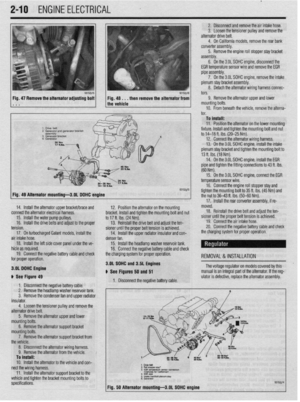 57
57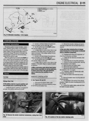 58
58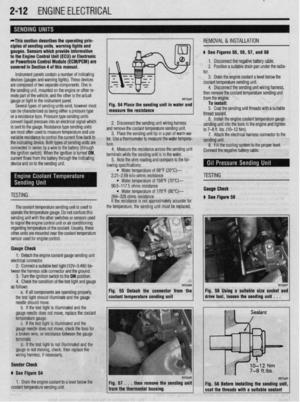 59
59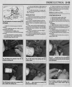 60
60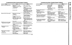 61
61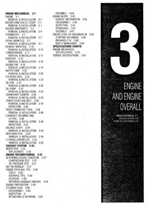 62
62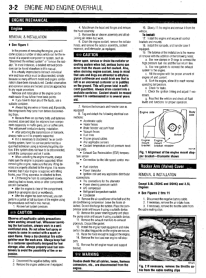 63
63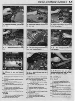 64
64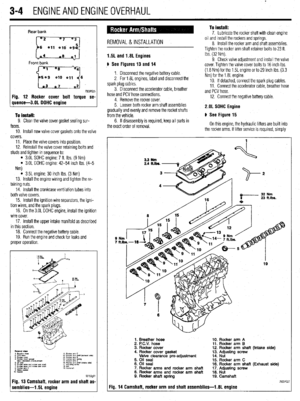 65
65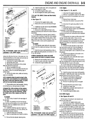 66
66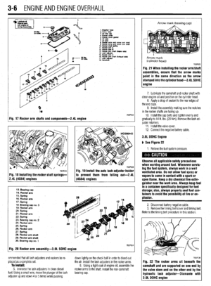 67
67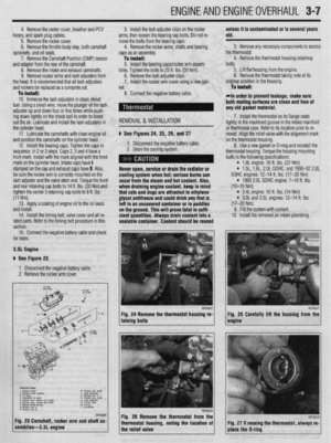 68
68 69
69 70
70 71
71 72
72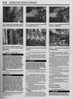 73
73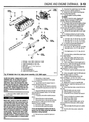 74
74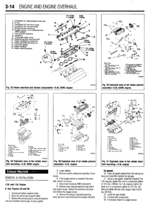 75
75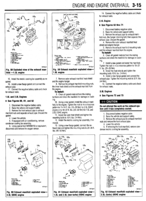 76
76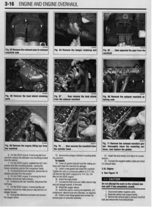 77
77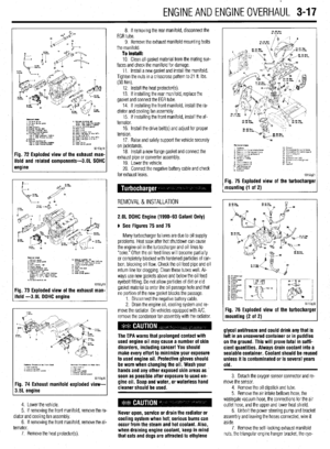 78
78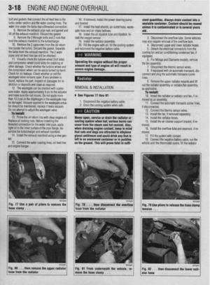 79
79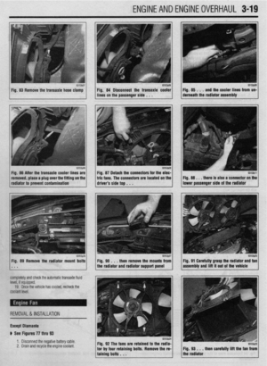 80
80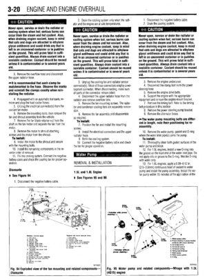 81
81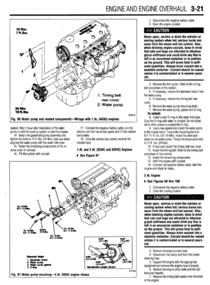 82
82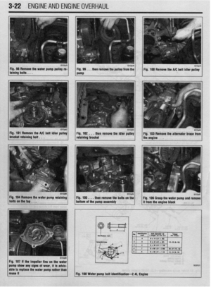 83
83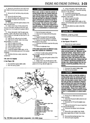 84
84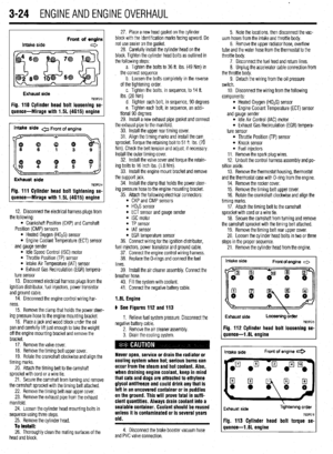 85
85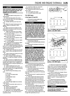 86
86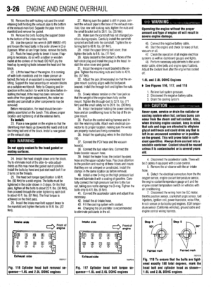 87
87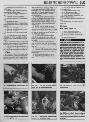 88
88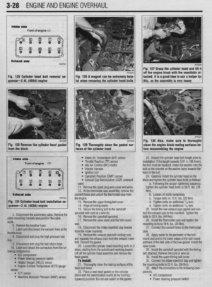 89
89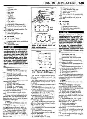 90
90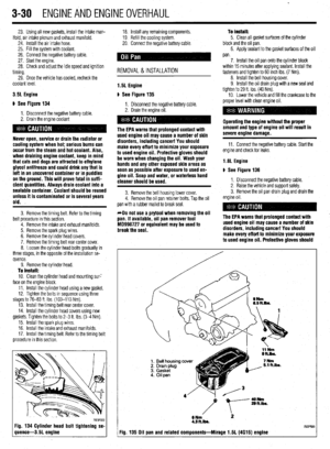 91
91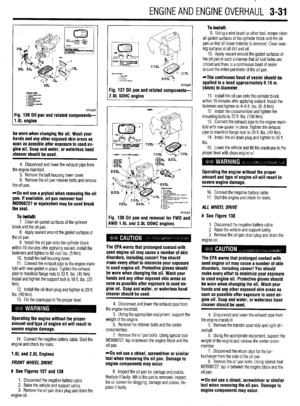 92
92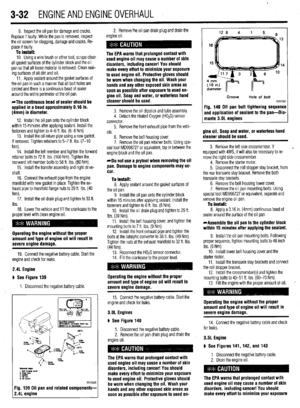 93
93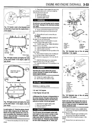 94
94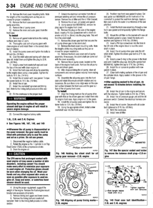 95
95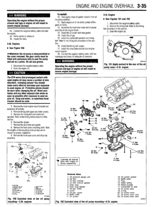 96
96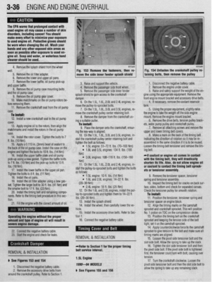 97
97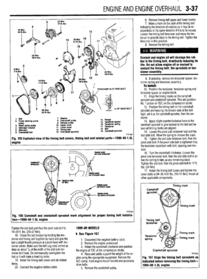 98
98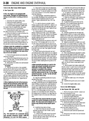 99
99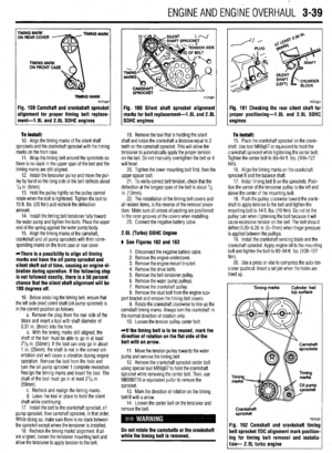 100
100 101
101 102
102 103
103 104
104 105
105 106
106 107
107 108
108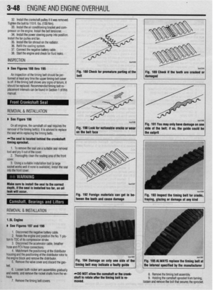 109
109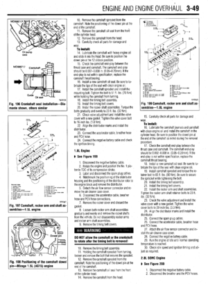 110
110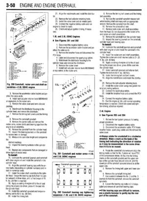 111
111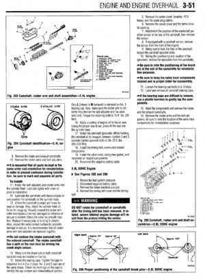 112
112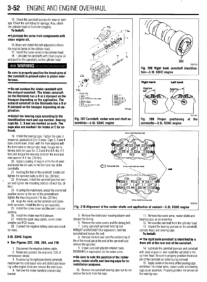 113
113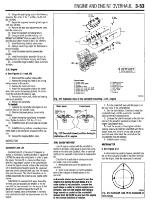 114
114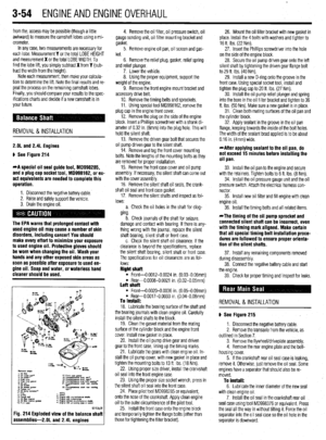 115
115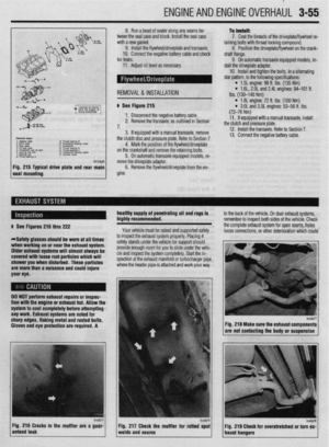 116
116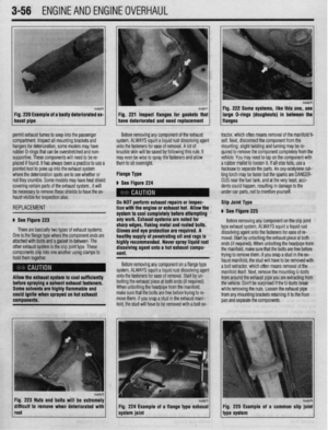 117
117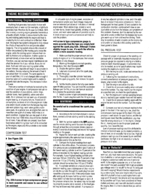 118
118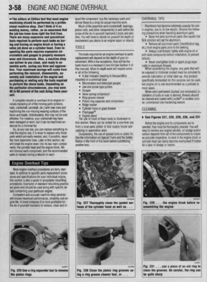 119
119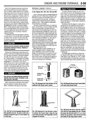 120
120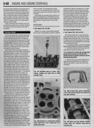 121
121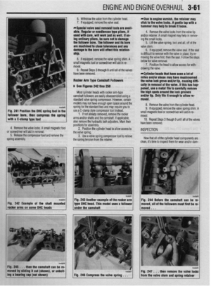 122
122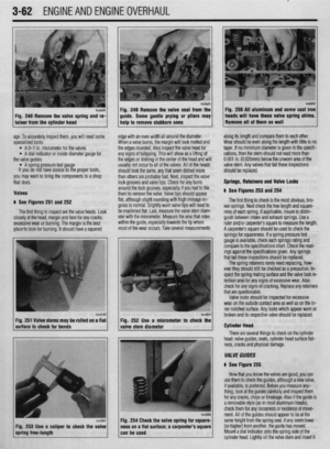 123
123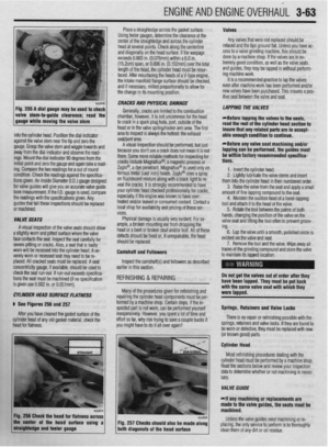 124
124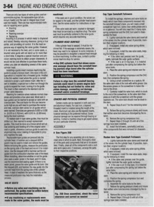 125
125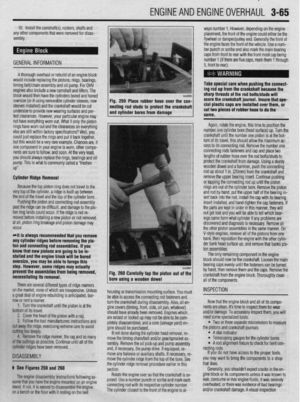 126
126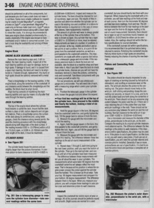 127
127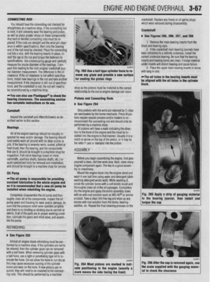 128
128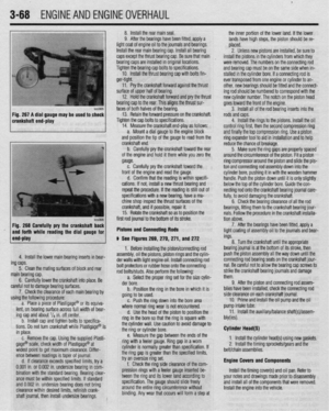 129
129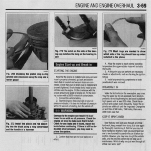 130
130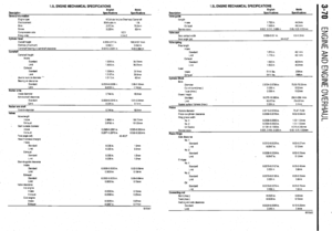 131
131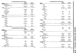 132
132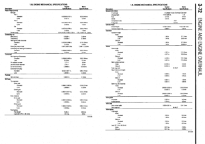 133
133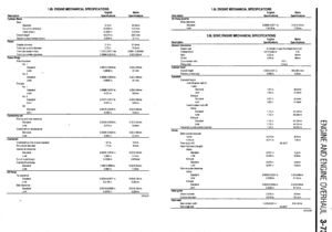 134
134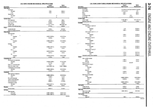 135
135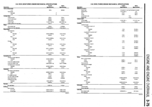 136
136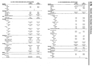 137
137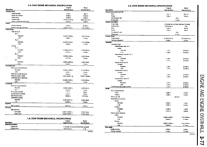 138
138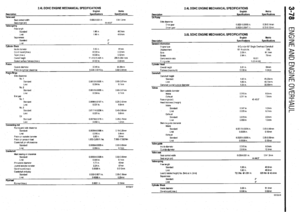 139
139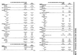 140
140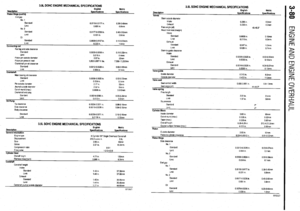 141
141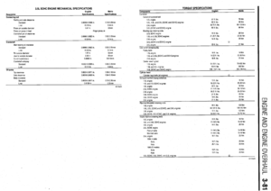 142
142 143
143 144
144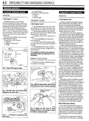 145
145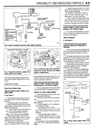 146
146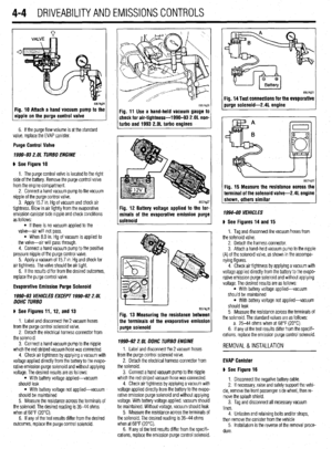 147
147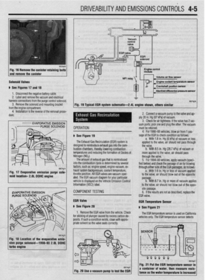 148
148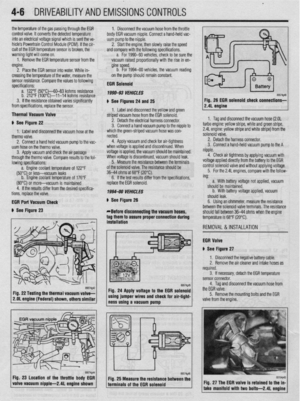 149
149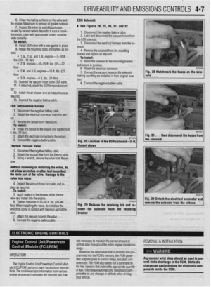 150
150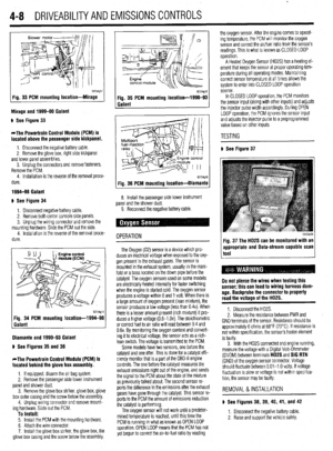 151
151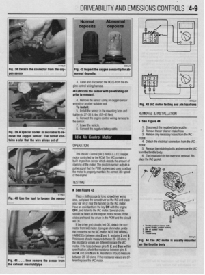 152
152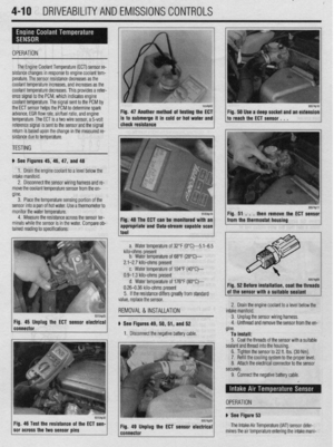 153
153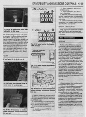 154
154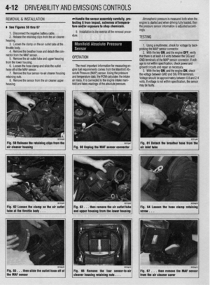 155
155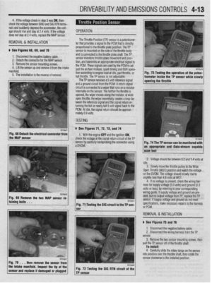 156
156 157
157 158
158 159
159 160
160 161
161 162
162 163
163 164
164 165
165 166
166 167
167 168
168 169
169 170
170 171
171 172
172 173
173 174
174 175
175 176
176 177
177 178
178 179
179 180
180 181
181 182
182 183
183 184
184 185
185 186
186 187
187 188
188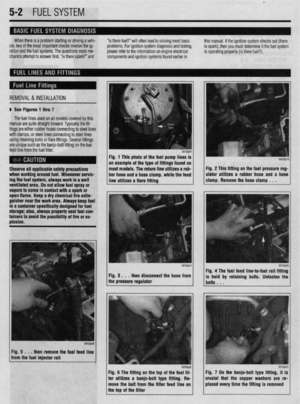 189
189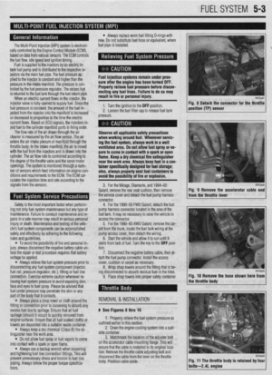 190
190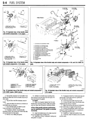 191
191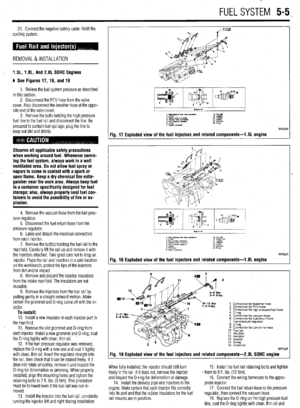 192
192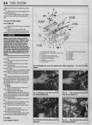 193
193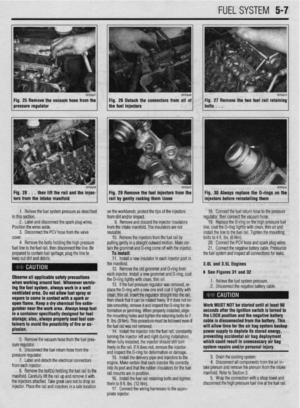 194
194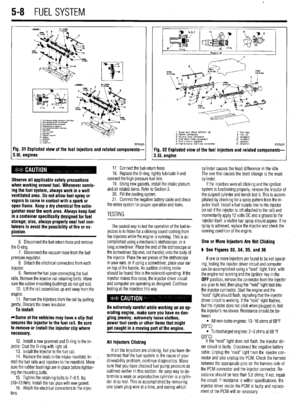 195
195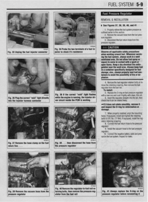 196
196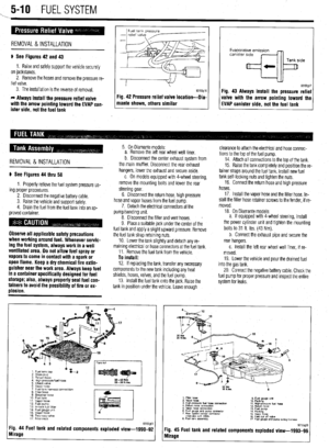 197
197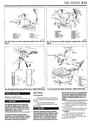 198
198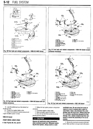 199
199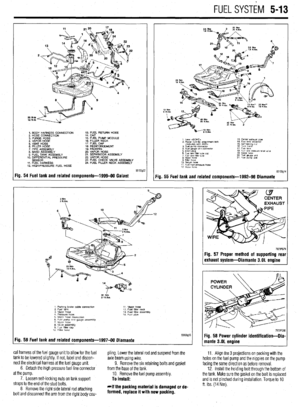 200
200 201
201 202
202 203
203 204
204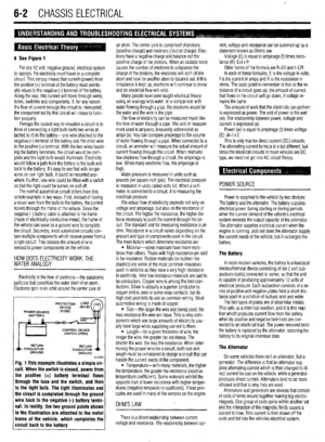 205
205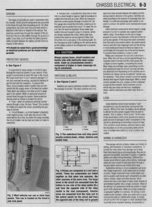 206
206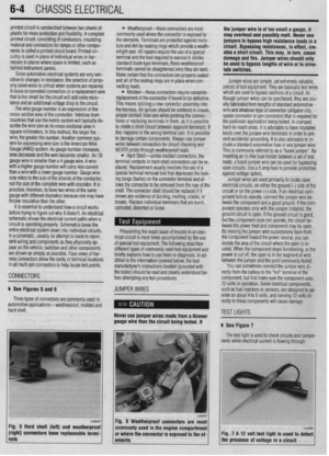 207
207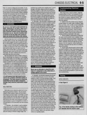 208
208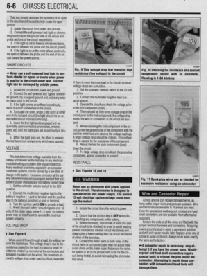 209
209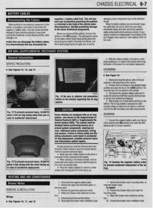 210
210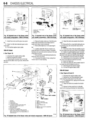 211
211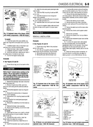 212
212 213
213 214
214 215
215 216
216 217
217 218
218 219
219 220
220 221
221 222
222 223
223 224
224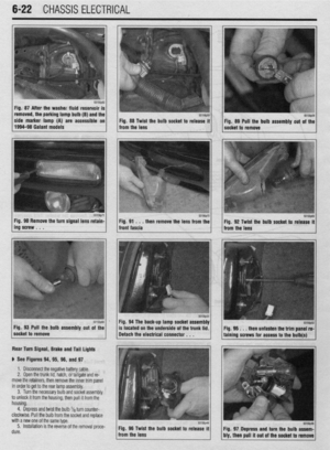 225
225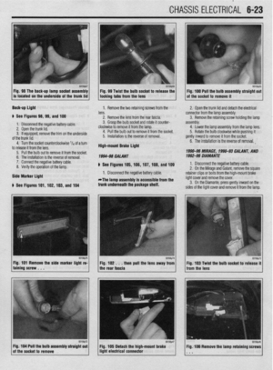 226
226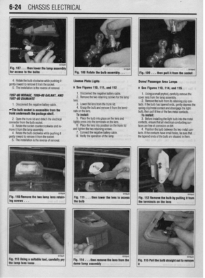 227
227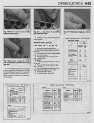 228
228 229
229 230
230 231
231 232
232 233
233 234
234 235
235 236
236 237
237 238
238 239
239 240
240 241
241 242
242 243
243 244
244 245
245 246
246 247
247 248
248 249
249 250
250 251
251 252
252 253
253 254
254 255
255 256
256 257
257 258
258 259
259 260
260 261
261 262
262 263
263 264
264 265
265 266
266 267
267 268
268 269
269 270
270 271
271 272
272 273
273 274
274 275
275 276
276 277
277 278
278 279
279 280
280 281
281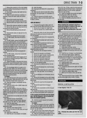 282
282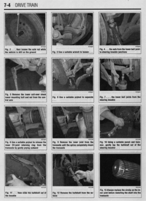 283
283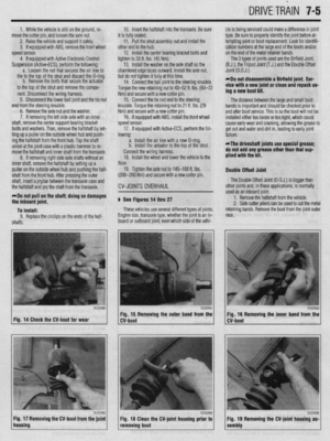 284
284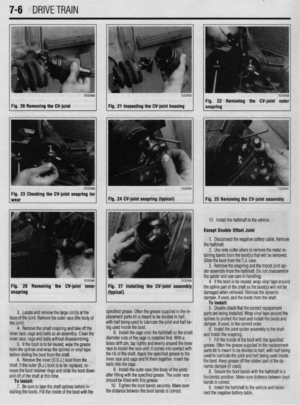 285
285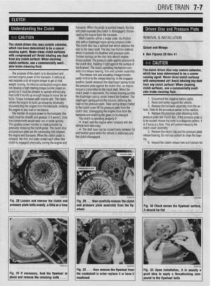 286
286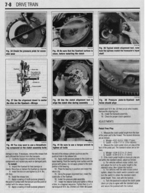 287
287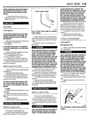 288
288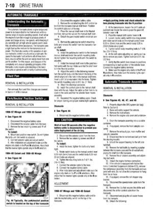 289
289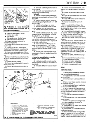 290
290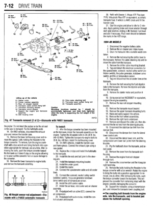 291
291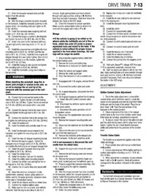 292
292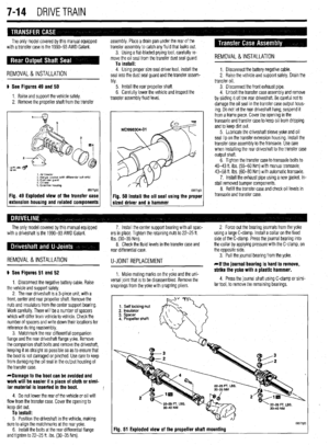 293
293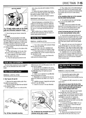 294
294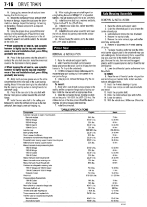 295
295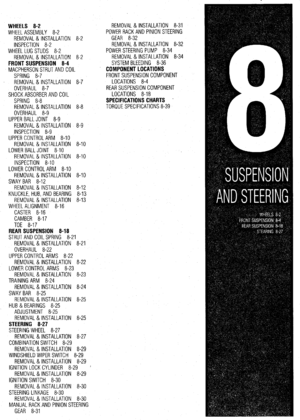 296
296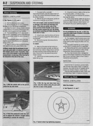 297
297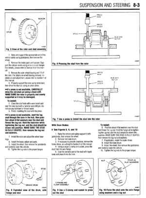 298
298 299
299 300
300 301
301 302
302 303
303 304
304 305
305 306
306 307
307 308
308 309
309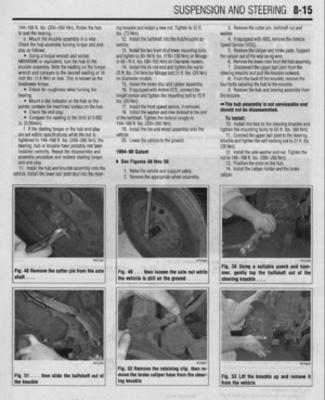 310
310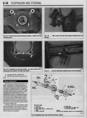 311
311 312
312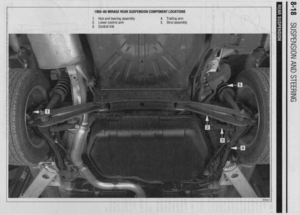 313
313 314
314 315
315 316
316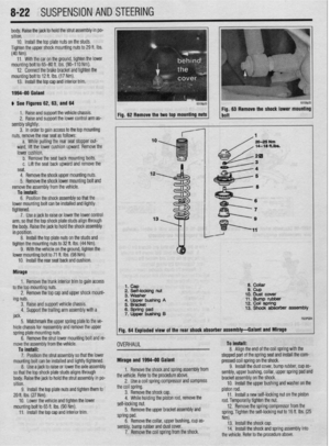 317
317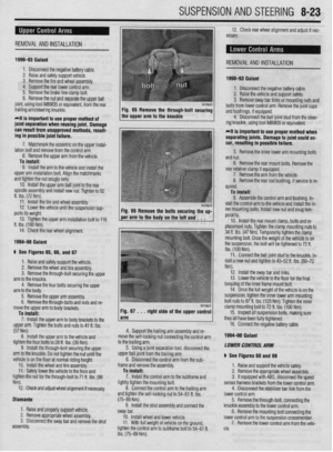 318
318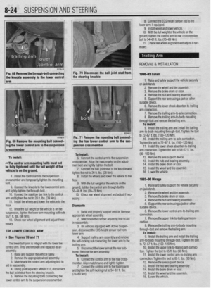 319
319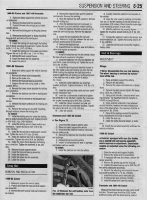 320
320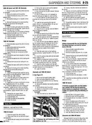 321
321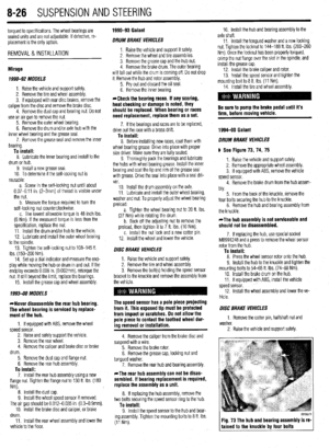 322
322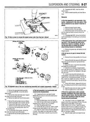 323
323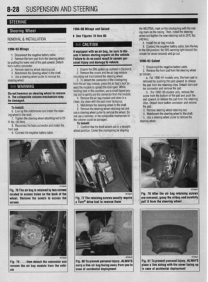 324
324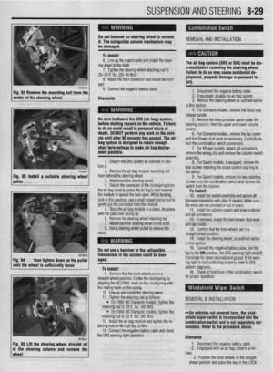 325
325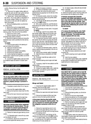 326
326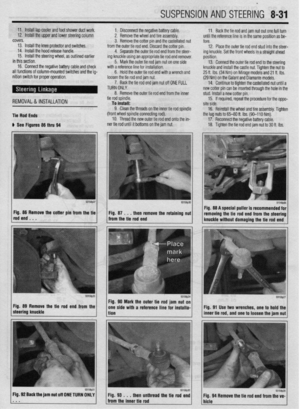 327
327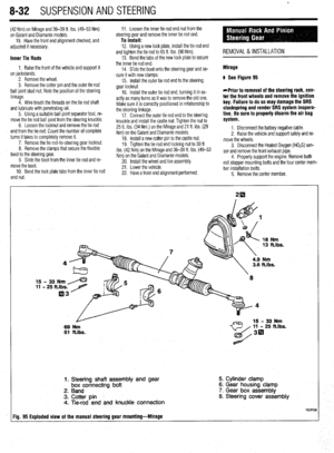 328
328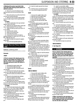 329
329 330
330 331
331 332
332 333
333 334
334 335
335 336
336 337
337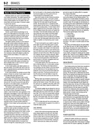 338
338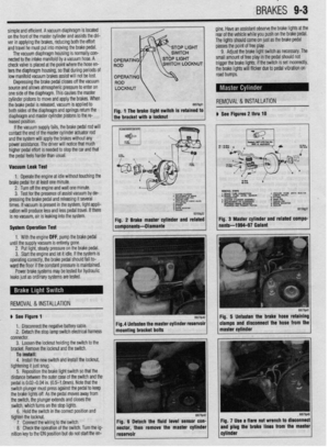 339
339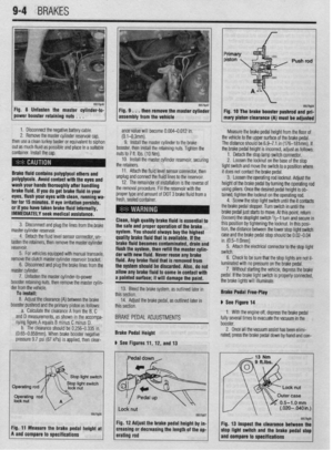 340
340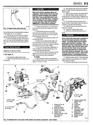 341
341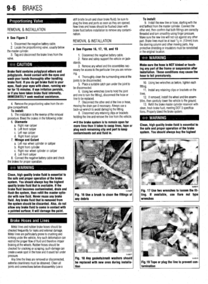 342
342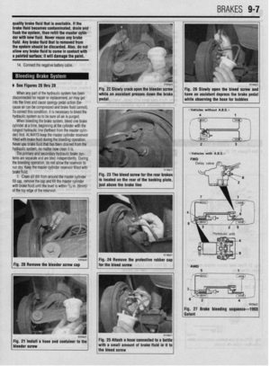 343
343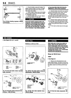 344
344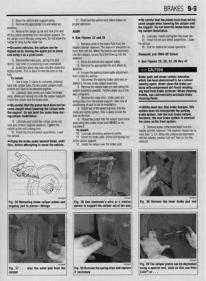 345
345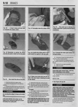 346
346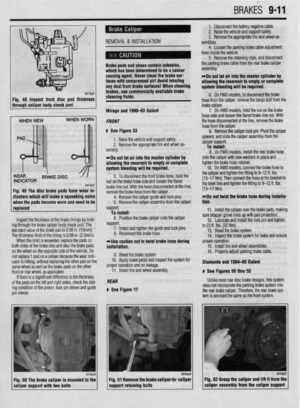 347
347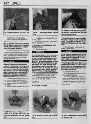 348
348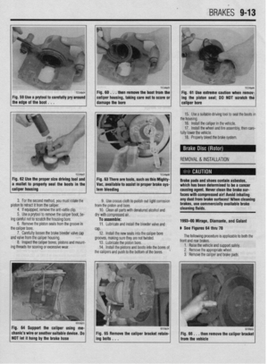 349
349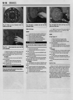 350
350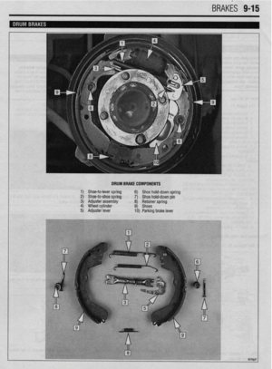 351
351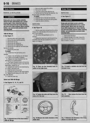 352
352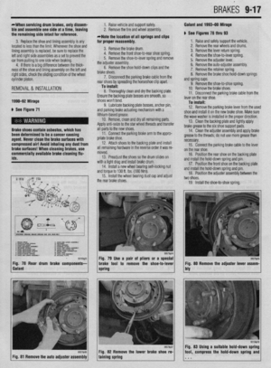 353
353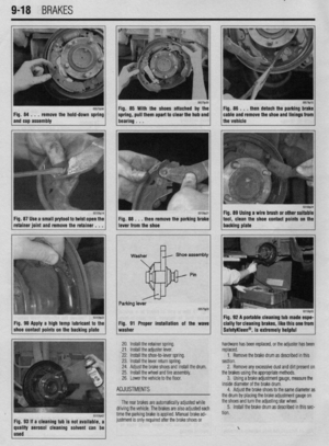 354
354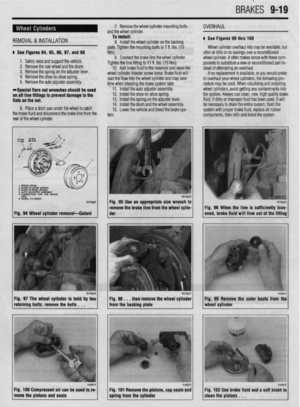 355
355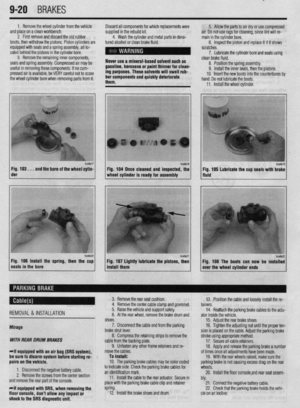 356
356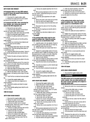 357
357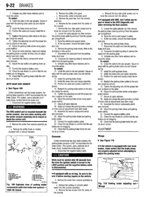 358
358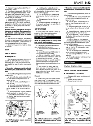 359
359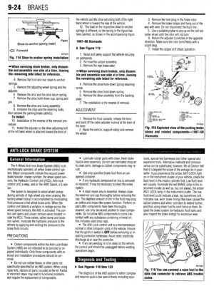 360
360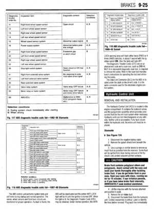 361
361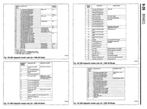 362
362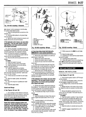 363
363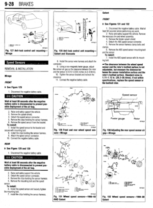 364
364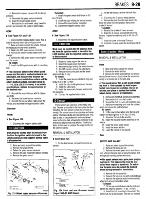 365
365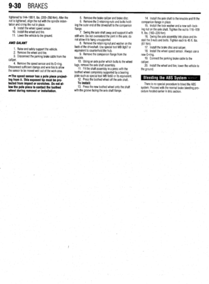 366
366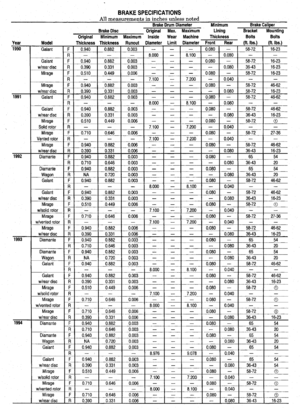 367
367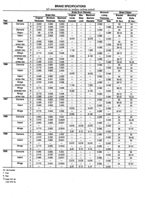 368
368 369
369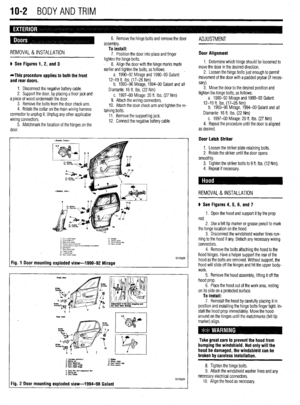 370
370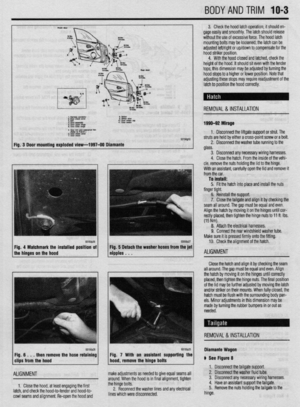 371
371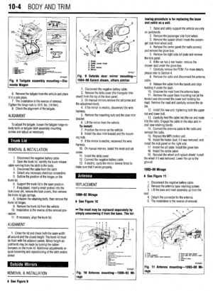 372
372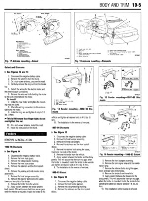 373
373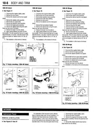 374
374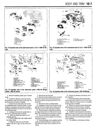 375
375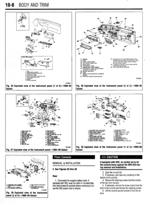 376
376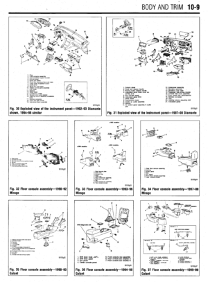 377
377 378
378 379
379 380
380 381
381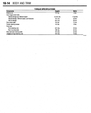 382
382 383
383 384
384 385
385 386
386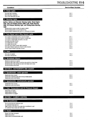 387
387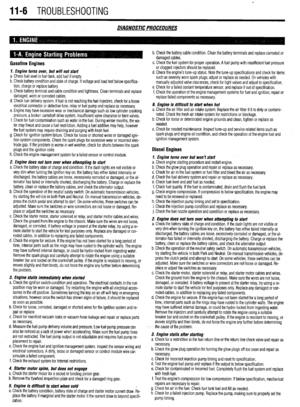 388
388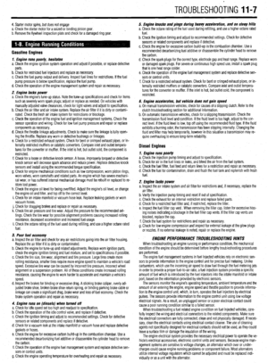 389
389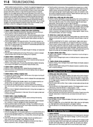 390
390 391
391 392
392 393
393 394
394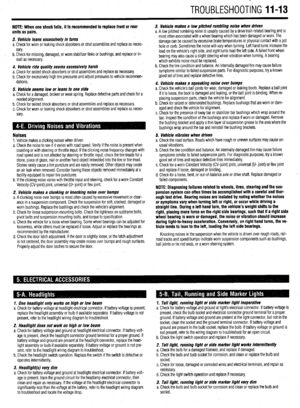 395
395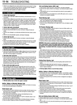 396
396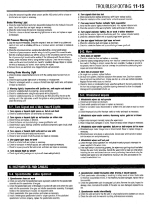 397
397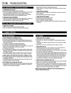 398
398 399
399 400
400 401
401 402
402 403
403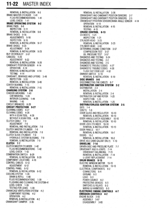 404
404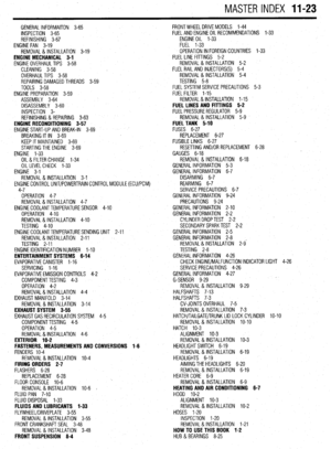 405
405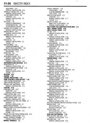 406
406 407
407