Page 329 of 408

SUSPENSION AND STEERING 8-33
*Matchmark the pinion input shaft of the
rack to the lower steering column joint for in-
stallation purposes.
6. Remove the pinch bolt holding the lower
steering column joint to the rack and pinion input
shaft.
7. Remove the cotter pins and disconnect the tie
rod ends from the steering knuckle.
8. Remove the rack and pinion steering assem-
bly and its rubber mounts from the right side of the
vehicle.
To install: 9. Align the matchmarks of the input shaft and
install the rack to the vehicle.
10. Secure the rack using the retainer clamps and
bolts. Tighten the bolts to 51 ft. Ibs. (70 Nm).
11. Tighten the steering column pinch bolt to 13
ft. Ibs. (18 Nm).
12. Install the center member.
13. Install the front exhaust pipe.
14. Connect the HO$ sensor.
15. Connect the tie rod ends to the steering
knuckles and tighten the castle nuts to 25 ft. Ibs. (34
Nm). Install new cotter pins.
16. Install the wheels and connect the negative
battery cable.
17. Have a front end alignment performed.
REMOVAL &INSTALLATION
Diamante
FRONT
*Prior to removal of the steering gear box,
center the front wheels and remove the igni-
tion key. Failure to do so may damage the
SRS clock spring and render SRS system in-
operative.
1. Disconnect the negative battery cable.
2. Disconnect the front exhaust pipe.
3. If equipped with AWD, remove the transfer
case assembly.
4. Remove the bolt holding the lower steering
column joint to the rack and pinion input shaft.
5. Remove the cotter pins and disconnect the tie
rod ends.
6. Remove the left and right frame members.
7. Remove the stabilizer bar bracket.
8. If equipped with four-wheel steering, discon-
nect the lines going to the rear pump.
9. Remove the rack and pinion steering assem-
bly and its rubber mounts. Move the rack to the right
to remove it from the crossmember.
To install: IO. Install the rack and mounting bolts. Tighten
the bolts to 51 ft. Ibs. (70 Nm). When installing the
rubber rack mounts, align the projection of the
mounting rubber with the indentation in the cross:
member. Install the pinch bolt.
11. Connect the pressure and return lines to the
rack and to the rear pump, if equipped.
12. Install the frame members and tighten the
bolts to 43-51 ft. Ibs. (60-70 Nm).
13. Connect the tie rods and install new cotter
pins. 14. Install the transfer case and front exhaust
pipe.
15. Refill the reservoir and bleed the system.
16. Have a front end alignment performed.
REAR
1. Disconnect the negative battery cable.
2. Raise the vehicle and support safely.
3. Drain the power steering fluid.
4. Remove the main muffler assembly.
5. Remove the rear shock absorber lower
mounting bolts.
6. Using the proper equipment, support the
weight of the rear differential. Remove the 2 small
crossmember brackets.
7. Remove the large self-locking crossmember
mounting nuts on the differential side.
8. Remove the oil line clamp bolts.
9. Remove the pressure tubes.
IO. Hold the tie rod ends stationary and remove
the tie rod end nuts. Remove the tie rod ends from
the trailing arms.
11. Remove the mounting bolts and remove the
rear steering gear.
To install: 12. Secure the unit to the crossmember. Move
the power cylinder piston rod over its full stroke to
determine its neutral position.
13. Align the tie rod ends with the holes in the
trailing arms and install the nuts. Adjust the length of
the tie rods with the nuts if necessary. The difference
in length between the 2 tie rod ends should not ex-
ceed 0.04 in. (1 mm). The nuts’ torque specification is
42 ft. Ibs. (58 Nm).
14. Replace the O-rings and install the pressure
tubes. Clamp in place.
15. Install the large self-locking crossmember
mounting nuts on the differential side. Tighten to
80-94 ft. Ibs. (110-130 Nm).
16. Remove the support equipment.
17. Install the 2 small crossmember brackets.
18. Install the shock mounting bolts.
19. Install the muffler assembly.
20. Refill the reservoir and bleed the system.
21. Have a front end alignment performed. _
Galant
1990-93 MODELS
1. Disconnect the negative battery cable.
2. Drain the power steering fluid.
3. Raise the vehicle and support safely.
4. Remove the bolt holding lower steering col-
umn joint to the rack and pinion input shaft.
5. Remove the transfer case, if equipped.
6. Remove the cotter pins and using the proper
tools, separate the tie rod ends from the steering
knuckle.
7. Locate the triangular brace near the stabilizer
bar brackets on the crossmember and remove both
the brace and the stabilizer bar bracket.
8. Support the center crossmember.
9. Remove the through-bolt from the round roll
stopper and remove the rear bolts from the center
crossmember.
10. Disconnect the front exhaust pipe, if
equipped with FWD.
11. Disconnect the power steering fluid pressure
pipe and return hose from the rack fittings. Plug the
fittings to prevent excess fluid leakage. 12. Lower the crossmember slightly.
13. Remove the rack and pinion steering assem-
bly and its rubber mounts. Move the rack to the right
to remove from the crossmember. Tilt the assembly
downward and remove from the left side of the vehi-
cle. Use caution to avoid damaging the boots.
To install: 14. Install the rack and install the mounting bolts. Tighten the mounting bolts to 43-58 ft. Ibs. (60-80
Nm). When installing the rubber rack mounts, align
the projection of the mounting rubber with the inden-
tation in the crossmember.
15. Connect the power steering fluid lines to the
rack.
16. Connect the exhaust pipe, if removed.
17. Raise the crossmember into position. Install
the center member mounting bolts and tighten to 72
ft. Ibs. (100 Nm). Install the roll stopper bolt and new
nut. Tighten nut to 47 ft. Ibs. (65 Nm).
18. Install the stabilizer bar brackets and brace.
19. Connect the tie rod ends and tighten nuts to
25 ft. Ibs. (34 Nm).
20. Install the transfer case, if removed. Check
and fill fluid.
21. Refill the reservoir with power steering fluid
and bleed the system.
22. Have a front end alignment performed.
1994-M MODELS
+ See Figure 96
Prior to removal of the steering gear box,
center the front wheels and remove the igni-
tion key. Failure to do so may damage the
SRS clock spring and render SRS system in-
operative.
1. Disconnect the negative battery cable.
2. Raise and properly support the vehicle.
3. Remove both front wheel assemblies.
4. Remove the bolt holding lower steering col-
umn joint to the rack and pinion input shaft.
5. Remove the stabilizer bar.
6. Remove the cotter pins, and using joint sepa-
rator MB991 113 or equivalent, disconnect the tie rod
ends from the steering knuckle.
7. On vehicles equipped with Electronic Control
Power steering (EPS), detach the wiring harness from
the solenoid connector.
8. Locate the two triangular braces near the
crossmember and remove both.
9. Support the center crossmember. Remove the
through-bolt from the front round roll stopper and re-
move the bolts securing the center crossmember.
10. Remove the center crossmember. ,
Il. Properly support the engine and remove the
rear roll stopper through-bolt.
12. Disconnect the power steering fluid pressure
pipe and return hose from the rack fittings. Plug the
fittings to prevent excessive fluid leakage.
13. Remove the clamp bolts and the two bolts se-
curing the rack assembly to the chassis.
14. Remove the rack and pinion steering assem-
bly and its rubber mounts.
*When removing the rack and pinion as-
sembly, tilt the assembly to the vehicle side
of the compression lower arm and remove
from the left side of the vehicle.
Page 330 of 408

8-34 SUSPENSION AND STEERING'
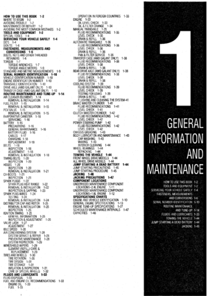
Fig. 96 Exploded view of the power steering gear removal procedure- -Galant 43 Nm*
7 18 Nm
24-33 Nm
18-24 ttlbs.
15 Nm . 11 ftlbs. 6
57 Nm
42 ft.lbs.
\1- 69 Nm
51 ft.lbs. 24-33 Nm
18-24
ft.1 bs.
’ 78-86 Nm
58-65 ft.lbs.
69-78
Nm 51-58 ftlbs.
1. Joint assembly and gear box con-
necting bolt
2. Cotter pin
3. Connection for tie rod end and
knuckle
4. Stay
5. Center member assembly
6. Clamp
7. Bott
I 8. Gear box assembly
Caution
The fasteners marked * should be temporarily
tightened before they are finally tightened once
the total weight of the engine has been placed
on the vehicle
body.
7923PGAl
To install:
15. Center the rack assembly and insert the pin-
ion into the steering column shaft.
16. Install the rack and mounting bolts. Tighten
the mounting bolts to 51 ft. Ibs. (69 Nm).
17. Install the pinch bolt and tighten the bolt to
13 ft. Ibs. (18 Nm).
18. Connect the power steering fluid lines to the
rack and tighten the pressure hose fitting to 11 ft. Ibs.
(15 Nm). Secure the return hose with the clamp.
19. Raise the engine into position.
20. Install the rear roll stopper through-bolt and I
tighten to 32 ft. Ibs. (43 Nm).
21. Raise the crossmember into position. Install
_ the center member mounting bolts; tighten the front
bolts to 58-65 ft. Ibs. (78-88 Nm) and the rear bolt
to 51-58 ft. Ibs. (69-78 Nm).
22. Install the front roll stopper bolt and tighten
the nut to 32 ft. Ibs. (43 Nm).
23. Install the two triangular braces and tighten
the mounting bolts to 50-56 ft. Ibs. (69-78 Nm). 24. Install the stabilizer bar.
25. Connect the tie rod ends and tighten the nuts
to 20 ft. Ibs. (27 Nm).
26. On vehicles equipped with EPS, connect the
wiring harness to the solenoid connector.
27. Install the wheel assemblies and lower the
vehicle.
28. Refill the reservoir with power steering fluid
and bleed the system.
29. Have a front end alignment performed.
Mirage
1990-92 MODELS
I. Disconnect the battery negative cable.
2. Raise the vehicle and support safely.
3. Remove the pinch bolt holding the lower
steering column joint to the rack and pinion input
shaft. 4. Remove the cotter pins and disconnect the tie
rod ends from the steering’knuckle.
5. Disconnect the power steering fluid pressure
pipe and return hose from the rack fittings.
6. Remove the rack and pinion steering assem-
bly and its rubber mounts.
To install:
7. Install the steering gear into the vehicle and
secure using the retainer clamps and bolts.
8. Connect the power steering fluid lines to the
rack fittings.
9. Install the stabilizer bar and rear transaxle
bracket.
10. Connect the tie rod ends to the steering
knuckles.
ll= Connect the negative battery cable.
12. Refill the reservoir and bleed the system.
13. Have a front end alignment performed.
Page 331 of 408

SUSPENSION AND STEERING 8-35
1. Steering shaft assembly and gear
box connecting bolt
2. Band
3. Cotter pin
4. Tie-rod end and knuckle connection
5. Return tube connection 6. Pressure tube connection
7. Cylinder clamp
8. Gear housing clamp
9. Gear box assembly 10. Steering cover assembly
7923PGAl FiD= 97 Exploded view of the power steering gear assembly-Mirage
1993-90 MODELS To install:
) See Figure 97
*Prior to removal of the steering gear box,
center the front wheels and remove the igni-
tion key. Failure to do so may damage the
SRS clockspring and render SRS system in-
operative.
,mr;iin thepower steering system.
2. Disconnect the battery negative cable. Raise
the vehicle and support safely.
3. Disconnect the Heated Oxygen (HOPS) sen-
sor and remove the front exhaust pipe.
4. Properly support the engine.
5. Remove both roll stopper mounting bolts and
the four center member installation bolts. Remove the
center member.
6. Remove the center member. 11. Align the matchmarks of the input shaft and
install the rack to the vehicle.
12. Secure the rack using the retainer clamps and
bolts. Tighten the bolts to 51 ft. Ibs. (70 Nm).
13. Tighten the steering column pinch bolt to 13
ft. Ibs. (18 Nm).
14. Using new O-rings, connect the power steer-
ing fluid lines to the rack fittings.
15. Install the center member.
16. Install the front exhaust pipe.
17. Connect the H02S sensor.
18. Connect the tie rod ends to the steering
knuckles and tighten the castle nuts to 25 ft. Ibs. (34
Nm). Install new cotter pins.
19. Install the wheels and connect the negative
battery cable.
20. Refill ‘the reservoir and bleed the system.
21. Have a front end alignment performed.
stallation purposes. -
7. Remove the pinch bolt holding the lower REMOVALANDINSTALLATION
steering column joint to the rack and pinion input
shaft.
8. Remove the cotter pins and disconnect the tie
rod ends from the steering knuckle.
9. Disconnect the power steering fluid pressure
pipe and return hose from the rack fittings.
IO. Remove the rack and pinion steering assem-
bly and its rubber mounts from the right side of the
vehicle. Mirage
1, Drain the power steering system as follows:
a. Disconnect the return hose at the reservoir
and place into a suitable container.
b. Disable the ignition system. While crank-
ing the engine, turn the wheels several times, un-
til system has been drained. 2. Disconnect the battery negative cable.
3. Remove the pressure switch connector from
the side of the pump.
4. If the alternator is located under the oil pump,
cover it with a shop towel to protect it from oil.
5. Disconnect the pressure line.
6. Remove the steering pump drive belt and the
water pump pulley drive belt.
7. Remove the water pump pulley.
8. Remove the bolts that secure the oil pump,
then remove the pump from its bracket.
To install: 9. Install the power steering pump and tighten
the mounting bolts to specifications.
IO. Install the water pump pulley and tighten the
mounting bolts 14 ft. Ibs. (19 Nm).
11. Install and adjust the drive belts.
12. Replace the O-rings and connect the pressure
line. Connect the pressure line so the notch in the fit-
ting aligns and contacts the pump’s guide bracket.
Tighten the nut that secures the pressure line to 13 ft.
Ibs. (18 Nm).
13. Connect the return line.
14. Attach the pressure switch connector.
15. Refill the reservoir and bleed the system.
1990-93 Galant
FRONT
1. Disconnect the battery negative cable.
2. Remove the pressure switch connector from
the side of the pump.
Page 332 of 408

8-36 SUSPENSION AND STEERING
4 SL Engine>
<1.8L Engine>
Removal steps
1. Drive belt
7. BoIt
2. Pressure switch connector
8. Bolt
3. Suction hose
9. Oil pump
4. Pressure hose
10. Oil pump brace
2 Elrg
11. Oil pumo bracket stay
12. Oil pump bracket
93158gal
Exploded view of the power steering pump-Mirage
3. If the alternator is located under the oil pump,
cover it with a shop towel to protect it from oil.
4. Disconnect the return fluid line.
5. Remove the reservoir cap and allow the re-
turn line to drain the fluid from the reservoir. If the
fluid is contaminated, disconnect the ignition high
tension cable and crank the engine several times to
drain the fluid from the gearbox.
6. Disconnect the pressure line.
7. Remove the pump drive belt.
8. Remove the pump mounting bolts and re-
move the pump from the engine.
To install: 9. Install the pump, wrap the belt around the
pulley and loosely tighten the mounting bolts.
10. Replace the O-rings and connect the pressure
line. Connect the pressure line so the notch in the fit-
ting aligns and contacts the pump’s guide bracket.
1 I. Connect the return line. Attach the pressure
switch connector.
12. Adjust the belt tension and tighten the adjust-
ing bolts to 25-33 ft. Ibs. (35-45 Nm).
13. Refill the reservoir and bleed the system.
REAR
1. Raise the vehicle and support safely.
2. Drain the differential gear oil.
3. Matchmark and remove the rear driveshaft.
4. Remove the rear halfshafts.
5. Remove the center exhaust pipe and muffler
assembly, as required.
35-45 Nm 9-14 Nm
14-Z Nm 25-33 ft.lbs.
9 7-10 klbs.
6/
2 g-lb Nm
7-10 ft.lbs.
Exploded view of the front power steering pump-1990-93 Galant
Page 333 of 408

SUSPENSION AND STEERING 8-37
19-28 Nm
14-20 klbs.
/
12-18 Nm
9- 13 ft.lbs.
2rd
,
1. Feed tube
2. O-ring
3. Rear oil pump
4. O-ring
93158ga:
Exploded view of the rear power steering pump-1990-93 Galant
6. Disconnect the pressure and suction hoses
from the fittings on the pump.
7. The large mounting bolts that hold the differ-
ential carrier support plate to the underbody may use
self-locking nuts. Before removing them, support the
rear axle assembly in the middle with a transaxle
jack. Remove the nuts, then remove the support
plate(s) and the square dynamic damper from the rear
of the carrier.
8. Lower the differential carrier
and remove from
the vehicle.
9. Remove the pump retaining bolt and remove
the pump from the rear differential assembly.
To install: IO. Install the pump and tighten the mounting
bolt to 14-20 ft. Ibs. (19-28 Nm).
11. Raise the rear differential carrier into position
and install support member bolts. Replace all self-
locking nuts. Tighten all mounting nuts and bolts as
follows:
l Upper support plate to carrier bolts: 72-87
ft. Ibs. (100-120 Nm)
l Support member/dynamic damper to car-
rier bolts: 58-72 ft. Ibs. (80-100 Nm)
l Differential support member mounting bolt
nuts: 80-94 ft. Ibs. (110-130 Nm)
12. Connect the pressure and suction lines to the
pump.
13. Install new circlips on both rear driveshafts
and install. I
14.
Install the propeller shaft and tighten the
mounting hardware to 22-25 ft. Ibs. (30-35 Nm).
15. Install the center exhaust pipe and muffler.
1
16. Lower the vehicle. With the vehicle level, fill
the rear differential.
17. Fill the power steering system and properly
bleed.
1994-00 Galant
2.4L ENGINE
1. Disconnect the battery negative cable.
2. Loosen and remove the power steering pump
drive belt.
3. Remove the pressure switch connector from
the side of the pump.
*If the alternator is located under the oil
pump, cover it with a shop towel to protect it
frqm oil.
4. Disconnect the return fluid line. Remove the
reservoir cap and allow the return line to drain the
fluid from the reservoir. If the fluid is contaminated,
disconnect the ignition high tension cable and crank
the engine several times to drain the fluid from the
gearbox.
5. Disconnect the pressure line.
6. Unbolt and remove the pump from the
mounting bracket.
To install: 7. Install the pump, wrap the belt around the
pulley and lightly tighten the mounting bolts.
8. Replace the O-rings and connect the pressure
line. Connect the pressure line so the notch in the fit-
ting aligns and contacts the pump’s guide bracket.
Tighten the fitting to 13 ft. Ibs. (18 Nm).
9. Connect the return line and secure with the
clamp.
IO. Attach the pressure switch connector.
<2.4L ENGINE> 12 N-m 12 N-m
<3.OL ENGINE>
32 ft-lb
1. DRIVE BELT
2. PRESSURE SWITCH CONNECTOR
3. SUCTION HOSE
; i’;;‘;;RE HOSE 7. BOLT
8. ~O~~~E;TEER’NG PUMP
9. OIL PUMP
10. OIL PUMP BRACKET
6. BOLT
93158gal
Exploded view of the power steering pump-1994-00 Galant with 2.4L engine
Page 334 of 408

- 8-38 SUSPENSION AND STEERING
11. Adjust the power steering belt for proper ten-
sion and tighten the adjusting bolts.
12. Reconnect the negative battery cable.
13. Refill the reservoir and bleed the system.
3. Of EIJGINE
1. Disconnect the battery negative cable. 2. Disconnect the return fluid line. Remove the
reservoir cap and allow the return line to drain the
fluid from the reservoir. If the fluid is contaminated,
disconnect the ignition high tension cable and crank
the engine several times to drain the fluid from the
gear box.
3. Remove the power steering pump drive belt.
4. Remove the pressure switch connector from
the side of the pump.
5. If the alternator is located under the oil pump,
cover it with a shop towel to protect it from oil.
6. Disconnect the high pressure hose and the
return hose from the pump.
7. Remove the pump drive belt and unbolt the
pump from its bracket and remove the pump.
To install: 8. Install the pump, *rap the belt around the
pulley and tighten the bolts that secure the pump to
17 ft. Ibs. (24 Nm).
9. Replace the O-rings and connect the high
pressure hose. Connect the pressure line so the
notch in the fitting aligns and contacts the pump’s
guide bracket. Tighten the mounting nut with lock-
washer to 17 ft. Ibs. (24 Nm).
IO. Using a new hose clamp, connect the return
line.
11. Attach the pressure switch connector.
12. Adjust the belt tension and tighten the
adjust- ing bolts.
13. Refill the reservoir and bleed the system.
Diamante *
FRONT
. 1. Disconnect the battery negative cable. 2. Disconnect the return fluid line. Remove the
reservoir cap and allow the return line to drain the
fluid from the reservoir. If the fluid is contaminated,
disconnect the ignition high tension cable and crank
the engine several times to drain the fluid from the
gearbox.
3. Remove the power steering pump drive belt.
4. Remove the pressure switch connector from
the side of the pump.
5. If the alternator is located under the oil pump,
cover it with a shop towel to protect it from oil.
6. Disconnect the high pressure hose and the
return hose from the pump.
7. Remove the pump drive belt and unbolt the
pump from its bracket and remove the pump.
To install: 8. Install the pump, wrap the belt around the
pulley and tighten the bolts that secure the pump to
17 ft. Ibs. (24 Nm).
9. Replace the O-rings and connect the high
pressure hose. Connect the pressure line so the
notch in the fitting aligns and contacts the pump’s
guide bracket. Tighten the mounting nut with lock-
washer to 17 ft. Ibs. (24 Nm).
10. Using a new hose clamp, connect the return
line.
Il. Attach the pressure switch connector.
12. Adjust the belt tension and tighten the adjust-
ing bolts.
13. Refill the reservoir and bleed the system.
REAR
1. Disconnect the negative battery cable.
2. Drain the power steering fluid.
3. Remove the rear power steering pump heat
protector, located on the engine side of the differen-
tial on the transaxle.
4. Disconnect the pressure line from the pump.
5. Disconnect the suction hose from the pump.
6. Remove the mounting bolts and remove the
pump from the transaxle.
44
33
REMOVAL STEPS
5. POWER STEERING PUMP
BRACKET STAY
6. OIL PUMP 1. DRIVE-BELT
2. SUCTION HOSE I ’ 3. PRESSURE HOSE
4. PRESSURE SWITCH
CONNECTOR
Exploded view of the power steering pump-Diamante
. 93158ga5
7. The installation is the reverse of the removal
procedure. Tighten the mounting bolts to 17 ft. Ibs.
(24 Nm).
8. Refill the reservoir and bleed the system.
Extreme caution should be taken when test-
ing the rear steering pump. Ensure that the
vehicle is supported safely and that all com-
ponents are torqued to specification prior be
testing.
. SYSTEM BLEEDING
,Front
1. Raise the vehicle and support safely.
2. Manually turn the pump pulley a few times.
3. Turn the steering wheel all the way to the left
and to the right 5 or 6 times.
4. Disconnect the ignition high tension cable
and, while operating the starter motor intermittently,
turn the steering wheel all the way to the letI and right
5-6 times for 15-20 seconds. During bleeding,
make sure the fluid in the reservoir never falls below
the lower position of the filter. If bleeding is at-
tempted with the engine running, the air will be ab-
sorbed in the fluid. Bleed only while cranking.
5. Connect ignition high tension cable, start en-
gine and allow to idle.
6. Turn the steering wheel left and right until
there are no air bubbles in the reservoir. Confirm that
the fluid is not milky and the level is up to the speci-
fied position on the gauge. Confirm that there is very
little change in the fluid level when the steering wheel
is turned. If the fluid level changes more than 0.2 in.
(5mm), the air has not been completely bled. Repeat
the process.
Rear
.
1. Bleed the front steering system.
2. Start the engine and let it idle.
3. Loosen the bleeder screw on the left side of the
control valve and install special tool MB991230 to
the bleeder.
4. Turn the steering wheel all the way to the left,
then immediately turn it halfway back. Confirm that
air has discharged with the fluid.
5. Repeat Step 4 two or three times as required,
to remove all air from the rear system. Stop the en-
gine.
6. Loosen the power cylinder (rear steering gear)
bleeder screw about I/* turn and install the same
special tool with the rotation prevention metal fixtures
to prevent the bleeder from opening more.
7. Start the engine and run to 50 mph to circulate
the fluid.
8. Maintain a speed of 20 mph and turn the steer-
ing wheel back and forth. Air should be discharged ,
through the tube of the special tool and into the oil
reservoir.
9. Repeat until all air is removed from the power
cylinder.
Page 335 of 408

Hub and beari")
SUSPENSION AND STEERliG 8-39
Components
Air bag retaining screws TORQUE SPECIFICATIONS English
48 inch Ibs. Metric
5Nm
Front Suspension
Damper fork-to-lateral arm (1994-98 Galant)
Hub and bearing assembly-to-steering knuckle bolts
Lower ball joint-to-steering knuckle
I
All
Lower control arm
Diamante, 1990-93 Galant, and 1999-00 Galant
Rear mount clamp retaining bolts
Rear mount clamp retaining nuts
Frame mount through bolt
1994-98 Galant
Lateral arm rear bolt
Compression arm retaining bolt
Mirage
Front mount
Rear mount
Shock absorber and coil spring-to-body nuts
1994-98 Galant
Shock absorber and coil spring-to-damper fork through bolt
1994-98 Galant
Shock absorber and coil spring-to-damper fork pinch bolt
Mirage
Strut-to-body mounting bolts/nuts
Diamante, 1990-93 Galant, and 1999-00 Galant
Mirage
Strut-to-steering knuckle mounting bolts
Diamante, 1990-93 Galant, and 1999-00 Galant
Mirage
Sway bar mount retaining bolts
1994-00 Galant
Diamante
Mirage
Sway bar links-to-damper fork (1994-98 Galant)
Tie-rod end-to-steering knuckle nuts
Mirage
Galant and Diamante
Tie rod end jam nut
Mirage
. Galant and Diamante
Upper ball joint-to-steering knuckle nut (1994-98 galant)
Upper control arm-to-shaft through bolts (1994-98 Galant)
Upper control arm-to-body nuts (1994-98 Galant)
Wheel hub retaining nut
Manual rack and pinion
Steering shaft upper pinch bolt
Rack retainer bolts
Power rack and pinion
Front
Inner tie rod-to-rack and pinion
Steering shaft upper pinch bolt
Diamante I
Except Diamante
Rack retainer bolts
Diamante
1990-93 Galant
1994-00 Galant . 64 ft. Ibs.
65 ft. Ibs.
43-52 ft. Ibs.
72-87 ft. Ibs.
29 ft. Ibs.
75-90 ft. Ibs.
71-85 ft Ibs.
60 ft. Ibs.
65 ft. tbs.
78 ft. Ibs.
32 ft. Ibs.
65 ft. Ibs.
76 ft. Ibs.
33
ft. tbs. 29 ft. Ibs.
70-76 ft. Ibs.
80-94 ft. Ibs.
28 ft. Ibs.
32 ft. Ibs.
16 ft. Ibs.
29 ft. Ibs
25 ft. Ibs.
21 ft. Ibs.
30 ft. tbs.
36-39 ft. Ibs.
20 ft. Ibs.
41 ft. Ibs.
62 ft. Ibs.
145-188 ft. Ibs.
13 ft. Ibs.
51 ft. lbs.
65 ft. Ibs.
21 fta Ibs.
13 ft. Ibs.
51 ft. Ibs.
43-58 ft. Ibs
51 ft. Ibs. 88 Nm
88 Nm
60-72 Nm
100-120 Nm
40 Nm
102-l 22 Nm
98-l 18 Nm
83 Nm
90Nm
108 Nm
44 Nm
88 Nm
103 Nm
45 Nm
40 Nm
90-105 Nm
110-130 Nm
39 Nm
44 Nm
22 Nm
40 Nm
34 Nm
29 Nm
42 Nm
49-53 Nm
28 Nm
57 Nm
86 Nm
200-260 Nm
18Nm
70 Nm
88 Nm
29 Nm
l8Nm
70Nm -
60-80 Nm
70 Nm
70 Nm
93158cOl
Mirage 51 ft. Ibs.
Page 336 of 408

8-40 SUSPENSION AND STEERING
Components
Rear TORQUE SPECIFICATIONS English
Metric
Rack retainer bolts
Control arm-to-trailing arm nut Diamante
Power steering pump
Hose fittings
Front pump retaining bolts
Mirage
1990-93 Galant
1994-00 Galant
Diamante
Rear pump retaining bolts
1990-93 Galant
Diamante
Rear suspension
Axle retaining nut
1990-92 Mirage
1993-00 Mirage
1990-93 Galant w/drum brakes
1990-93 Disc brakes
Lower control arm
Diamante 51 ft. Ibs
13 ft. Ibs,
14 ft. Ibs.
25-33 ft. tbs.
17 ft. tbs.
17 ft. Ibs.
25-33 ft. Ibs.
17 ft. Ibs.
108-145 ft. Ibs.
130 ft. Ibs.
20 ft. Ibs.
145-188 ft. Ibs.
54-61 ft. Ibs. 54-61 ft. Ibs.
72 ft. Ibs.
43-52 ft. Ibs.
33 ft. Ibs.
29 ft. Ibs.
32 ft. Ibs.
20 ft. Ibs.
71 ft. Ibs.
28 ft. Ibs.
33 ft. tbs.
72-87 ft. Ibs.
72-87 ft. Ibs.
99414 ft. Ibs.
101-116 ft. Ibs.
52 ft. Ibs.
71 ft. Ibs.
116 ft. Ibs.
28 ft. Ibs.
54-61 ft. Ibs.
54-65 ft. Ibs.
25-33 ft. Ibs.
33 ft. Ibs.
29 ft Ibs.
65-80 ft. Ibs. Control arm-to-crossmember
Galant
Rear mount
Ball joint-to-knuckle
Strut
Upper mounting nuts
Diamante
1990-93 Galant
1994-00 Galant
Mirage
Lower strut mounting bolt
All models
Sway bar mount retaining bolts
Diamante and 1994-00 Galant
1990-93 Galant
Trailing arm-to-body through bolt
1990-93 Galant
1993-00 Mirage
1994-00 Galant and 1997-00 Diamante
1992-96 Diamante
Upper ball joint retaining nut
1990-93 Galant
1994-98 Galan t
Upper control arm retaining bolts
1990-93 Galant
1994-98 Galant
Diamante
Wheel hub mounting bolts
Steering wheel retaining nut
1990-93 Galant
1994-00 Diamante
All other models 70 Nm
18 Nm
19 Nm
35-45 Nm
24 Nm
24 Nm
35-45 Nm
24 Nm
150-200 Nm
180 Nm
27 Nm
200-260 Nm
75-89 Nm
75-89 Nm
100 Nm
60-72 Nm
45 Nm
40 Nm
44 Nm
28 Nm
98 Nm
39 Nm
45 Nm
100-120 Nm
100-120 Nm
137-157 Nm
140-160 Nm
72Nm *
98 Nm
160 Nm
39 Nm
75-89 Nm
74-88 Nm
35-45 Nm
45 Nm
40 Nm
90-l IO Nm
93158co2
Wheel lug nuts
 1
1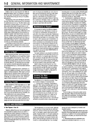 2
2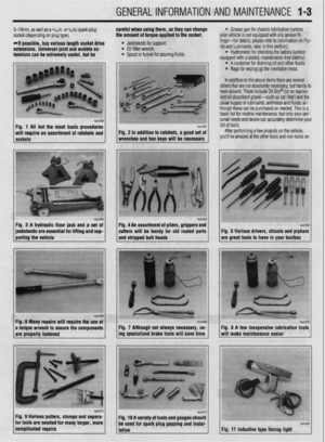 3
3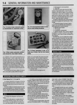 4
4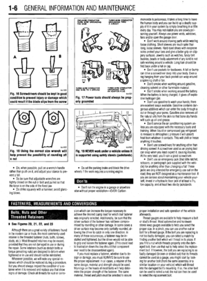 5
5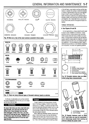 6
6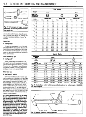 7
7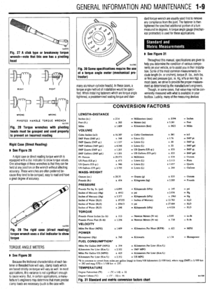 8
8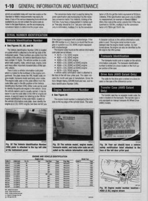 9
9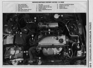 10
10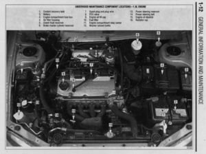 11
11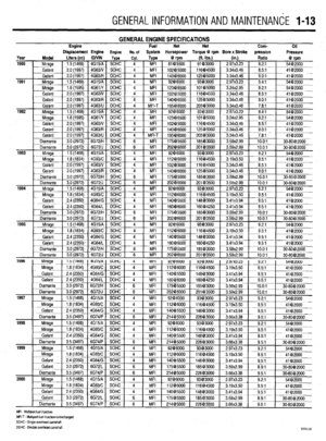 12
12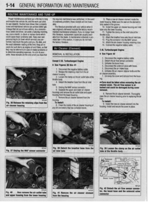 13
13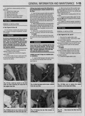 14
14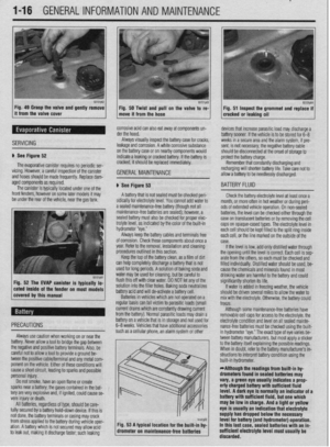 15
15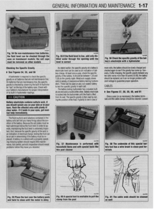 16
16 17
17 18
18 19
19 20
20 21
21 22
22 23
23 24
24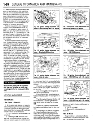 25
25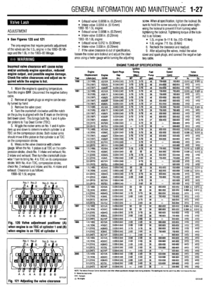 26
26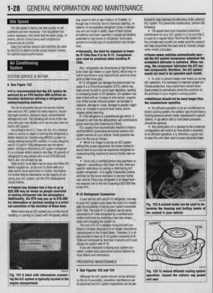 27
27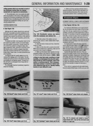 28
28 29
29 30
30 31
31 32
32 33
33 34
34 35
35 36
36 37
37 38
38 39
39 40
40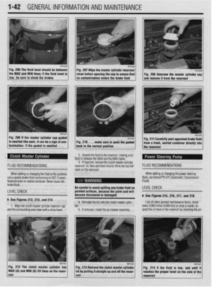 41
41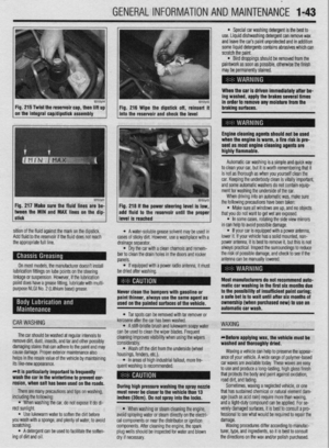 42
42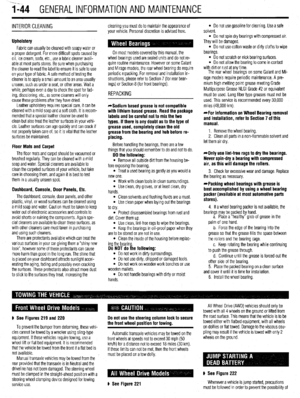 43
43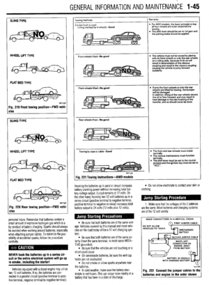 44
44 45
45 46
46 47
47 48
48 49
49 50
50 51
51 52
52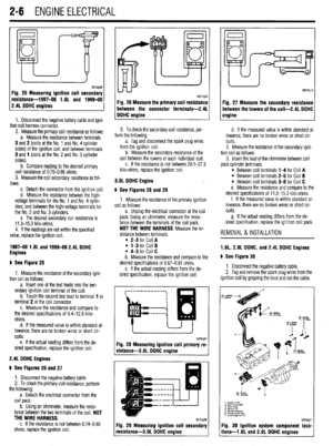 53
53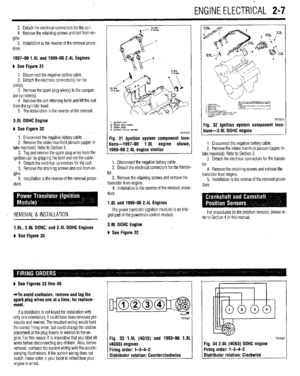 54
54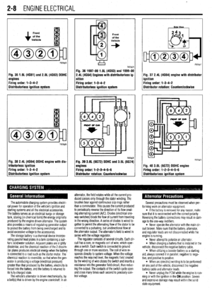 55
55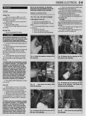 56
56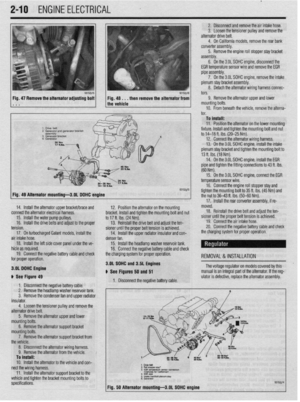 57
57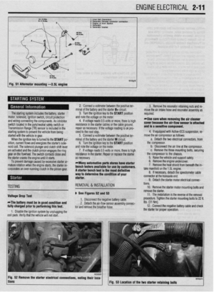 58
58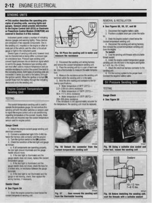 59
59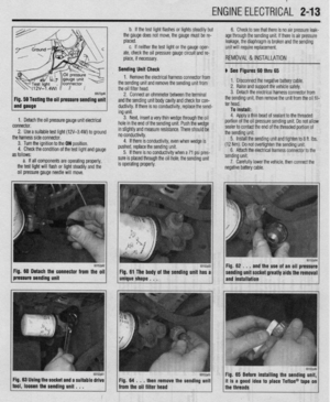 60
60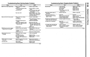 61
61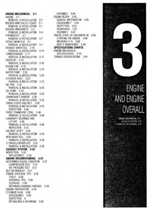 62
62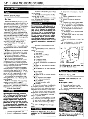 63
63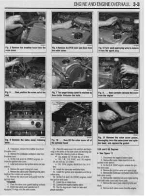 64
64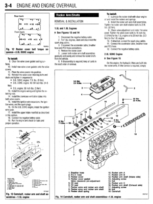 65
65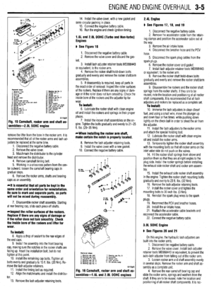 66
66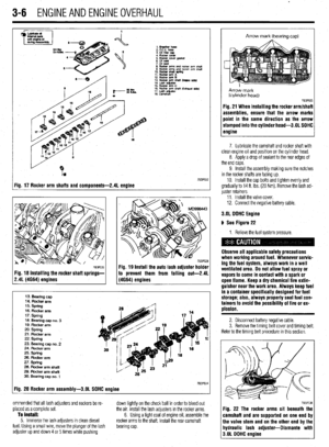 67
67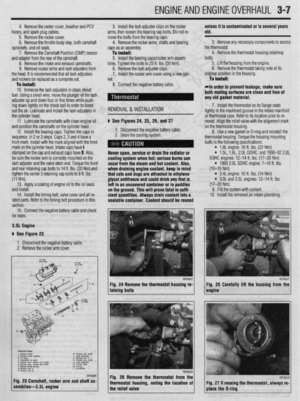 68
68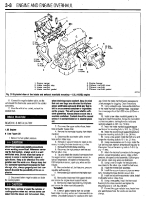 69
69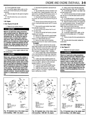 70
70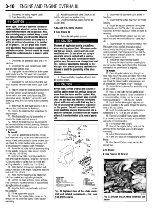 71
71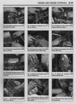 72
72 73
73 74
74 75
75 76
76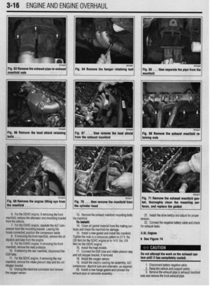 77
77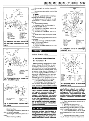 78
78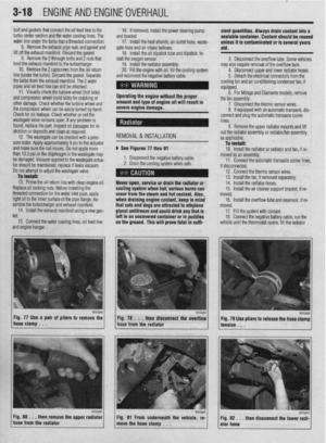 79
79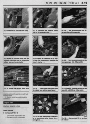 80
80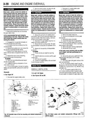 81
81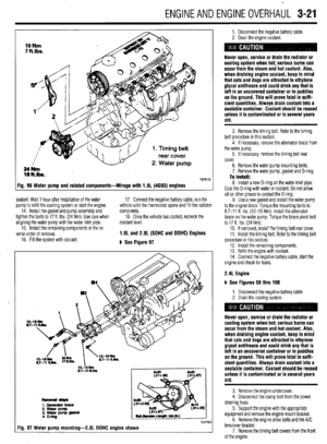 82
82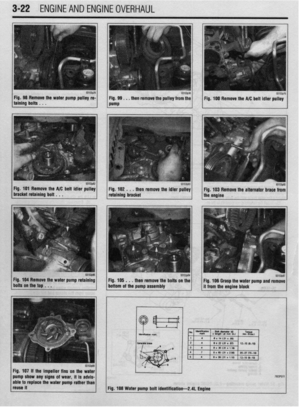 83
83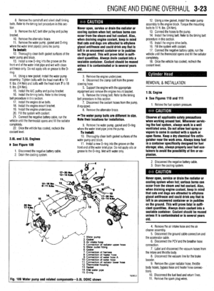 84
84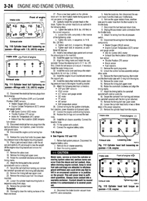 85
85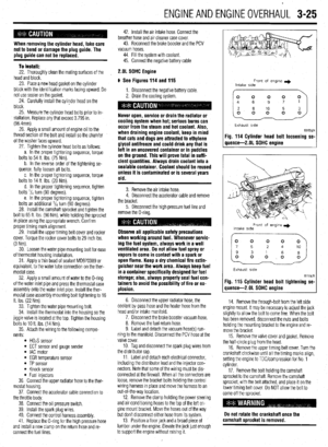 86
86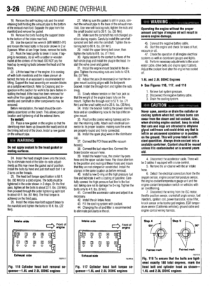 87
87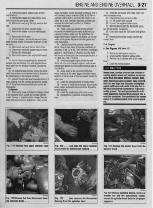 88
88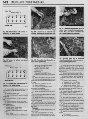 89
89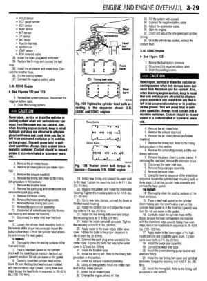 90
90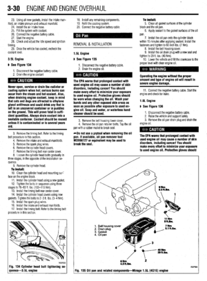 91
91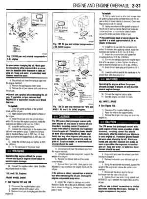 92
92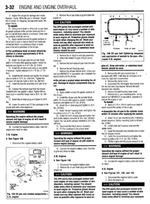 93
93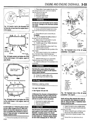 94
94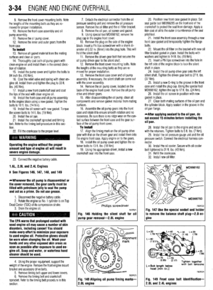 95
95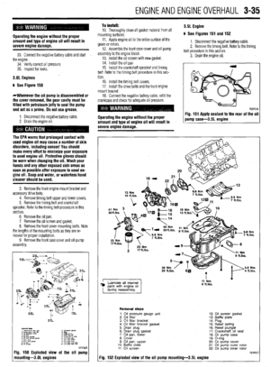 96
96 97
97 98
98 99
99 100
100 101
101 102
102 103
103 104
104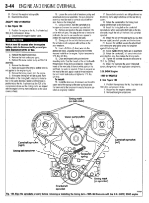 105
105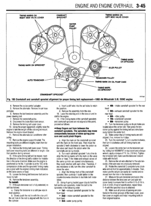 106
106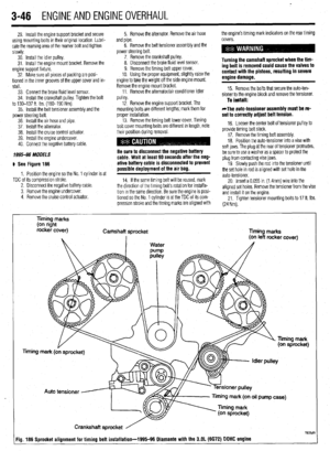 107
107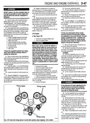 108
108 109
109 110
110 111
111 112
112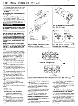 113
113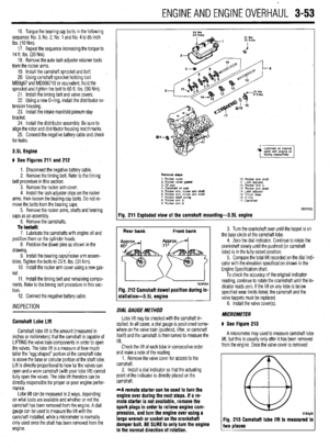 114
114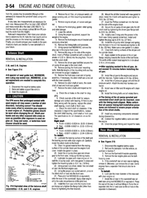 115
115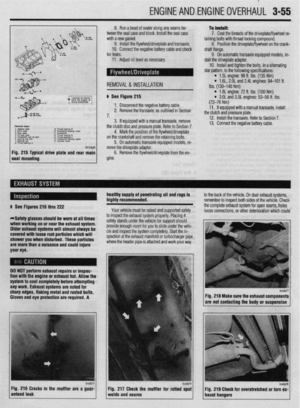 116
116 117
117 118
118 119
119 120
120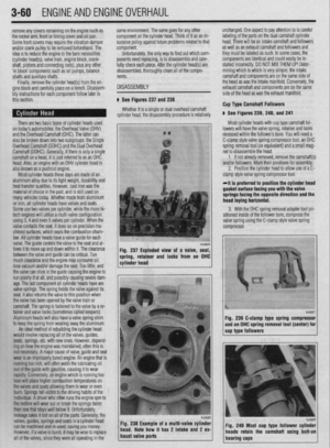 121
121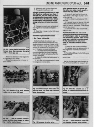 122
122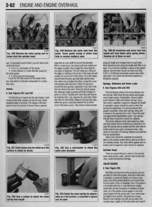 123
123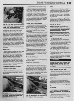 124
124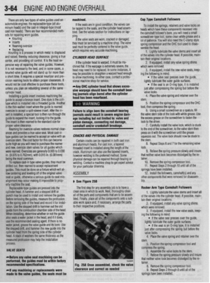 125
125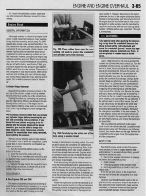 126
126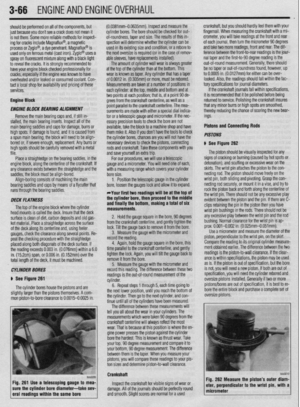 127
127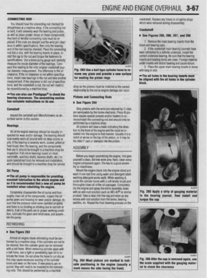 128
128 129
129 130
130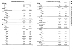 131
131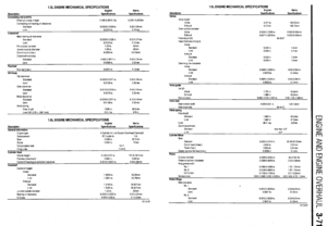 132
132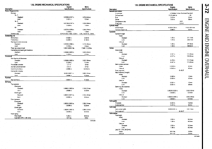 133
133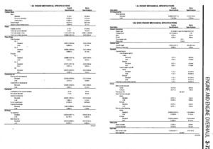 134
134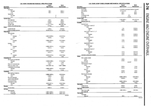 135
135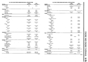 136
136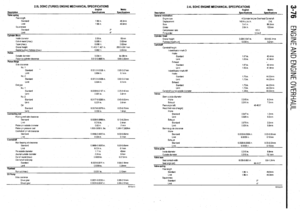 137
137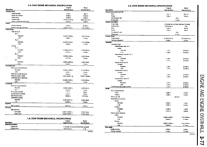 138
138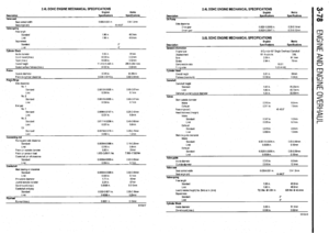 139
139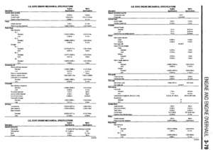 140
140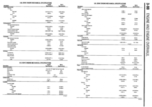 141
141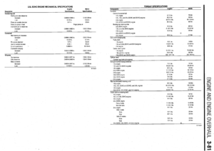 142
142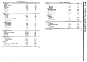 143
143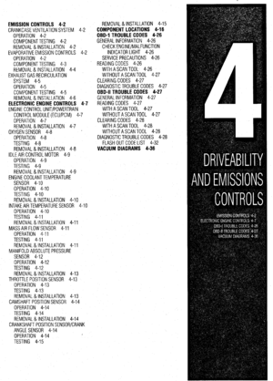 144
144 145
145 146
146 147
147 148
148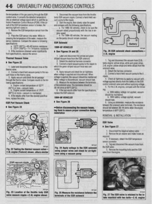 149
149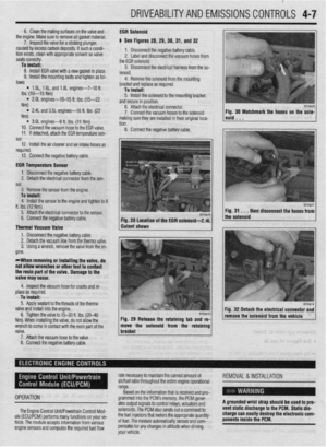 150
150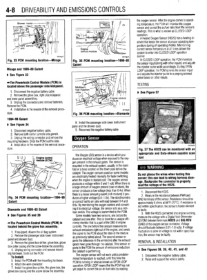 151
151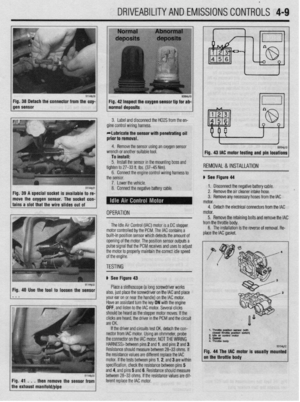 152
152 153
153 154
154 155
155 156
156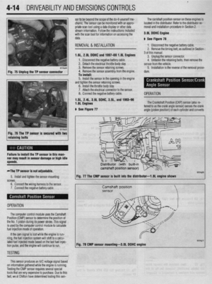 157
157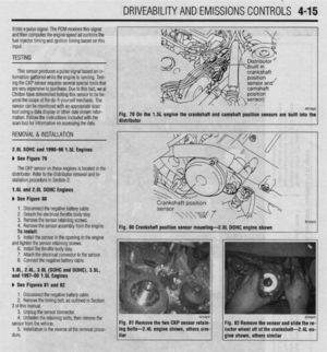 158
158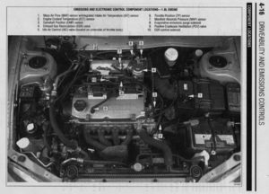 159
159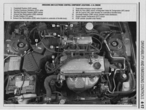 160
160 161
161 162
162 163
163 164
164 165
165 166
166 167
167 168
168 169
169 170
170 171
171 172
172 173
173 174
174 175
175 176
176 177
177 178
178 179
179 180
180 181
181 182
182 183
183 184
184 185
185 186
186 187
187 188
188 189
189 190
190 191
191 192
192 193
193 194
194 195
195 196
196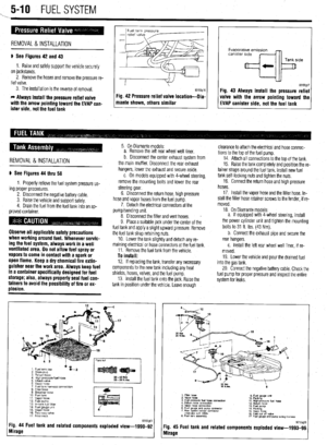 197
197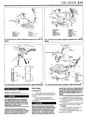 198
198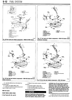 199
199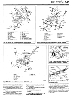 200
200 201
201 202
202 203
203 204
204 205
205 206
206 207
207 208
208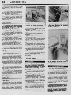 209
209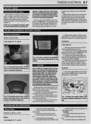 210
210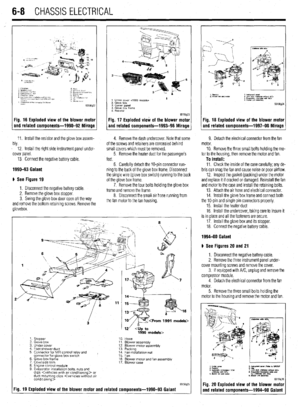 211
211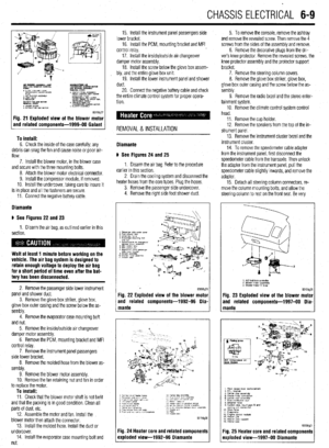 212
212 213
213 214
214 215
215 216
216 217
217 218
218 219
219 220
220 221
221 222
222 223
223 224
224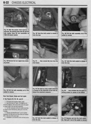 225
225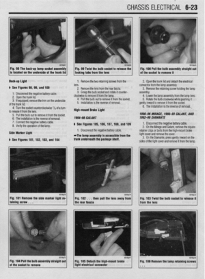 226
226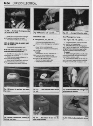 227
227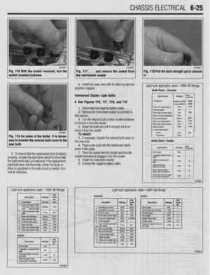 228
228 229
229 230
230 231
231 232
232 233
233 234
234 235
235 236
236 237
237 238
238 239
239 240
240 241
241 242
242 243
243 244
244 245
245 246
246 247
247 248
248 249
249 250
250 251
251 252
252 253
253 254
254 255
255 256
256 257
257 258
258 259
259 260
260 261
261 262
262 263
263 264
264 265
265 266
266 267
267 268
268 269
269 270
270 271
271 272
272 273
273 274
274 275
275 276
276 277
277 278
278 279
279 280
280 281
281 282
282 283
283 284
284 285
285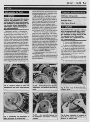 286
286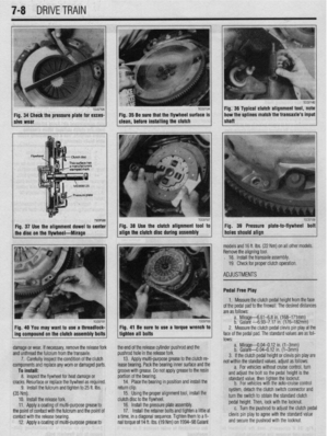 287
287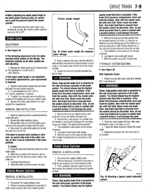 288
288 289
289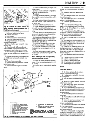 290
290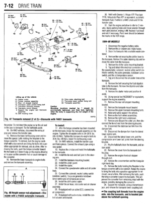 291
291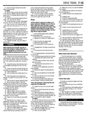 292
292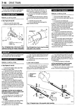 293
293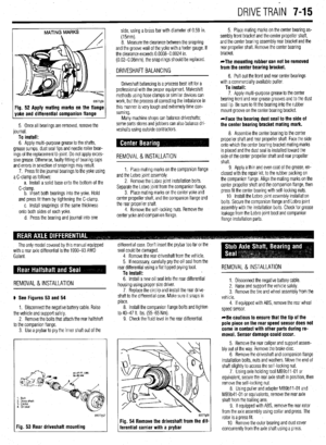 294
294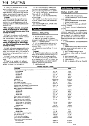 295
295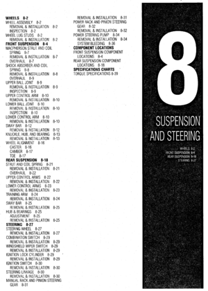 296
296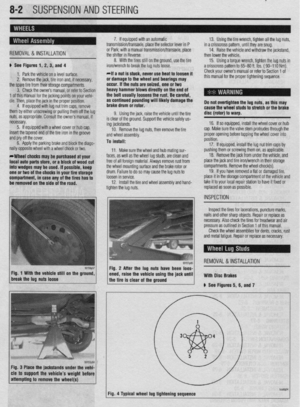 297
297 298
298 299
299 300
300 301
301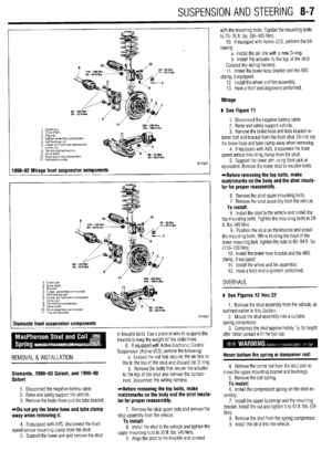 302
302 303
303 304
304 305
305 306
306 307
307 308
308 309
309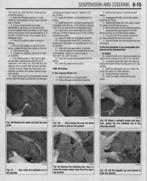 310
310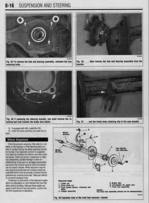 311
311 312
312 313
313 314
314 315
315 316
316 317
317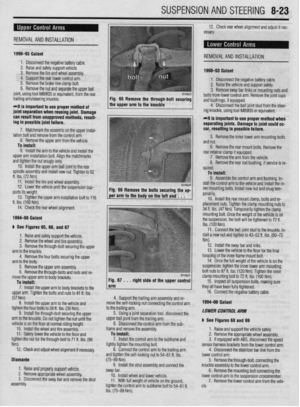 318
318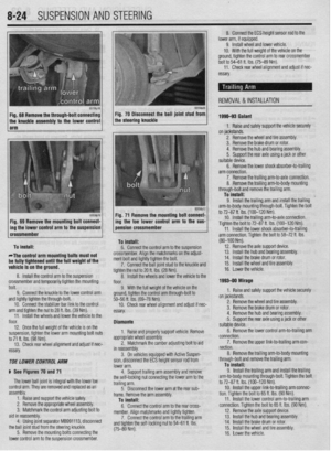 319
319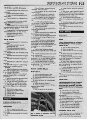 320
320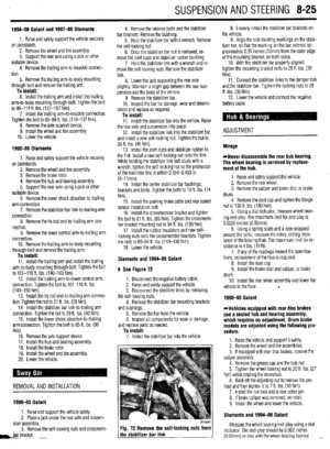 321
321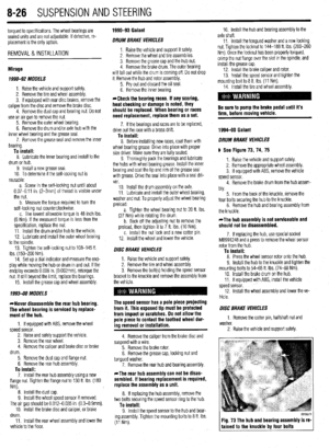 322
322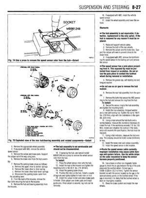 323
323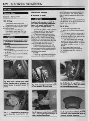 324
324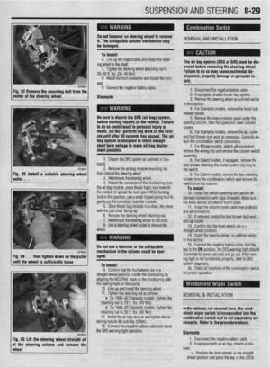 325
325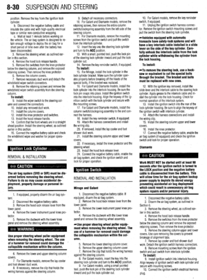 326
326 327
327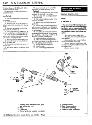 328
328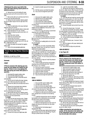 329
329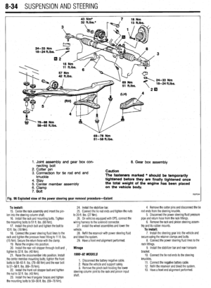 330
330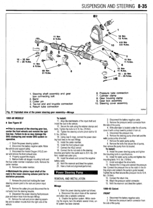 331
331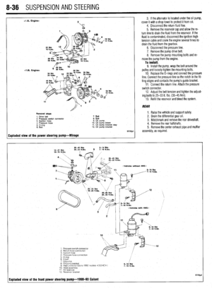 332
332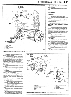 333
333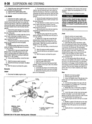 334
334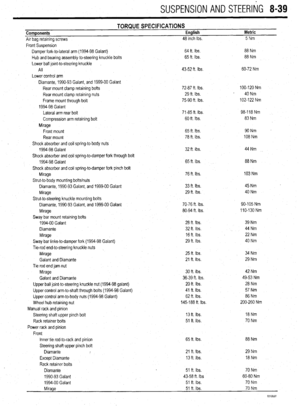 335
335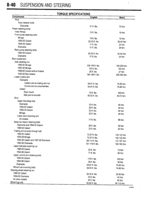 336
336 337
337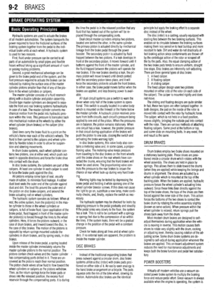 338
338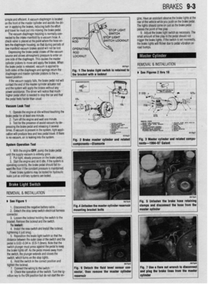 339
339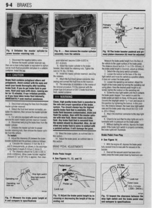 340
340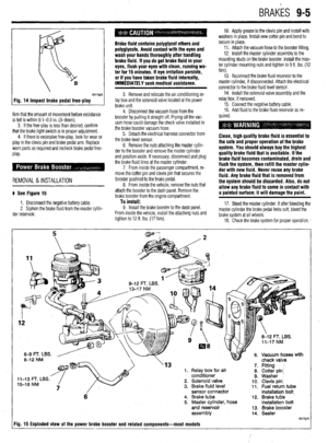 341
341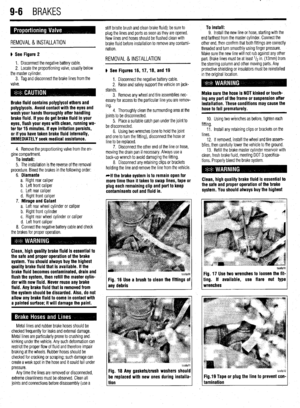 342
342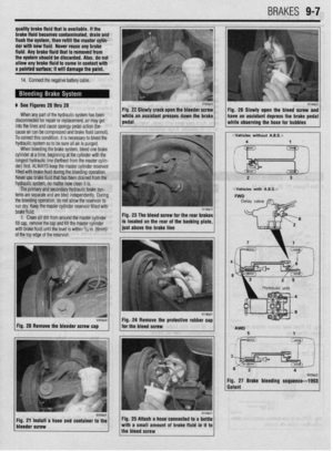 343
343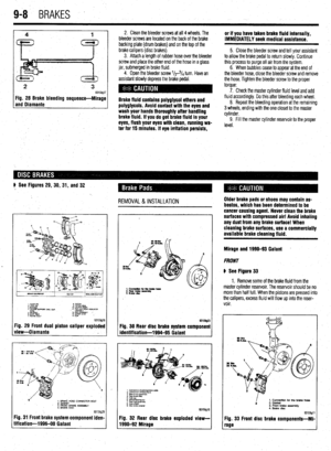 344
344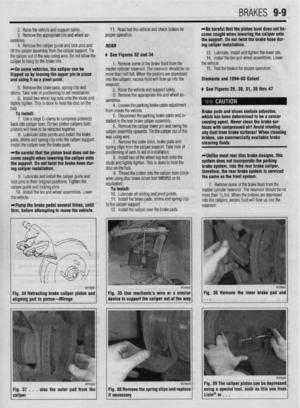 345
345 346
346 347
347 348
348 349
349 350
350 351
351 352
352 353
353 354
354 355
355 356
356 357
357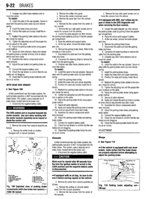 358
358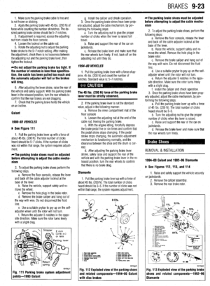 359
359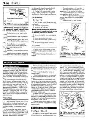 360
360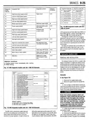 361
361 362
362 363
363 364
364 365
365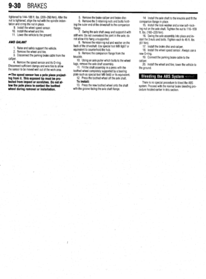 366
366 367
367 368
368 369
369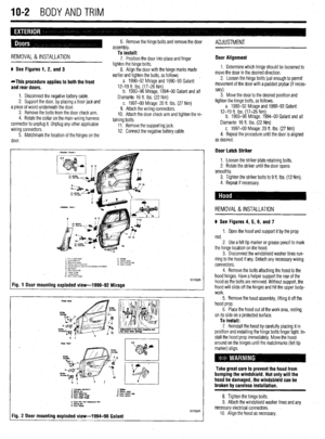 370
370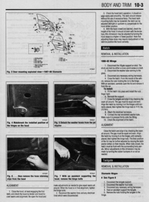 371
371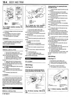 372
372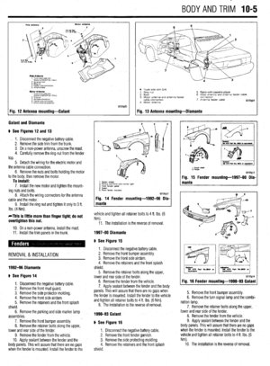 373
373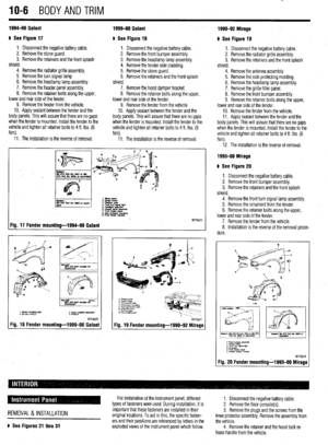 374
374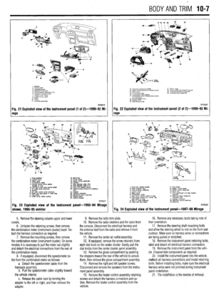 375
375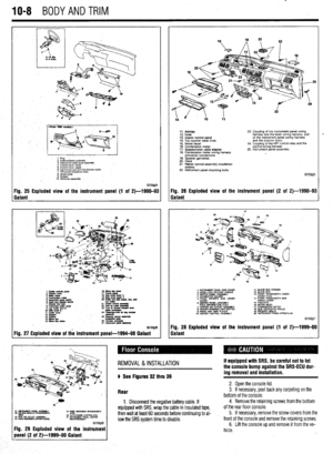 376
376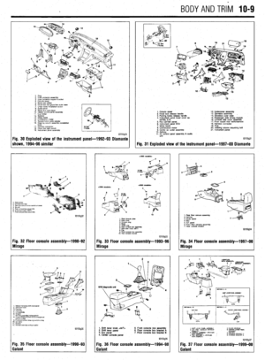 377
377 378
378 379
379 380
380 381
381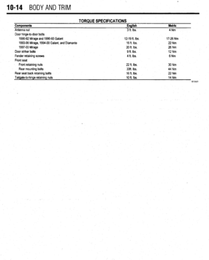 382
382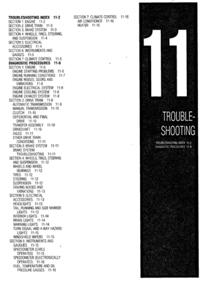 383
383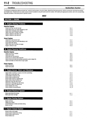 384
384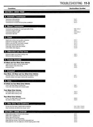 385
385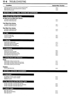 386
386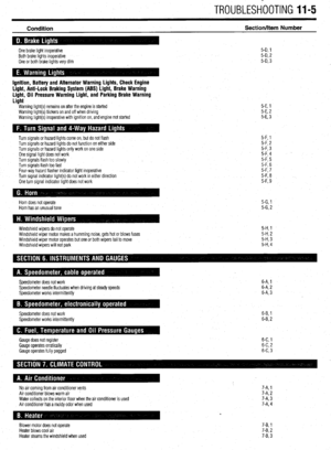 387
387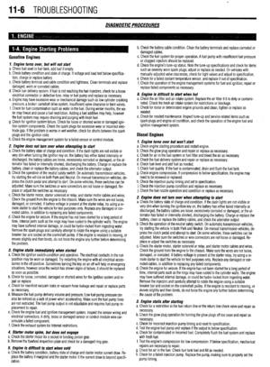 388
388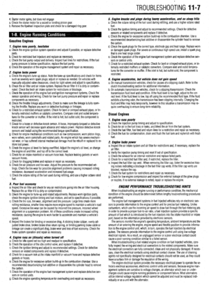 389
389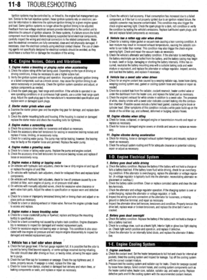 390
390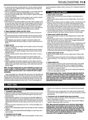 391
391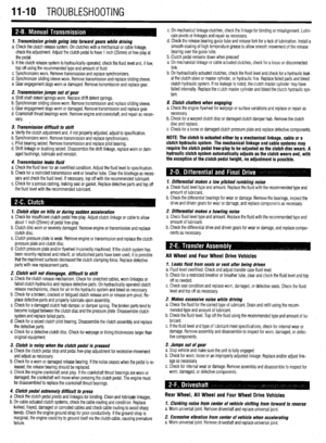 392
392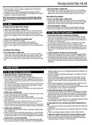 393
393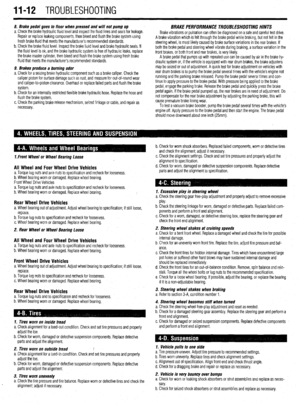 394
394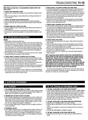 395
395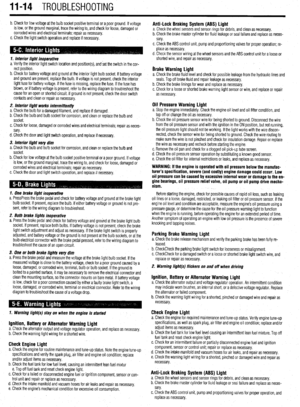 396
396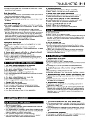 397
397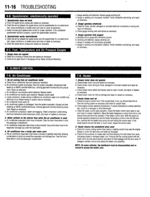 398
398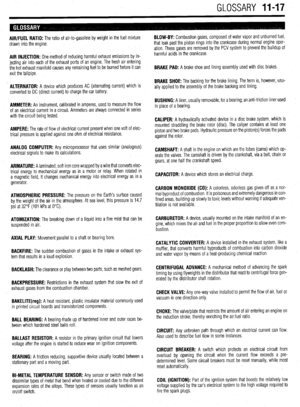 399
399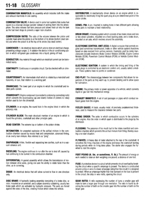 400
400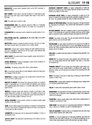 401
401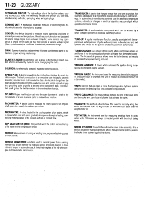 402
402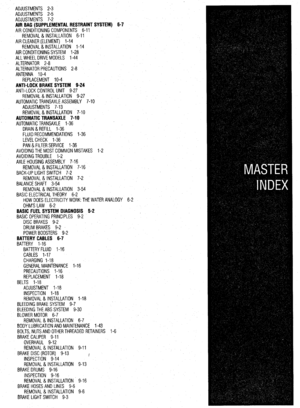 403
403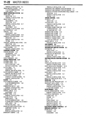 404
404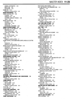 405
405 406
406 407
407