1900 MITSUBISHI DIAMANTE instrument cluster
[x] Cancel search: instrument clusterPage 204 of 408
UNDERSTANDING AND
TROUBLESHOOTING
ELECTRICAL SYSTEMS 6-2
BASIC ELECTRICALTHEORY 6-2
HOW DOES ELECTRICITY WORK:
THEWATERANALOGY 6-2
OHM'S LAW 6-2
ELECTRICALCOMPONENTS 6-2
POWERSOURCE 6-2
GROUND 6-3
PROTECTIVE DEVICES 6-3
SWITCHES&RELAYS 6-3
LOAD 6-3
WIRING & HARNESSES 6-3
CONNECTORS 6-4
TEST EQUIPMENT 6-4
JUMPER WIRES 6-4
TEST LIGHTS 6-4
MULTIMETERS 6-5
TROUBLESHOOTING ELECTRICAL
SYSTEMS 6-5
TESTING 6-5
OPEN CIRCUITS 6-5
SHORT CIRCUITS 6-6
VOLTAGE 6-6
VOLTAGE DROP 6-6
RESISTANCE 6-8
WIRE AND CONNECTORREPAIR 6-6
BATTERY CABLES 6-7
DISCONNECTING THE CABLES 6-7
AIR BAG (SUPPLEMENTAL
RESTRAINT SYSTEM) 6-7
GENERALINFORMATION 6-7
SERVICE PRECAUTIONS 6-7
DISARMING 6-7
REARMING 6-7
HEATING AND AIR
CONDITIONING 6-7
BLOWER MOTOR 6-7
REMOVAL &INSTALLATION 6-7
HEATER CORE 6-9 INSTRUMENTS AND SWITCHES 6-17
INSTRUMENTCLUSTER 6-17
REMOVAL &INSTALLATION 6-17
GAUGES 6-18
REMOVAL&INSTALLATION 6-18
WINDSHIELD WIPER SWITCH 6-19
REMOVAL&INSTALLATION 6-19
REARWINDOWWIPERSWITCH 6-19
REMOVAL &INSTALLATION 6-19
DIMMER SWITCH 6-19
REMOVAL & INSTALLATION 6-19 .
HEADLIGHT SWITCH 6-19
REMOVAL & INSTALLATION 6-19
LIGHTING 6-19
HEADLIGHTS 6-19
REMOVAL &INSTALLATION 6-19
AIMINGTHEHEADLIGHTS 6-20
SIGNAL AND MARKER LIGHTS 6-21
REMOVAL &INSTALLATION 6-21
CIRCUIT PROTECTION 6-27
FUSES 6-27
REPLACEMENT 6-27
FUSIBLE LINKS 6-27
CIRCUIT BREAKERS 6-28
RESETTING AND/OR
REPLACEMENT 6-28
FLASHERS 6-28
REPLACEMENT 6-28
WIRING DIAGRAMS 6-31
REMOVAL & INSTALLATION 6-9
AIR CONDITIONING COMPONENTS 6-11
REMOVAL & INSTALLATION 6-11
CONTROLCABLES 6-12
ADJUSTMENT 6-12
CONTROL PANEL 6-12
REMOVAL & INSTALLATION 6-12
CRUISE CONTROL 6-13
ENTERTAINMENT SYSTEMS 6-14
RADIO RECEIVER/AMPLIFIER/TAPE
PLAYER/CD PLAYER 6-14
SPEAKERS 6-14
REMOVAL & INSTALLATION 6-14
WINDSHIELD WIPERS AND
WASHERS 6-15
WINDSHIELD WIPER BLADE AND
ARM 6-15
REMOVAL & INSTALLATION 6-15
WINDSHIELD WIPER MOTOR 6-16 _
REMOVAL &INSTALLATION 6-16
WINDSHIELD WASHER PUMP 6-17
REMOVAL &INSTALLATION 6-17
Page 212 of 408
CHASSIS ELECtRldAL 6-9
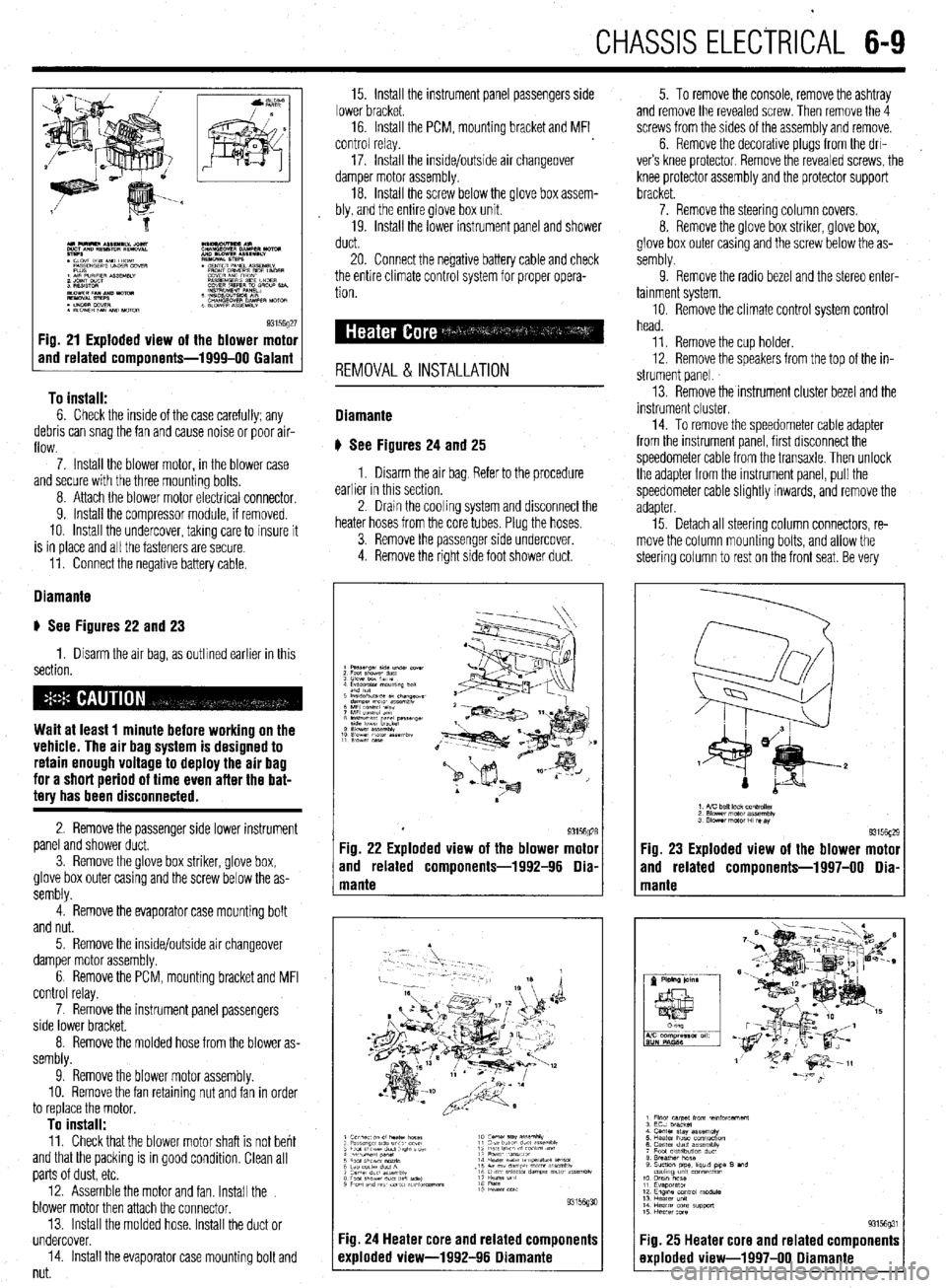
93156g27 Fig. 21 Exploded view of the blower motor
and related components-1999-00 Galant
To install:
6. Check the inside of the case carefully; any
debris can snag the fan and cause noise or poor air-
flow.
7. Install the blower motor, in the blower case
and secure with the three mounting bolts,
8. Attach the blower motor electrlcal connector,
9. Install the compressor module, if removed.
10. Install the undercover, takmg care to insure it
is in place and all the fasteners are secure.
11. Connect the negative battery cable.
Diamante
u See Figures 22 and 23
1. Disarm the air bag, as outlined earlier in this
section.
Wait at least 1 minute before working on the
vehicle. The air bag system is designed to
retain enough voltage to deploy the air bag
for a short period of time even after the bat-
tery has been disconnected.
2. Remove the passenger side lower instrument
panel and shower duct,
3. Remove the glove box striker, glove box,
glove box outer casing and the screw below the as-
sembly.
4. Remove the evaporator case mounting bolt
and nut.
5. Remove the inside/outside air changeover
damper motor assembly.
6 Remove the PCM, mounting bracket and MFI
control relay.
7. Remove the instrument panel passengers
side lower bracket.
8. Remove the molded hose from the blower as-
sembly.
9. Remove the blower motor assembly.
10. Remove the fan retaining nut and fan in order
to replace the motor,
To install: 11. Check that the blower motor shaft is not bent
and that the packing is in good condition, Clean all
parts of dust, etc.
12. Assemble the motor and fan. Install the
blower motor then attach the connector.
13. Install the molded hose. Install the duct or
undercover.
14. Install the evaporator case mounting bolt and
nut. 15. Install the instrument panel passengers side
lower bracket.
16. Install the PCM, mounting bracket and MFI
control relay.
17. Install the inside/outside air changeover
damper motor assembly.
18. Install the screw below the glove box assem-
bly, and the entire glove box unit.
19. Install the lower instrument panel and shower
duct.
20. Connect the negative battery cable and check
the entire climate control system for proper opera-
tion.
REMOVAL & INSTALLATION
Diamante
u See Figures 24
and 25
1. Disarm the air bag Refer to the procedure
earlier in this section.
2. Dram the cooling system and disconnect the
heater hoses from the core tubes. Plug the hoses.
3. Remove the passenger side undercover.
4. Remove the right side foot shower duct. 5. To remove the console, remove the ashtray
and remove the revealed screw. Then remove the 4
screws from the sides of the assembly and remove.
6. Remove the decorative plugs from the drl-
ver’s knee protector. Remove the revealed screws, the
knee protector assembly and the protector support
bracket.
7. Remove the steering column covers.
8. Remove the glove box striker, glove box,
glove box outer casing and the screw below the as-
sembly.
9. Remove the radio bezel and the stereo enter-
tainment system.
10. Remove the climate control system control
head.
11. Remove the cup holder.
12. Remove the speakers from the top of the in-
strument panel.
13. Remove the instrument cluster bezel and the
instrument cluster.
14. To remove the speedometer cable adapter
from the instrument panel, first disconnect the
speedometer cable from the transaxle. Then unlock
the adapter from the instrument panel, pull the
speedometer cable slightly inwards, and remove the
adapter
15. Detach all steering column connectors, re-
move the column mounting bolts, and allow the
steering column to rest on the front seat. Be very
Fig. 23 Exploded view of the blower motor
and related components-1997-00 Dia-
Fig. 25 Heater core and related components
exploded view-1997-00 Diamante
Page 213 of 408
640 CHASSIS ELECTRICAL
careful not to allow anything to come in contact with
the air bag unit.
16. Remove the glove box lamp assembly.
17. Remove the remaining instrument panel
mounting screws and remove the instrument panel
from the vehicle.
18. Remove the left side foot shower ductwork,
lap cooler duct and center duct.
19. Remove the front and center reinforcements
and center stay assembly.
20. Remove the air distribution duct assembly.
21. Detach all connectors from heater-box-
mounted items.
22. Remove the heater box mounting screws and
nut, then remove the unit from the vehicle.
23. Disassemble on a workbench. Remove the
heater core from the heater case.
To install:
24. Thoroughly clean and dry the inside of the
case and install the heater core and all related parts.
25. Install the heater unit to the vehicle and install
the mounting screws and nut. Be sure the evaporator
case and heater case are fitted together properly. At-
tach all connectors to heater-box-mounted items.
26. Install the air distribution duct assembly. In-
stall the front and center reinforcements and center
stay assembly.
27. Install the center duct, lap cooler duct and left
side foot shower duct.
28. Install the instrument panel and mounting
screws.
29. Install the glove box lamp assembly.
30. Secure the steering column and attach all
steering column connectors.
31. Install the speedometer cable adapter to the
instrument panel.
32. Install the instrument cluster and the instru-
ment cluster bezel.
33. Install the speakers to the top of the instru-
ment panel.
34. Install the cup holder.
35. Install the climate control system control
head.
36. Install the stereo entertainment system and
bezel.
37. Install the screw below the glove box assem-
bly, and the entire glove box unit.
38. Install the steering column covers.
39. Install the knee protector support bracket, the
protector and the decorative plugs.
40. Install the console and the ashtray. 41. Install the right side foot shower duct.
42. Install the passenger side undercover.
43. Connect the heater hoses to the core tubes.
44. Fill the cooling system.
45. Connect the negative battery cable and check
the entire climate control system for proper operation
and leaks.
Galant
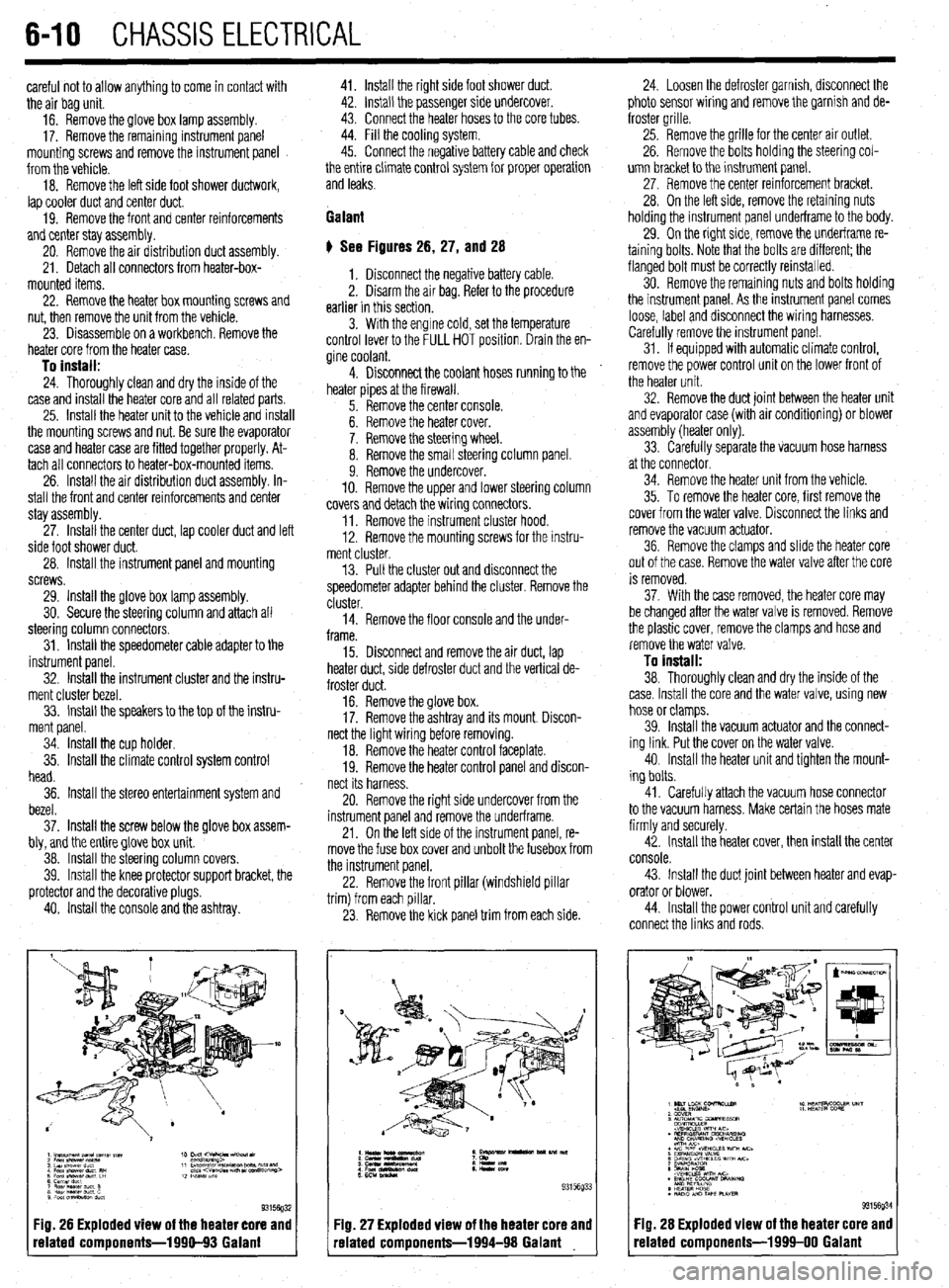
# See Figures 26, 27, and 28
1. Disconnect the negative battery cable.
2. Disarm the air bag. Refer to the procedure
earlier in this section.
3. With the engine cold, set the temperature
control lever to the FULL HOT position. Drain the en-
gine coolant.
4. Disconnect the coolant hoses running to the
heater pipes at the firewall.
5. Remove the center console.
6. Remove the heater cover.
7. Remove the steering wheel.
8. Remove the small steering column panel.
9. Remove the undercover.
10. Remove the upper and lower steering column
covers and detach the wiring connectors.
11. Remove the instrument cluster hood.
12. Remove the mounting screws for the instru-
ment cluster.
13. Pull the cluster out and disconnect the
speedometer adapter behind the cluster. Remove the
cluster.
14. Remove the floor console and the under-
frame.
15. Disconnect and remove the air duct, lap
heater duct, side defroster duct and the vertical de-
froster duct.
16. Remove the glove box.
17. Remove the ashtray and its mount. Discon-
nect the light wiring before removing.
18. Remove the heater control faceplate.
19. Remove the heater control panel and discon-
nect its harness.
20. Remove the right side undercover from the
instrument panel and remove the underframe.
21. On the left side of the instrument panel, re-
move the fuse box cover and unbolt the fusebox from
the instrument panel.
22. Remove the front pillar (windshield pillar
trim) from each pillar.
23. Remove the kick panel trim from each side.
Fig. 26 Exploded view of the heater core and
related components-1990-93 Galant
:IQ. 27 Exploded view of the heater core and
-elated components-1994-98 Galant 24. Loosen the defroster garnish, disconnect the
photo sensor wiring and remove the garnish and de-
froster grille.
25. Remove the grille for the center air outlet.
26. Remove the bolts holding the steering col-
umn bracket to the instrument panel.
27, Remove the center reinforcement bracket.
28. On the left side, remove the retaining nuts
holding the instrument panel underframe to the body.
29. On the right side, remove the underframe re-
taining bolts. Note that the bolts are different; the
flanged bolt must be correctly reinstalled.
30. Remove the remaining nuts and bolts holding
the instrument panel. As the instrument panel comes
loose, label and disconnect the wiring harnesses.
Carefully remove the instrument panel.
31. If equipped with automatic climate control,
remove the power control unit on the lower front of
the heater unit.
32. Remove the duct joint between the heater unit
and evaporator case (with air conditioning) or blower
assembly (heater only).
33. Carefully separate the vacuum hose harness
at the connector.
34. Remove the heater unit from the vehicle.
35. To remove the heater core, first remove the
cover from the water valve. Disconnect the links and
remove the vacuum actuator.
36. Remove the clamps and slide the heater core
out of the case. Remove the water valve after the core
is removed.
37. With the case removed, the heater core may
be changed after the water valve is removed. Remove
the plastic cover, remove the clamps and hose and
remove the water valve.
To install:
38. Thoroughly clean and dry the inside of the
case. Install the core and the water valve, using new
hose or clamps.
39. Install the vacuum actuator and the connect-
ing link. Put the cover on the water valve.
40. Install the heater unit and tighten the mount-
ing bolts.
41. Carefully attach the vacuum hose connector
to the vacuum harness. Make certain the hoses mate
firmly and securely.
42. Install the heater cover, then install the center
console.
43. Install the duct joint between heater and evap-
orator or blower.
44. Install the power control unit and carefully
connect the links and rods.
Fig. 28 Exploded view of the heater core and
related components-1999-00 Galant
Page 214 of 408
CHASSIS ELECTRICAL 6-11
45. Install the heater hoses under the hood.
46. Install the mstrument panel by reversing its
removal procedure.
47. Install the center console.
48. install the upper and lower steering column
covers.
49. Install the center panel undercover.
50. Install the small column panel.
51. Install the steering wheel.
52. Fill the cooling system.
53. Connect the negative battery cable and check
the entire climate control system for proper operation
and leaks.
Mirage
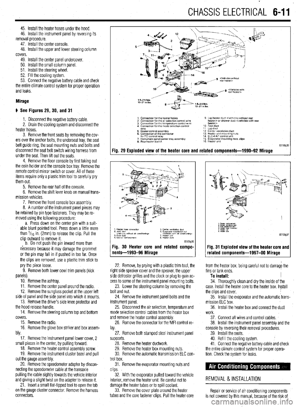
# See Figures 29, 30, and 31
1. Disconnect the negative battery cable.
2. Drain the cooling system and disconnect the
heater hoses.
3. Remove the front seats by removing the cov-
ers over the anchor bolts, the underseat tray, the seat
belt guide ring, the seat mounting nuts and bolts and
disconnect the seat belt switch wiring harness from
under the seat. Then lift out the seats
4. Remove the floor console by first taking out
the coin holder and the console box tray. Remove the
remote control mirror switch or cover. All of these
items require only a plastic trim tool to carefully pry
them out.
5. Remove the rear half of the console.
6. Remove the shift lever knob on manual trans-
mission vehicles.
7. Remove the front console box assembly.
8. A number of the instrument panel pieces may
be retamed by pin type fasteners. They may be re-
moved using the following procedure:
a. Press down on the center pin with a suit-
able blunt pointed tool. Press down a little more
than l/re in. (2mm) to release the clip. Pull the
clip outward to remove it.
b. Do not oush the oin inward more than
necessary because it may damage the grommet
or the pin may fall in if pushed in too far. Once
the clips are removed, use a plastic trim stick to
pry the piece loose.
9. Remove both lower cowl trim panels (kick
panels).
10. Remove the ashtray.
11. Remove the center panel around the radio.
12. Remove the sunglass pocket at the upper left
side of panel and the side panel into which it mounts,
13. Remove the drivers side knee protector and
the hood release handle.
14. Remove the steering column top and bottom
covers.
15. Remove the radio.
16. Remove the glove box striker and box assem-
bly.
17. Remove the instrument panel lower cover, 2
small pieces in the center, by pulling forward.
18. Remove the heater control assembly screw.
19. Remove the instrument cluster bezel and pull
out the Qauge assembly.
20. Remove the speedometer adapter by discon-
necting the speedometer cable at the transaxle
pulling the cable Sightly towards the vehicle interior
and giving a Slight twist on the adapter to release it.
21. Insert a small flat-tipped tool to open the tab
on the QauQe cluster connector. Remove the harness
connectors.
Fig. 29 Exploded view of the heater core and related components-1990-92 Mirage
93l%Q% Fig. 30 Heater core and related compo-
nents-1993-96 Mirage
22. Remove, by prying with a plastic trim tool, the
right side speaker cover and the speaker, the upper
side defroster grilles and the clock or plug to gain ac-
cess to some of the instrument panel mounting bolts.
23. Lower the steering column by removing the
bolt and nut.
24. Remove the instrument panel bolts and the
instrument panel.
25 Drsconnect the air selection, temperature and
mode selection control cables from the heater box
and remove the heater control assembly.
26. Remove the connector for the MFI control re-
lay.
27. Remove both stamped steel instrument panel
supports.
28. Remove the heater ductwork.
29. Remove the heater box mounting nuts.
30 Remove the automatic transmission ELC con-
trol box.
31. Remove the evaporator mounting nuts and
clips.
32. With the evaporator pulled toward the vehicle
interior, remove the heater unit. Be careful not to
damage the heater tubes or to spill coolant.
33. Remove the cover plate around the heater
tubes and the core fastener clips. Pull the heater core 34. Thoroughly clean and dry the inside of the
case. Install the heater core to the heater box. Install
the clips and cover,
35. Install the evaporator and the automatic trans-
mission ELC box.
36. Install the heater box and connect the duct
Fig. 31 Exploded view of the heater core and
related components-1997-00 Mirage
from the heater box, being careful not to damage the
fins or tank ends.
To install: I
work.
37. Connect all wires and control cables,
38. Install the instrument panel assembly and the
console by reversmg their removal procedures.
39 Install the seats.
40. Refill the cooling system.
41. Connect the negative battery cable and check
the entire climate control system for proper opera-
tion Check the system for leaks.
REMOVAL &INSTALLATION
Repair or service of air Conditioning components
is not covered by this manual, because of the risk of
Page 220 of 408
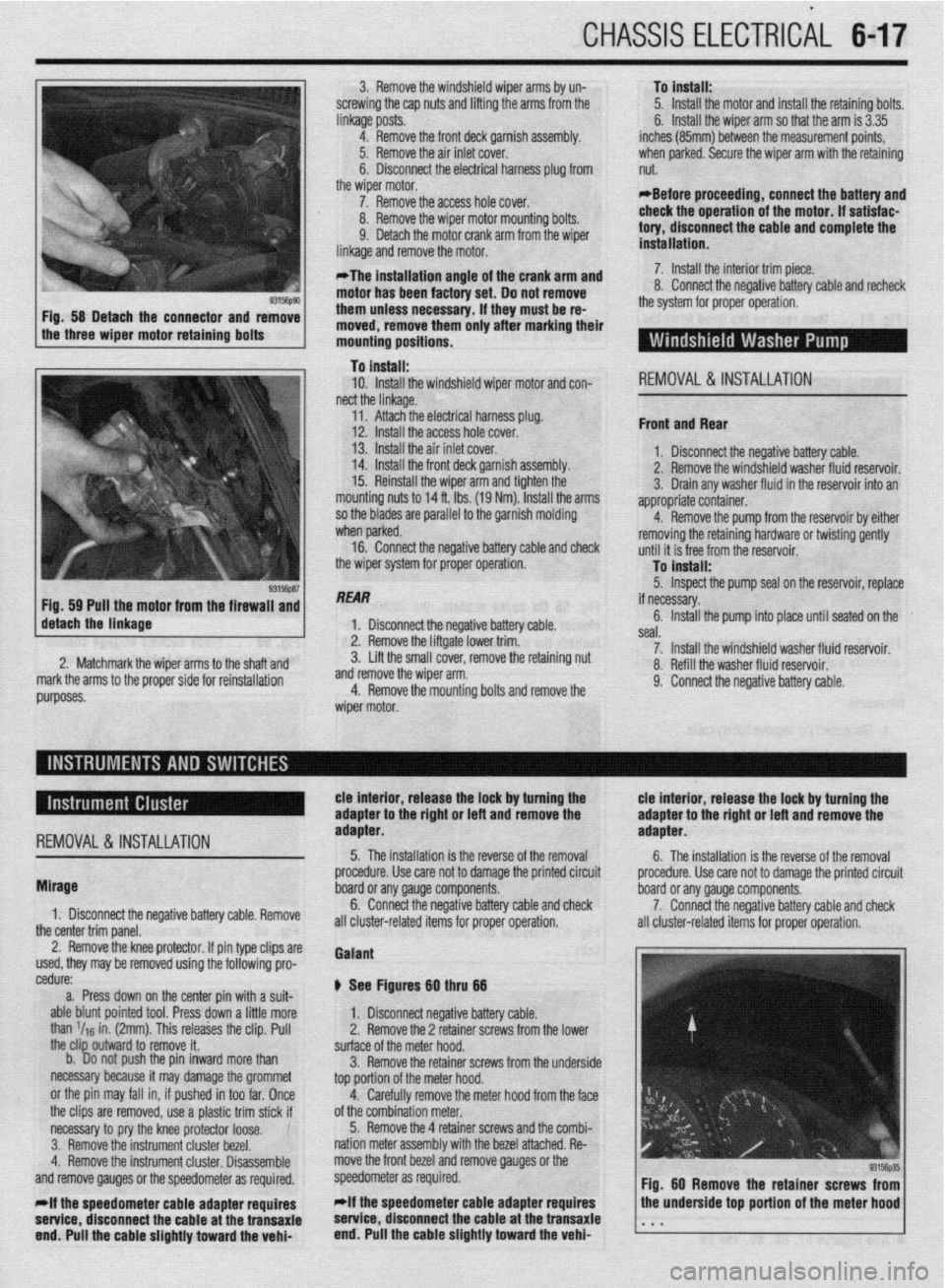
CHASSIS ELECTRICAL 647
3. Remove the windshield wiper arms by un-
screwing the cap nuts and lifting the arms from the
linkage posts.
4. Remove the front deck garnish assembly.
Iver.
xl harness plug from
,I6 #-n\,LIr 5. Remove the air inlet c(
6. Disconnect the electric
the wiper motor.
7. Remove the access ho,, LIVIGil. To install:
5. Install the motor and install the retaining bolts.
6. Install the wiper arm so that the arm is 3.35
inches (85mm) between the measurement points,
when parked. Secure the wiper arm with the retaining
nut.
*Before proceeding, connect the battery and
8. Remove the wiper motor mounting bolts.
9. Detach the motor crank arm from the wiper
linkane and remnve the mntnr
motor has been factory set. Do not remove
them unless necessary. if they must be re-
moved, remove them only after marking their
mounting positions. check the operation of the motor. if satisfae-
tory, disconnect the cable and complete the
installation.
o. WIIIIW LIE Il~&WVt: vatreryoable and recheck
the system for proper operation.
..-
a- - ‘- _ _ _ . _ _ _
*The installation angle of the crank arm and 7. Install the interior trim piece
n II ^_^^^ IAL- -^I-I:..- L-AL--
To install:
10. Install the windshield wiper motor and con-
REMOVAL&INSTALLATION nect the linkage.
I 14. Install the front deck garnish assembly. I. YIV”“I1IIYVL VI” “UyuL’.” “UL’“‘, UUUIU. 2. Remove the windshield washer fluid resarvnir
’ 11. Attach the electrical harness plug.
12. Install the access hole cover.
13. Install the air inlet cover.
15. Reinstall the wiper arm and tighten the
mounting nuts to 14 ft. Ibs. (19 Nm). Install the arms
so the blades are parallel to the garnish molding -
Front and Rear
1 nivnnnprt the nonatiua haltorv rahlo
3. Drain any washer fluid in the reservoir into an
appropriate container.
4.
I when parked. Remove the pump from the reservoir by either
16. Connect the neaative batterv cable and check removing the retaining hardware or twisting gently
tlntil it is frpp frnm thP rosorvnir the wiper system for proper operation.
lo Install:
5. Inspect the pump seal on the reservoir, replace
/ de&h the linkage Fig 59 Pull the motor from the firewaii and
“‘%‘y 1 ““I”“,,,,,, the if necessary.
1 1 Disconn& thP rwnativo hatton/ rahlm 6. Install the pump into place until seated on the .I,” ~‘“p.L’,” YULL”‘, -YI”. liftgate lower trim. seal.
3: Lift the smatr CUVBI, I~IIIUV~ tilt: lfAdllllll~ IIUL II --. .-- -^- ^..^ .L^ -_,_:..:-- -.A 7. Install the windshield washer fluid reservoir. 2. Matchmark the wirier arms tn the shaft and A Refill thp wxhpr fllk-l rpqprvnir markthe arms to the proper side for reinstallation and remove the wiper arm.
4. Remove the mountina bolts and remove the “. .,“...S .V.” ....“III. ,*..*” IYUY..“m,.
9. Connect the negative battery cable.
REMOVAL&INSTALLATION
tie interior, release the lock by turning the tie interior, release the lock by turning the
adapter to the right or left and remove the adapter to the rigM or left and remove the
adapter. adapter.
5. The installation is the reverse of the removal
6. The installation is the reverse of the removal
Mirage
1. Disconnect the negative battery cable. Remove
the center trim panel. procedure. Use care not to damage the printed circuit procedure. Use care not to damage the printed circuit
board or any gauge components.
board or any gauge components.
6. Connect the negative battery cable and check
7. Connect the negative battery cable and check
all cluster-related items for proper operation. i III cluster-related items for proper operation.
2. Remove the knee protector. If pin type clips are
used, they may be removed using the following pro-
cedure:
a. Press down on the center pin with a suit-
able blunt pointed tool. Press down a little more
than ‘IIS in. (2mm). This releases the clip. Pull
the clip outward to remove it.
b. Do not push the pin inward more than
necessary because it may damage the grommet
or the pin may fall in, if pushed in too far. Once
the clips are removed, use a plastic trim stick if
necessary to pry the knee protector loose.
3. Remove the instrument cluster bezel.
4. Remove the instrument cluster. Disassemble
and remove gauges or the speedometer as required.
*if the speedometer cable adapter requires
setvice, disconnect the cable at the transaxie
end. Pull the cable slightly toward the vehi- Gaiant
@ See Figures Bg thru 66
1. Disconnect negative battery cable.
2. Remove the 2 retainer screws from the lower
surface of the meter hood.
3. Remove the retainer screws from the underside
top portion of the meter hood.
4. Carefully remove the meter hood from the face
of the combination meter.
5. Remove the 4 retainer screws and the combi-
nation meter assembly with the bezel attached. Re-
move the front bezel and remove gauges or the
speedometer as required.
*if the speedometer cable adapter requires
service, disconnect the cable at the transaxie
end. Pull the cable slightly toward the vehi-
Page 221 of 408
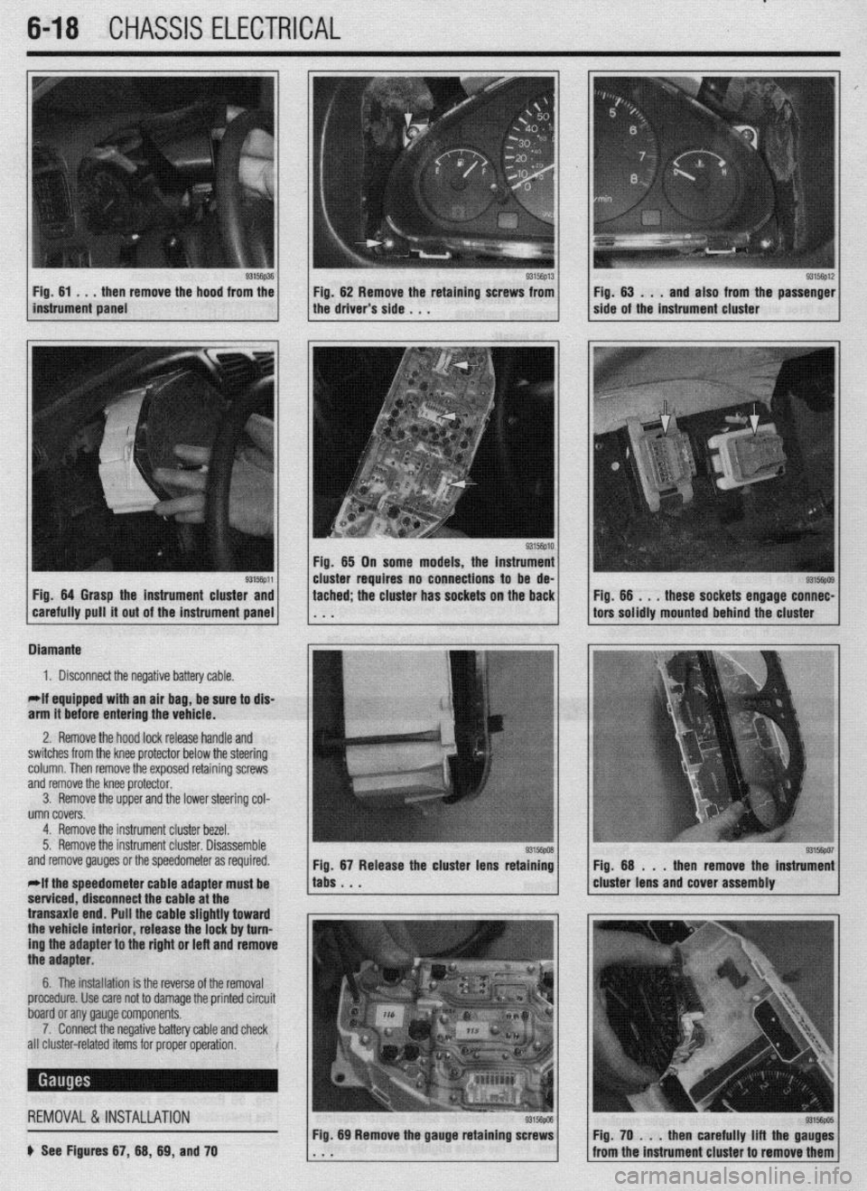
.
6-18 CHASSIS ELECTRICAL
Fig. 64 Grasp the instrument cluster and
carefully pull it out of the instrument panel tached; the cluster has sockets on the back Fig. 66 . , .
these sockets engage connec-
tors solidly mounted behind the cluster
Diamante
1. Disconnect the negative battery cable.
*If equipped with an air bag, be sure to dis-
arm it before entering the vehicle.
2. Remove the hood lock release handle and
switches from the knee protector below the steering
column. Then remove the exposed retaining screws
and remove the knee protector.
3. Remove the upper and the lower steering col-
umn covers.
4. Remove the instrument cluster bezel.
5. Remove the instrument cluster. Disassemble
and remove gauges or the speedometer as required.
*If the speedometer cable adapter must be
serviced. disconnect the cable at the
transaxle end. Pull the cable slightly toward
the vehicle interior, release the lock by turn-
ing the adapter to the right or left and remove
the adapter.
6. The installation is the reverse of the removal
procedure. Use care not to damage the printed circuit
board or any gauge components,
7. Connect the negative battery cable and check
all cluster-related items for proper operation.
REMOVAL &INSTALLATION
I
b See Figures 67, 66, 69, and 70
83156pD6 Fig. 69 Remove the gauge retaining screws Fig. 70 . . . then carefully lift the gauges
from the instrument cluster to remove them
Page 222 of 408
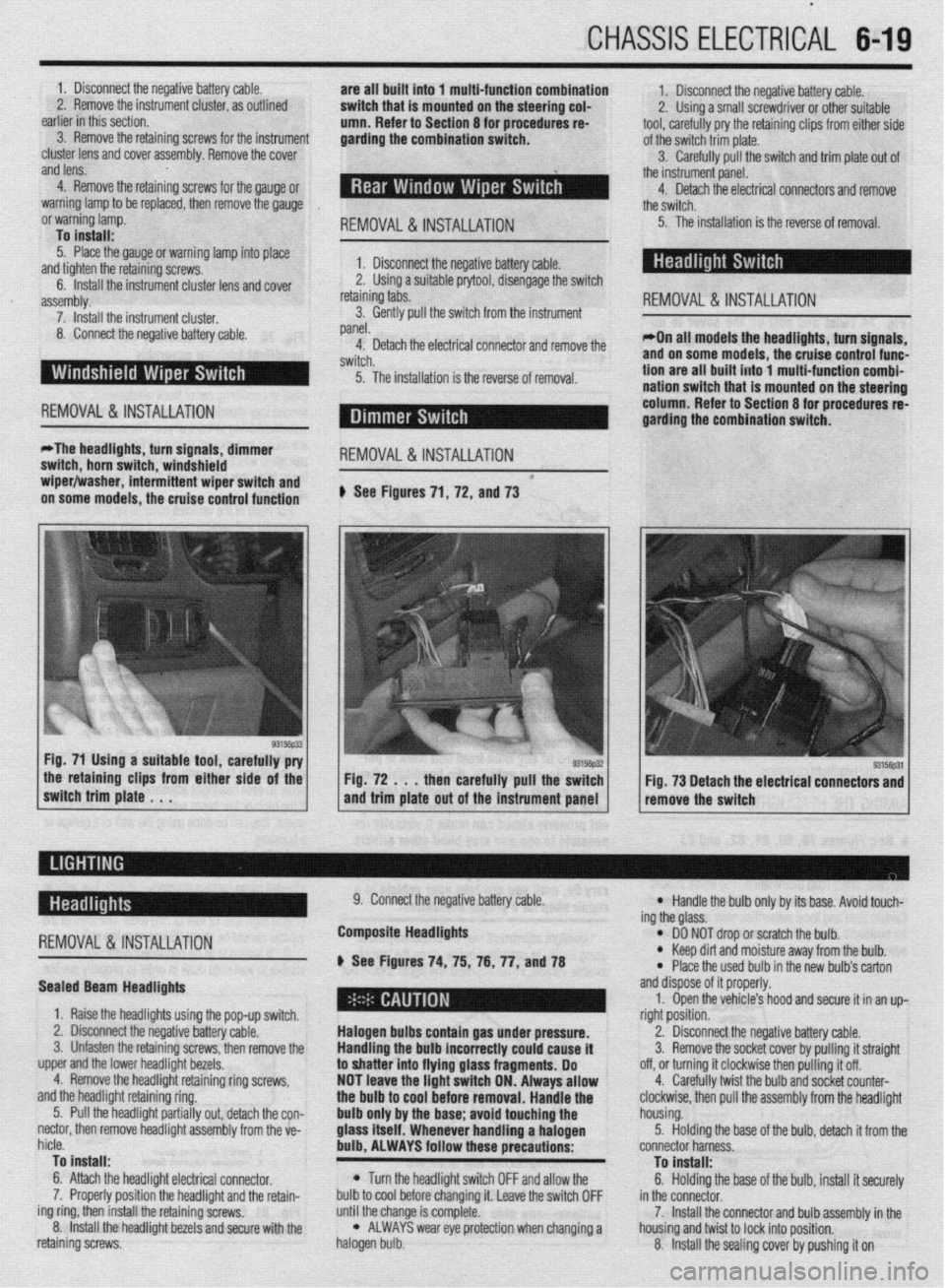
CHASSIS ELECTRICAL 6-19
1. Disconnect the negative battery cable.
are all built into 1 multi-function combination
2. Remove the instrument cluster, as outlined 1. Disconnect the negative battery cable.
earlier in this section. switch that is mounted on the steering col-
2. Using a small screwdriver or other suitable
umn. Refer to Section 8 for procedures re-
3. Remove the retaining screws for the instrument tool, carefully pry the retaining clips from either side
garding the combination switch.
cluster lens and cover assembly. Remove the cover of the switch trim plate.
3.
and lens. Carefully pull the switch and trim plate out of
,
4. Remove the retaining screws for the gauge or the instrument panel.
4. Detach the electrical connectors and remove
warning lamp to be replaced, then remove the gauge
the switch.
or warning lamp.
REMOVAL&INSTALLATION : 5. The installation is the reverse of removal.
To install:
5. Place the gauge or warning lamp into place
and tighten the retaining screws. 1. Disconnect the negative battery cable.
6. Install the instrument cluster lens and cover 2. Using a suitable prytool, disengage the switch
assembly. retaining tabs.
REMOVAL &INSTALLATION 7. Install the instrument cluster. 3. Gently pull the switch from the instrument
8. Connect the negative battery cable. panel.
4. Detach the electrical connector and remove the *On all models the headlights, turn signals,
switch. and on some models, the cruise control func-
5. The installation is the reverse of removal. tion are all built into 1 multi-function combi-
nation switch that is mounted on the steerinq
REMOVAL &INSTALLATION column. Refer to Section 8 for procedures 6
garding the combination switch.
*The headlights, turn signals, dimmer
switch, horn switch, windshield
REMOVAL &INSTALLATION
wiper/washer, intermittent wiper switch and *
on some models, the cruise control function # See Figures 71, 72, and 73
the retaining clips from either side of the
switch trim plate . . . Fig. 72 . . . then carefully pull the switch
and trim plate out of the instrument panel Fig. 73 Detach the electrical connectors and
remove the switch
-
REMOVAL &INSTALLATION
Sealed Beam Headlights
1. Raise the headlights using the pop-up switch.
2. Disconnect the negative battery cable.
3. Unfasten the retaining screws, then remove the
upper and the lower headlight bezels.
4. Remove the headlight retaining ring screws,
and the headlight retaining ring.
5. Pull the headlight partially out, detach the con-
nectar, then remove headlight assembly from the ve-
hicle.
To install:
6. Attach the headlight electrical connector.
7. Properly position the headlight and the retain-
ing ring, then install the retaining screws.
8. Install the headlight bezels and secure with the
retaining screws. 9. Connect the negative battery cable.
Composite Headlights
6 See Figures 74, 75, 76, 77, anU78
Halogen bulbs contain gas under pressure.
Handling the
bulb incorrectly could cause it
to shatter into flying glass fragments. Do
NOT leave the light switch ON. Always allow
the bulb to cool before removal. Handle the
bulb only by the base; avoid touching the
glass itself. Whenever handling a halogen
bulb, ALWAYS follow these precautions:
l Turn the headlight switch OFF and allow the
bulb to cool before changing it. Leave the switch OFF
until the change is complete.
l ALWAYS wear eye protection when changing a
halogen bulb.
l Handle the bulb only by its base. Avoid touch-
ing the glass.
l DO NOT drop or scratch the bulb. l Keep dirt and moisture away from the bulb.
* Place the used bulb in the new bulb’s carton
and dispose of it properly.
1. Open the vehicle’s hood and secure it in an up-
right position.
2. Disconnect the negative battery cable.
3. Remove the socket cover by pulling it straight
off, or turning it clockwise then pulling it off.
4. Carefully twist the bulb and socket counter-
clockwise, then pull the assembly from the headlight
housing.
5. Holding the base of the bulb, detach it from the
connector harness.
To install:
6. Holding the base of the bulb, install it securely
in the connector.
7. Install the connector and bulb assembly in the
housing and twist to lock into position.
8. Install the sealing cover by pushing it on
Page 228 of 408
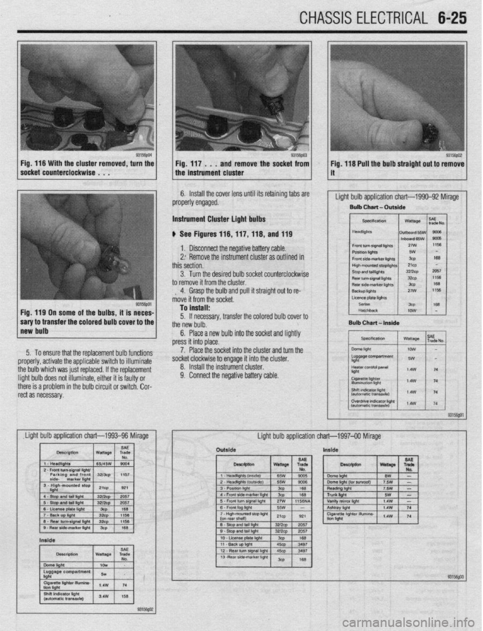
CHASSIS ELECTRICAL 6-25
ove the socket from ig. 118 Pull the bulb straight out to remove
6. Install the cover lens until its retaining tabs are
properly engaged. ’
Light bulb application chart-1990-92 Mirage
Bulb Chart - Outaide
Instrument Cluster light bulbs
b See Figures 116,llf,ll8, and 119
1. Disconnect the negative battery cable.
2: Remove the instrument cluster as outlined in
this section.
3. Turn the desired bulb socket counterclockwise
to remove it from the cluster.
, 4. Grasp the bulb and pull it straight out to re-
move it from the socket.
I 1 Lmelatel~hls
Fig. 119 On some of the bulbs, it is neces-
1 ;;tbqrlrnsferthe colore ’ ’ ” . .’ ’
1 EL&
!a OUID cover IO me
Bulb Chart-In
*__. . __.
, , JvR,,Is~,,o~
press i+ in+n n,app
II llll” ~“UVV.
To install:
5. If necessary, transfer the colored bulb cover to
the new bulb.
6. Place a new bulb into the socket and lightly
Place the socket into the cluster and turn the
,“. II pithpr it ic faldtv nr 9. Connect the negative battery cable.
I
Outside Inside