Page 231 of 408

.
6-28 CHASSIS ELECTRICAL
Do not just replace the fosible link to correct
a problem! RESETTlNGAND/OR REPLACEMENT REPLACEMENT
When replacing all fusible links, they are to be re-
placed with the same type of prefabricated link avail-
able from your vehicle manufacturer. Circuit breakers are located inside the fuse panel.
They are automatically reset when the problem cor-
rects itself, is repaired, or the circuit cools down to
allow operation again. The turn signal and hazard flasher unit is located
in the interior fuse panel located under the driver’s
left side knee protector. They are replaced by simply
pulling them straight out. Note that the prongs are
arranged in such a way that the flasher must be prop-
erly oriented before attempting to install it. Turn the
flasher until the orientation of the prongs is correct
and simply push it firmly in until the prongs are fully
engaged.
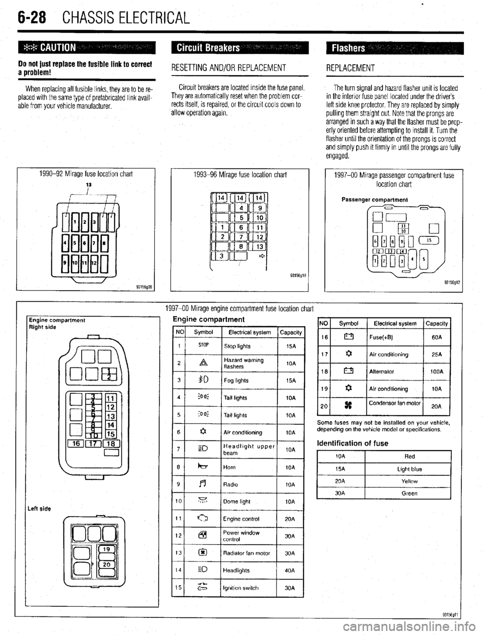
1990-92 Mirage fuse location chart
,-Lw 1993-96 Mirage fuse location chart
93156glO
1997-00 Mirage passenger compartment fuse
location chart
1997-00 Mirage engine compartment fuse location chart
Engine compartment
9ight side Engine compartment
I
I I 12 Power window
Control 30A
13
@I Radiator fan motor 30A
14 E-J
Headllghls 40A
15
;2” lgnttlon switch 30A NO Symbol Electrical system Capacrty
16 0 Fuse(+B) 60A
Some fuses may not be installed on your vehicle,
depending on the vehicle model or specihcations.
Identification of fuse
i0A Red
Page 232 of 408

CHASSIS ELECTRlCiL 6-29
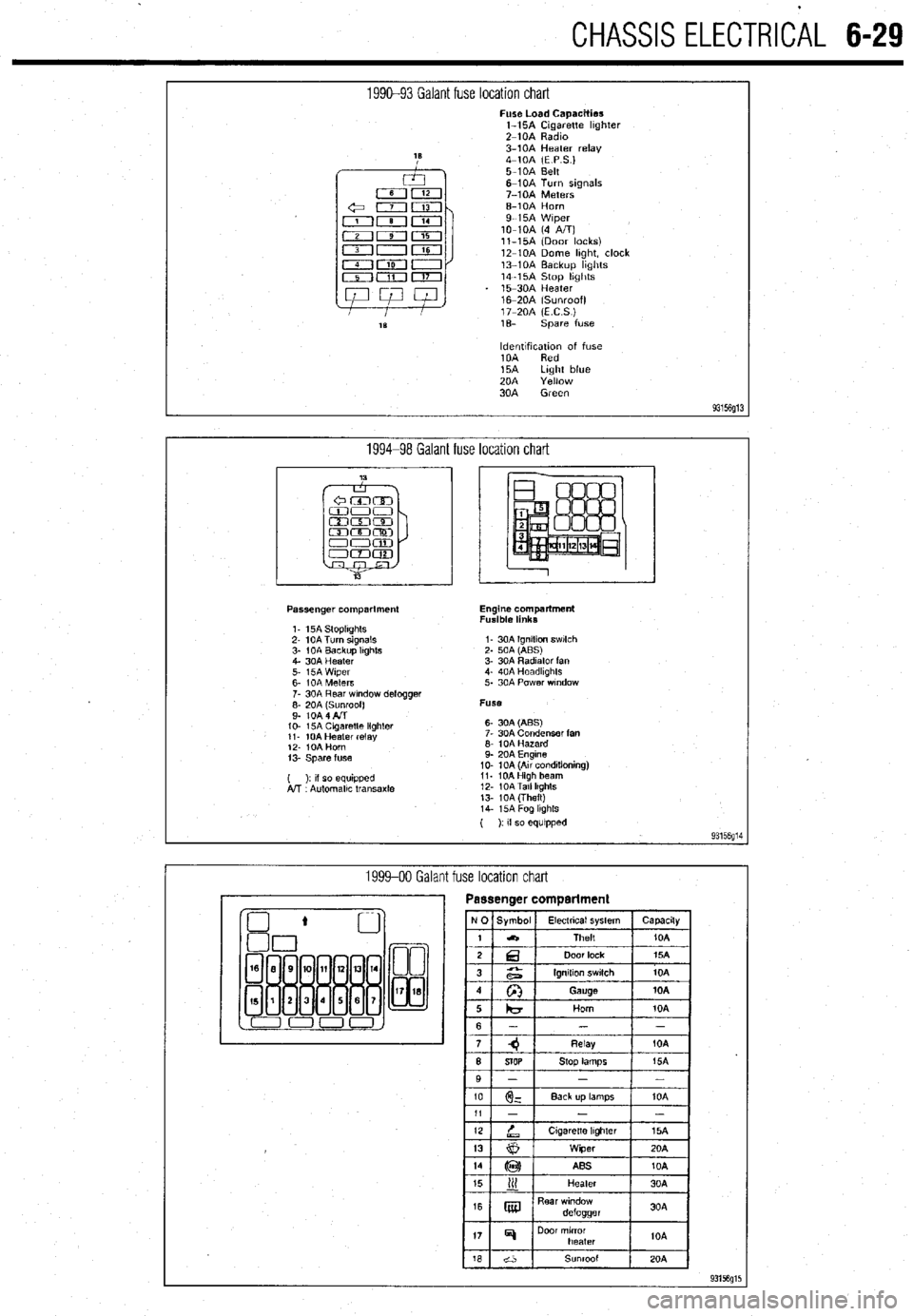
1990-93 Galant fuse location chart Fuse Load Capacities
l-15A Cigarette hghter
Z-10A Radm
3-10A Heater relay
4-10A (E P S.)
5-10A Belt
6-10A Turn signals
7-10A Meters
6-10A Horn
9-15A Wiper
lo-10A (4 A/T)
ll-15A (Door locks)
12-10A Dome hght, clock
13-10A Backup hghts
14-15A Stop hghts
15-30A Heater
16m20A (Sunroof)
17-20A (ECS)
1% spare fuse
ldentlfxation of fuse
10A Red
15A Light blue
20A Yellow
30A Green
93156g13
1994-98 Galant fuse location chart
Passenger compartment
1. 15A StoplIghts
2- 10A Turn signals
3- 1 OA Backup Itghts
4. 30A Heater
5. i5A Wiper
6- IOA Meters
7. 30A Rear wndow defogger
;: fo& fl$oof)
IO- 15A Cagaretle lighler
11. 10A Heater relay
12. IOA Horn
13. Spare fuse
( ): II so equipped
A!T Automallc transaxle Engine compartment
Fusible links
I- 30A Ignition swlch
2. 50A (ABS)
3. 30A Radiator fan
4. 40A Headkghts
5. 30A Power wndow
Fuse
6- 30A (ABS)
7. 30A Condenser fan
6. 10A Hazard
9. 20A Engine
10. 10A (Au conditioning)
11. 10AHigh beam
12. 10ATall lkghts
13. 10A (Theft)
14. i5A Fog lkghls
( ): If so equipped
93156g14
1999-00 Galant fuse location chart
Page 233 of 408
6-30 CHASSIS ELECTRICAL
1992-96 Diamante fuse location chart
I
Fuse load caaacities 15 -2OA Horn
16 - 20A (E.C.S.)
1 - 15A Cigarette lighter 17 - spare fuse
2 - 10A Radio
3 - 10A Heater relay, (Power window ( ) indicates optlonal equipment
relay) E P.S.: Electronic Control Power Steer-
4 - 10A (E.P.S) ing
5 - 10A Turn signals, SRS E.C.S.: Electronic Control Suspension
6 - 10A Meters, SRS SRS~ Supplement Restratnt System
7 - 15A Wiper A/T: Automatic Transaxle
8-10A (4AIT)
9- 15A Steering handle lock, (Door
locks)
lo- 10A Dome light, Clock
11 - 10A Backup lights
12 -2OA StoplIghts
13 -3OA Heater
14 - 20A (Sunroof)
93156fllE
1997-00 Diamante passenger compartment fuse location chart No Symbol Electrical System
I capactty
I
Spare fuses are contained in the fuse housing
use a fuse of the same capacity for replacement.
199740 Diamante encline
compartment fuse location chart