1900 MITSUBISHI DIAMANTE remote control
[x] Cancel search: remote controlPage 214 of 408

CHASSIS ELECTRICAL 6-11
45. Install the heater hoses under the hood.
46. Install the mstrument panel by reversing its
removal procedure.
47. Install the center console.
48. install the upper and lower steering column
covers.
49. Install the center panel undercover.
50. Install the small column panel.
51. Install the steering wheel.
52. Fill the cooling system.
53. Connect the negative battery cable and check
the entire climate control system for proper operation
and leaks.
Mirage
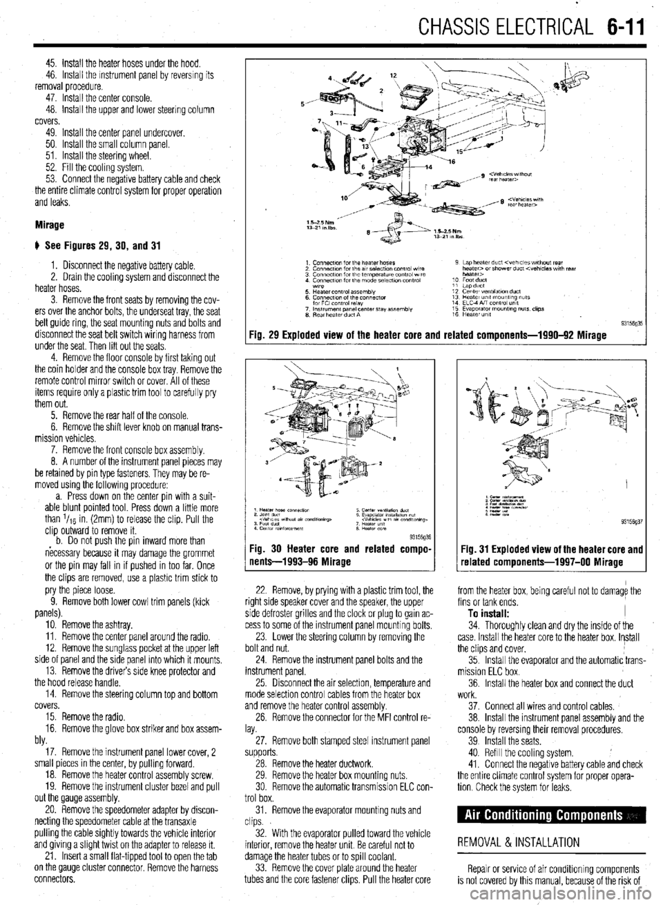
# See Figures 29, 30, and 31
1. Disconnect the negative battery cable.
2. Drain the cooling system and disconnect the
heater hoses.
3. Remove the front seats by removing the cov-
ers over the anchor bolts, the underseat tray, the seat
belt guide ring, the seat mounting nuts and bolts and
disconnect the seat belt switch wiring harness from
under the seat. Then lift out the seats
4. Remove the floor console by first taking out
the coin holder and the console box tray. Remove the
remote control mirror switch or cover. All of these
items require only a plastic trim tool to carefully pry
them out.
5. Remove the rear half of the console.
6. Remove the shift lever knob on manual trans-
mission vehicles.
7. Remove the front console box assembly.
8. A number of the instrument panel pieces may
be retamed by pin type fasteners. They may be re-
moved using the following procedure:
a. Press down on the center pin with a suit-
able blunt pointed tool. Press down a little more
than l/re in. (2mm) to release the clip. Pull the
clip outward to remove it.
b. Do not oush the oin inward more than
necessary because it may damage the grommet
or the pin may fall in if pushed in too far. Once
the clips are removed, use a plastic trim stick to
pry the piece loose.
9. Remove both lower cowl trim panels (kick
panels).
10. Remove the ashtray.
11. Remove the center panel around the radio.
12. Remove the sunglass pocket at the upper left
side of panel and the side panel into which it mounts,
13. Remove the drivers side knee protector and
the hood release handle.
14. Remove the steering column top and bottom
covers.
15. Remove the radio.
16. Remove the glove box striker and box assem-
bly.
17. Remove the instrument panel lower cover, 2
small pieces in the center, by pulling forward.
18. Remove the heater control assembly screw.
19. Remove the instrument cluster bezel and pull
out the Qauge assembly.
20. Remove the speedometer adapter by discon-
necting the speedometer cable at the transaxle
pulling the cable Sightly towards the vehicle interior
and giving a Slight twist on the adapter to release it.
21. Insert a small flat-tipped tool to open the tab
on the QauQe cluster connector. Remove the harness
connectors.
Fig. 29 Exploded view of the heater core and related components-1990-92 Mirage
93l%Q% Fig. 30 Heater core and related compo-
nents-1993-96 Mirage
22. Remove, by prying with a plastic trim tool, the
right side speaker cover and the speaker, the upper
side defroster grilles and the clock or plug to gain ac-
cess to some of the instrument panel mounting bolts.
23. Lower the steering column by removing the
bolt and nut.
24. Remove the instrument panel bolts and the
instrument panel.
25 Drsconnect the air selection, temperature and
mode selection control cables from the heater box
and remove the heater control assembly.
26. Remove the connector for the MFI control re-
lay.
27. Remove both stamped steel instrument panel
supports.
28. Remove the heater ductwork.
29. Remove the heater box mounting nuts.
30 Remove the automatic transmission ELC con-
trol box.
31. Remove the evaporator mounting nuts and
clips.
32. With the evaporator pulled toward the vehicle
interior, remove the heater unit. Be careful not to
damage the heater tubes or to spill coolant.
33. Remove the cover plate around the heater
tubes and the core fastener clips. Pull the heater core 34. Thoroughly clean and dry the inside of the
case. Install the heater core to the heater box. Install
the clips and cover,
35. Install the evaporator and the automatic trans-
mission ELC box.
36. Install the heater box and connect the duct
Fig. 31 Exploded view of the heater core and
related components-1997-00 Mirage
from the heater box, being careful not to damage the
fins or tank ends.
To install: I
work.
37. Connect all wires and control cables,
38. Install the instrument panel assembly and the
console by reversmg their removal procedures.
39 Install the seats.
40. Refill the cooling system.
41. Connect the negative battery cable and check
the entire climate control system for proper opera-
tion Check the system for leaks.
REMOVAL &INSTALLATION
Repair or service of air Conditioning components
is not covered by this manual, because of the risk of
Page 375 of 408

BODYANDTRIM IO-7
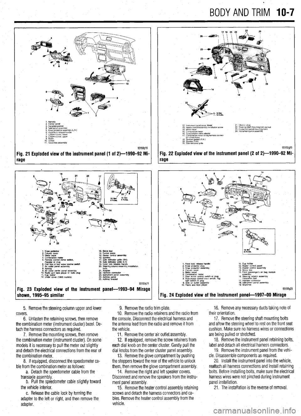
1. Ashtray
2 cenrer DaneI
3. Sunglass pocket
4 Side panel assembly
5 Knee protector assembly (L
6 Hood lock release handle
7 Column cover. lower
8 Column cover. upper
9 Radio
10 Striker
11. Glove box assembly
Fig. 21 Exploded view of the instrument panel (1 of 2)-1990-92 Mi-
rage
1. Knee pmtector
2. Column cover
3. Meter bezel
4. Combination meter
5. Remote control mirror switch.
rhsostat or plug
6. Coin box or rear wper washer switch
7. Aw outlet panel assembly
6. Ashtray
0. Air outlet center panel assembly
10. Radio and tape player or radio plug
11. Cup holder
12. Under COW (1993 models) 14. Comer panel
15. Heater control assembly %.
16. Speaker
17. Side defroster grille (RH)
16. Side defroster grille (LH)
19. Hood lock release handle
20. Ee$ng column assembly mstallation
21. Adapter
22 Harness oonnector
23. Instrument panel assembly
24. Ashtray panel
25. Ashtray bracket
9315og21 Fig. 23 Exploded view of the instrument panel-1993-94 Mirage
shown, 1995-95 similar
5. Remove the steering column upper and lower
covers.
6. Unfasten the retaining screws, then remove
the combination meter (instrument cluster) bezel. De-
tach the harness connectors as required.
7. Remove the mounting screws, then remove
the combination meter (instrument cluster). On some
models it is necessary to pull the meter out slightly
and detach the electrical connections from the rear of
the combination meter.
8. If equipped, disconnect the speedometer ca-
ble from the combination meter as follows:
a. Detach the speedometer cable from the
transaxle assembly.
b. Pull the speedometer cable slightly toward
the vehicle interior.
c. Release the cable lock by turning the
adapter to the left or right, and then remove the
adapter.
18
S-14Nm
7-lOh.lbs.
12 ln~v~rnent panel cover. lower
13 Hearer control assembly w,tallatlon screw
14 Meter bezel
15 Combination meter
16 Speedometer cable adapter
17 Comblnawn meterwr~ng harness connec-
. to1 co”“ectlo”s
16 Speaker amlsh (R H )
19 Speaker RHI e
20 S\de defroster grllla 21 Clock 01 plug
22 Steering shaft mount,ng bolt and nut
23 Ins!rument panel mounting bolts
24 Instrument panel assembly
9315og20 Fig. 22 Exploded view of the instrument panel (2 of 2)-1990-92 Mi-
rage
Fig. 24
1. Hood lock release handle
2. Knee protactor plug
3. Knee protector assembly
4 Column cover
5. Meter bezel
6. Combination meter
7. Door mrror control swich or plug
6. Auto-CNISO control mam swtch. fog
hght swtch M plug
0. Stde av outlet assembly
10 Radio and tape player 11. Cup holder
12. Heater control panel
13. Heater control assembly
14. Glove box
15 Front passenger’s 81, bag module
assembly
16. Steerq column assembly
lnstallatlon bon
17. Harness connector
16. Instrument panel assembly
19 Grommet
Exploded view of the instrument panel-l 997-00 Mirage
9. Remove the radio trim plate.
IO. Remove the radio retainers and the radio from
the console. Disconnect the electrical harness and
the antenna lead from the radio and remove it from
the vehicle.
11. Remove the center air outlet assembly.
12. If equipped, remove the screw retainers from
each dial knob on the center cluster. Gently pull the
dial knobs from the center cluster panel assembly.
13. Remove the glove compartment by pushing
the stoppers toward the rear of the vehicle to unlock
them, then remove the glove compartment assembly.
14. Remove the right and left speaker covers.
Disconnect and remove the speakers from the instru-
ment panel assembly.
15. Remove the heater control assembly retaining
screws and detach the harness connectors and ca-
bles. Remove the heater control assembly from the
vehicle. , 16. Remove any necessary ducts taking note of
their orientation,
17. Remove the steering shaft mounting bolts
and allow the steering wheel to rest on the front seat
cushion, Make sure no harness wires or connections
are being pulled or stretched.
18. Remove the instrument panel retaining bolts,
label and detach all electrical harness connectors.
19. Remove the instrument panel from the vehi-
cle. Disassemble components as required.
20. Install the instrument panel into the vehicle,
reattach all harness connections and install retaining
bolts. Before installing bolts, make sure the electrical
harness wires were not pinched during instrument
panel installation.
21. The installation is the reverse of removal.
Page 377 of 408

c BODYANDTRi'l IO-9
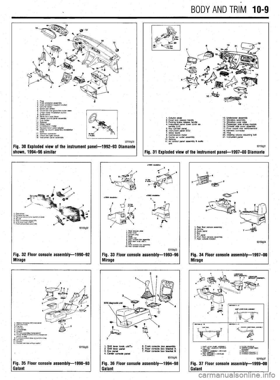
:: k% protector assembly
3. Knee protector support bracket
4. Column cover
5 Glove box striker
6 Glove box and glove box outer case
7 Under cover mstallatmn screw
8. Audio panel
9 Radio and tape player
10 Heater control panel
assembly 11 Cup holder
12. Speaker
13 Meter bezel
14 Combination meter
15 Speeoometer cable adapter
16 %&rrng column assembly rnstallatioh
17 Harness connector
18. Glove box kght swatch
19. Instrument panel assembly
9315og29 Fig. 30 Exploded view of the instrument panel-1992-93 Diamante
shown, 1994796 similar
I Cam holder
2 Console box tray
3 Remote control mrror swatch drcover
1 Berrel
3 Rear cms~ie box assembly
3 Shift lever knob 4vitT>
7 Front eonsale box assembly
Fig. 32 Floor console assembly-1990-92
Yg. 33 Floor console assembly-1993-96
Nlirage
Mirage
1 Manual tmnsaxle shrft lever panel 2 Shrft lever boat 3. cup tray 4 lnnerbdx
6 Lrd assembly
6 Stopper 7 Remote cO”trOned nl,rrorSwl,Ch 8 PowerlFVWECONO (EC01 changeover
12 Bracket Wvcles wrthout addlo)
Fig. 35 Floor console assembly-l 990-93
Galant
4’
2
ia
9315og31 Fig. 31
Exploded view of the instrument
panel-l 997-00 Diamante
1. Column cover
2. Hood lock release handle
3. Parking brake release handle
4. Instrument anal lower cover as-
sembly (LH
P 5. Key cylinder panel
6. instrument panel ECU
7. Meter bezel
0. Combination meter 9. Center air outlet assembly
10. Ashtray
11. Air control panel assembly 8 audio
unit 12. Undercover assembly
13. Glovebox assembly
14. Glovebox outer case
15. Passenger side airbag module
16. Console side cover assemblv
17. Flow carpet rear rainforcem&t
18. Harness connector
19. Plug
20. Steering column mountlng bolt
21. Instrument panel
6 Rear cmsole box es%mbly
7
Shrff lever knob
6. CtQ 9 Front console box assembfk
10. Rear console bracket 9315og33
7 6
1. Shii lever knob &ATT:.
2. Shi lever panel
3. Box panel
4. Center console panel 5. Front console box assembly
6. Floor console box bracket A
7. floar console box bradret B
Fig. 36 Floor console assembly-1994-98
Galant
1. Rear floor console assembly
2. Ashtray
6. Front floor console assembly
7 Rear console bracket
Fig. 34 Floor console assembly-1997-00
Mirage
Fig. 37 Floor console assembly-l 999-00
Galant