1900 MITSUBISHI DIAMANTE wheel size
[x] Cancel search: wheel sizePage 4 of 408
I-4 GENERALINFORMATIONAND MAINTENANCE
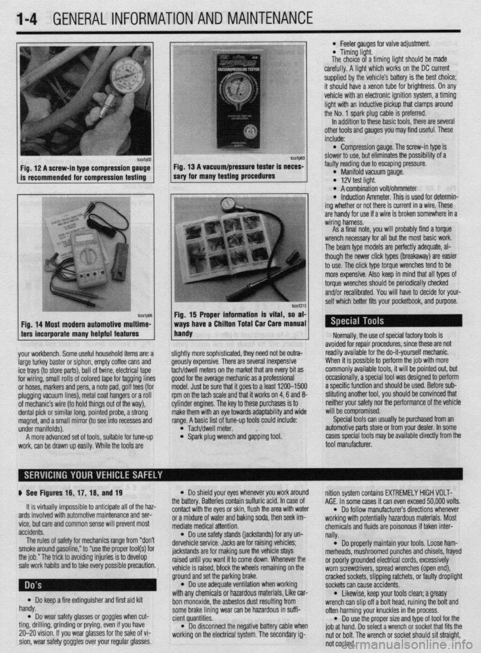
Fig. 12 A screw-in type compression gauge- Fig. 13 A vacuum/pressure tester is neces-
is recommended for compression testing sary for many testing procedures
Fig. 14 Most modern automotive multime-
ters incorporate many helpful features
your workbench. Some useful household items are: a
large turkey baster or siphon, empty coffee cans and
ice trays (to store parts), ball of twine, electrical tape
for wiring, small rolls of colored tape for tagging lines
or hoses, markers and pens, a note pad, golf tees (for
plugging vacuum lines), metal coat hangers or a roll
of mechanic’s wire (to hold things out of the way),
dental pick or similar long, pointed probe, a strong
magnet, and a small mirror (to see into recesses and
under manifolds).
A more advanced set of tools, suitable for tune-up
work, can be drawn up easily. While the tools are
lmvl Fig. 15 Proper information is vital, so at
ways have a Chiiton Total Car Care manua
handy
l Feeler aauoes for valve adiustment
* Timing-light.
The choice of a timing fight should be made
carefully. A light which works on the DC current
supplied by the vehicle’s battery is the best choice;
it should have a xenon tube for brightness. On any
vehicle with an electronic ignition system, a timing
light with an inductive pickup that clamps around
the No. 1 spark plug cable is preferred.
In addition to these basic tools, there are several
other tools and gauges you may find useful. These
include:
l Compression gauge. The screw-in type is
slower to use, but eliminates the possibility of a
fauliy reading due to escaping pressure.
l Manifold vacuum gauge. l 12V test light. l A combination volt/ohmmeter l induction Ammeter. This is used for determin-
ing whether or not there is current in a wire. These
are handy for use if a wire is broken somewhere in a
wiring harness.
As a final note, vou will orobablv find a torque
wrench necessary for all but the most basic work.
The beam type models are perfectly adequate, al-
though the newer click types (breakaway) are easier
to use. The click type torque wrenches tend to be
more expensive. Also keep in mind that all types of
torque wrenches should be periodically checked
and/or recalibrated. You will have to decide for your-
self which better fits your pocketbook, and purpose.
ilightly more sophisticated, they need not be outra-
feously expensive. There are several inexpensive
achldwell meters on the market that are every bit as
Toad for the average mechanic as a professional
nodel. Just be sure that it goes to a least 1200-1500
pm on the tach scale and that it works on 4,6 and 8-
:ylinder engines. The key to these purchases is to
nake them with an eye towards adaptability and wide
ange. A basic list of tune-up tools could include:
l Tach/dwell meter. l Spark plug wrench and gapping tool. Normally, the use of special factory tools is
avoided for repair procedures, since these are not
readily available for the do-it-yourself mechanic.
When it is possible to perform the job with more
commonly available tools, it will be pointed out, but
occasionally, a special tool was designed to perform
a specific function and should be used. Before sub-
stituting another tool, you should be convinced that
neither your safety nor the performance of the vehicle
will be compromised.
Special tools can usually be purchased from an
automotive parts store or from your dealer. In some
cases special tools may be available directly from the
tool manufacturer.
p See Figures 16, 17, 16, and 19
It is virtually impossible to anticipate all of the haz-
ards involved with automotive maintenance and ser-
vice, but care and common sense will prevent most
accidents.
The rules of safety for mechanics range from “don’t
smoke around gasoline,” to “use the proper tool(s) for
the job.” The trick to avoiding injuries is to develop
safe work habits and to take every possible precaution.
Do keep a fire extinguisher and first aid kit
l handy.
Do wear safety glasses or goggles when cut- l ting, drilling, grinding or prying, even if you have
20-20 vision. If you wear glasses for the sake of vi-
sion, wear safety goggles over your regular glasses.
l Do shield your eyes whenever you work around
the battery. Batteries contain sulfuric acid. In case of
contact with the eyes or skin, flush the area with water
or a mixture of water and baking soda, then seek im-
mediate medical attention.
l Do use safety stands (jackstands) for any un-
dervehicle service. Jacks are for raising vehicles;
jackstands are for making sure the vehicle stays
raised until you want it to come down. Whenever the
vehicle is raised, block the wheels remaining on the
ground and set the parking brake.
l Do use adequate ventilation when working
with any chemicals or hazardous materials, Like car-
bon monoxide, the asbestos dust resulting from
some brake lining wear can be hazardous in suffi-
cient quantities.
l Do disconnect the negative battery cable when
working on the electrical system. The secondary ig- nition system contains EXTREMELY HIGH VOLT-
AGE. In some cases it can even exceed 50,000 volts.
l Do follow manufacturer’s directions whenever
working with potentially hazardous materials. Most
chemicals and fluids are poisonous if taken inter-
nally.
l Do properly maintain your tools. Loose ham-
merheads, mushroomed punches and chisels, frayed
or poorly grounded electrical cords, excessively
worn screwdrivers, spread wrenches (open end),
cracked sockets, slipping ratchets, or faulty droplight
sockets can cause accidents.
* Likewise, keep your tools clean; a greasy
wrench can slip off a bolt head, ruining the bolt and
often harming your knuckles in the process.
l Do use the proper size and type of tool for the
job at hand. Do select a wrench or socket that fits the
nut or bolt. The wrench or socket should sit straight,
not cocked.
Page 5 of 408
1-6 GENERALINFORMATIONAND MAINTENANCE
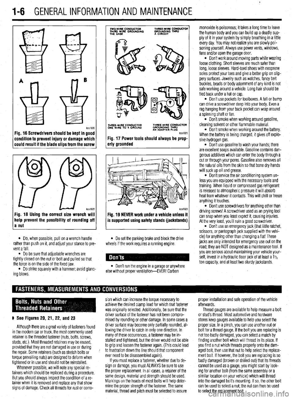
Fig. 16 Screwdrivers should be kept in good
:ondition to prevent injury or damage which
:ould result it the blade slips from the screw
0
0
PP tccs1022 Fig. 16 Using the correct size wrench will
help prevent the possibility of rounding off
a nut
7
lwo.WIRE CouDuClOR TMREE-WIRE CONO”CTOI
MIRD WIRE GROUNDING GROUNDING TNRU
THE CASE A CmxlIT
.
i$Y$$pQ
p-+
TNHREE-WIRE CONDUCTOR THREE-WIRE CONDUCTOR
ONE WIRE TO 4 GROUND GROUNOlNG TMRU
AN ADAPTER PLUG
tccm21
Fig. 17 Power tools should always be prop-
erly grounded
Fig. 19 NEVER work under a vehicle unless it
is supported using safety stands (jackstands)
l Do, when possible, pull on a wrench handle l Do set the parking brake and block the drive
rather than push on it, and adjust your stance to pre-
vent a fall. wheels if the work requires a running engine.
l Do be sure that adjustable wrenches are
tightly closed on the nut or bolt and pulled so that
the force is on the side of the fixed jaw.
l Do strike squarely with a hammer; avoid glanc-
ing blows. l Don’t run the engine in a garage or anywhere
else without proper ventilation-EVER! Carbon monoxide is poisonous; it takes a long time to leave
the human body and you can build up a deadly sup-
ply of it in your system by simply breathing in a !ittle
every day. You may not realize you are slowly poi-
soning yourself. Always use power vents, windows,
fans and/or open the garage door.
l Don’t work around moving parts while wearing
loose clothing. Short sleeves are much safer than
long, loose sleeves. Hard-toed shoes with neoprene
soles protect your toes and give a better grip on slip-
pery surfaces. Jewelry such as watches, fancy belt
buckles, beads or body adornment of any kind is not
safe working around a vehicle. Long hair should be
tied back under a hat or cap.
l Don’t use pockets for toolboxes. A fall or bump
can drive a screwdriver deep into your body. Even a
rag hanging from your back pocket can wrap around
a spinning shaft or fan.
l Don’t smoke when working around gasoline,
cleaning solvent or other flammable material.
l Don’t smoke when workrng around the battery.
When the battery is being charged, it gives off explo-
sive hydrogen gas.
l Don’t use gasoline to wash your hands; there
are excellent soaps available. Gasoline contains dan-
gerous additives which can enter the body through a
cut or through your pores. Gasoline also removes all
the natural oils from the skin so that bone dry hands
will suck up oil and grease.
l Don’t service the air conditioning system un-
less you are equipped with the necessary tools and
trainmg. When liquid or compressed gas refrigerant
is released to atmospheric pressure it will absorb
heat from whatever it contacts. This will chill or freeze
anything it touches.
l Don’t use screwdrivers for anything other than
driving screws! A screwdriver used as an prying tool
can snap when you least expect it, causing injuries.
At the very least, you’ll ruin a good screwdriver.
. Don’t use an emergency jack (that little ratchet,
scissors, or pantograph jack supplied with the vehi-
cle) for anything other than changing a flat! These
jacks are only Intended for emergency use out on the
road; they are NOT designed as a maintenance tool. If
you are serious about mamtaining your vehicle your-
self, invest in a hydraulic floor jack of at least a 1%
ton capacity, and at least two sturdy jackstands.
sion which can increase the torque necessary to proper installation and safe operation of the vehicle
achieve the desired clamp load for which that fastener afterwards.
was originally selected. Additionally, be sure that the Thread gauges are available to help measure a bolt
p See Figures 20, 21, 22, and 23 driver surface of the fastener has not been compro- or stud’s thread. Most automotive and hardware
mised by rounding or other damage. In some cases a stores keep gauges available to help you select the
Although there are a great variety of fasteners found driver surface may become only partially rounded, al- proper size. In a pinch, you can use another nut or
in the modern car or truck, the most commonly used lowing the driver to catch in only one direction. In bolt for a thread gauge. If the bolt you are replacing is
retainer is the threaded fastener (nuts, bolts, screws, many of these occurrences, a fastener may be in- not too badly damaged, you can select a match by
studs, etc.). Most threaded retainers may be reused, stalled and tightened, but the driver would not be able finding another bolt which will thread in its place. If
provided that they are not damaged in use or during to grip and loosen the fastener again. (This could lead you find a nut which threads properly onto the dam-
the repair. Some retainers (such as stretch bolts or J to frustration down the line should that component aged bolt, then use that nut to help select the replace-
torque prevailing nuts) are designed to deform when ever need to be disassembled again). ment bolt If however, the bolt you are replacing is so
tightened or in use and should not be reinstalled. If you must replace a fastener, whether due to de- badly damaged (broken or drilled out) that its threads
Whenever possible, we will note any special re- sign or damage, you must ALWAYS be sure to use cannot be used as a gauge, you might start by look-
tainers which should be replaced during a procedure. the proper replacement In all cases, a retainer of the ing for another bolt (from the same assembly or a
But you should always inspect the condition of a re- same design, material and strength should be used. similar location on your vehicle) which will thread
tainer when It is removed and replace any that show Markings on the heads of most bolts will help deter- into the damaged bolt’s mounting. If so, the other bolt
signs of damage. Check all threads for rust or corro- mine the proper strength of the fastener. The same
can be used to select a nut; the nut can then be used
material, thread and pitch must be selected to assure
to select the replacement bolt.
Page 30 of 408
GENERALINFORMATIONAND MAlNTENANdE 1-31
When rotating “unidirectional tires,” make sure
that they always roll in the same direction. This
means that a tire used on the left side of the vehicle
must not be switched to the right side and vice-versa.
Such tires should only be rotated front-to-rear or
rear-to-front, while always remaining on the same
side of the vehicle. These tires are marked on the
sidewall as to the direction of rotation; observe the
marks when reinstalling the tire(s).
Some styled or “mag” wheels may have different
offsets front to rear. In these cases, the rear wheels
must not be used up front and vice-versa. Further-
more, if these wheels are equipped with unidirectional
tires, they cannot be rotated unless the tire is re-
mounted for the proper direction of rotation.
*The compact or space-saver spare is
strictly for emergency use. it must never be
included in the tire rotation or placed on the
vehicle for everyday use. check the installed tire for any sign of interference
with the body or suspension while the vehicle is stop-
ping, turning sharply or heavily loaded.
Snow Tires
Good radial tires can produce a big advantage in
slippery weather, but in snow, a street radial tire does
not have sufficient tread to provide traction and con-
trol. The small grooves of a street tire quickly pack
with snow and the tire behaves like a billiard ball on a
marble floor, The more open, chunky tread of a snow
tire will self-clean as the tire turns, providing much
better grip on snowy surfaces.
To satisfy municipalities requiring snow tires dur-
ing weather emergencies, most snow tires carry either
an M + S designation after the tire size stamped on
the sidewall, or the designation “all-season.” In gen-
eral, no change in tire size is necessary when buying
snow tires.
Most manufacturers stronqlv recommend the use styled wheels, see if inexpensive steel
wheels are available, Although the look of
the vehicle will change, the expensive
wheels will be protected from salt, curb hits
and pothole damage.
TIRESTORAGE
If they are mounted on wheels, store the tires at
proper inflation pressure. All tires should be kept in a
cool, dry place. If they are stored in the garage or
basement, do not let them stand on a concrete floor;
set them on strips of wood, a mat or a large stack of
newspaper. Keeping them away from direct moisture
is of paramount importance. Tires should not be
stored upright, but in a flat position.
INFLATION & INSPECTION
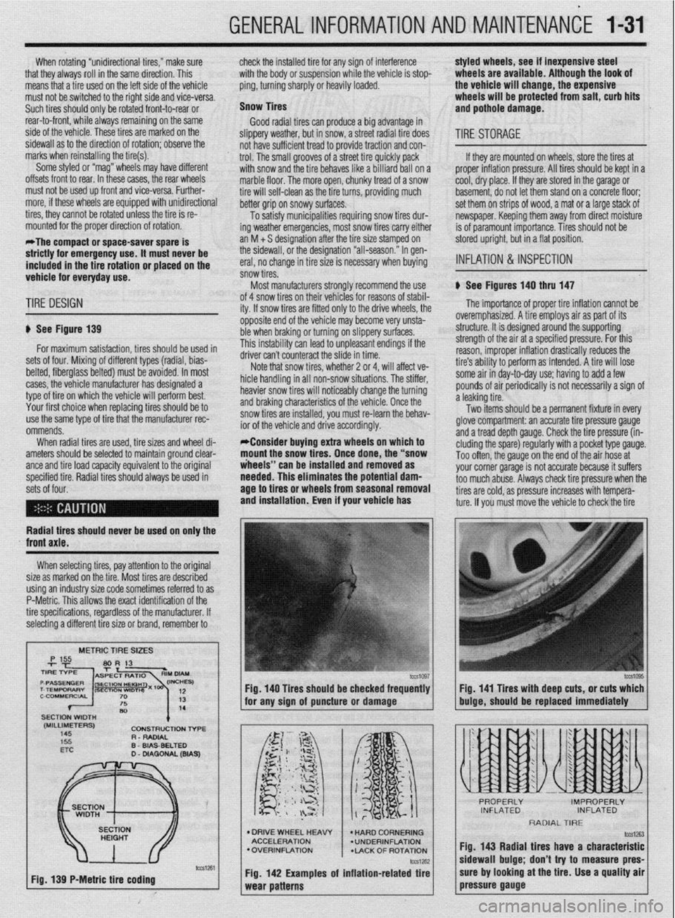
b See Figures 140 thru 147
TIRE DESIGN
p See Figure 139
for maximum satisfaction, tires should be used in
sets of four. Mixing of different types (radial, bias-
belted, fiberglass belted) must be avoided. In most
cases, the vehicle manufacturer has designated a
type of tire on which the vehicle will perform best.
Your first choice when replacing tires should be to
use the same type of tire that the manufacturer rec-
ommends.
When radial tires are used, tire sizes and wheel di-
ameters should be selected to maintain ground clear-
ante and tire load caoacitv eauivalent to the oriainal
specified tire. Radial tiresshould always be used in
sets of four. of 4 snow tires on their
lehicies for reasons of stabil-
ity. If snow tires are fitter
1 only to the drive wheels, the
opposite end of the vehil cle may become very unsta-
ble when braking or turn
ring on slippery surfaces.
This instability can lead to unpleasant endings if the
A*:,,“- r-..l, ^_.. ..& ^_^^, &I.
UIIVU MII I LUUII~~MLL iue slide in time.
Note that snow tires, whether 2 or 4, will affect ve-
hicle handling in all non-snow situations. The stiffer,
heavier snow tires will noticeably change the turning
and braking characteristics of the vehicle. Once the
snow tires are installed, you must re-learn the behav-
ior of the vehicle and drive accordingly.
*Consider buying extra wheels on which to
mount the snow tires. Once done, the “snow
iheeis” can be installed and removed as
needed. This eliminates the potential
dam- age to tires or wheels from seasonal removal
and installation. Even if your vehicle has
lb The importance of proper tire inflation cannot be
overemphasized. A tire employs air as part of its
structure. It is designed around the supporting
strength of the air at a specified pressure. For this
reason, improper inflation drastically reduces the
tire’s ability to perform as intended. A tire will lose
some air in day-to-day use; having to add a few
pounds of air periodically is not necessarily a sign of
a leaking tire.
Two items should be a permanent fixture in every
glove compartment: an accurate tire pressure gauge
and a tread depth gauge. Check the tire pressure (in-
eluding the spare) regularly with a pocket type gauge.
Too often, the gauge on the end of the air hose at
vnr rr corner narane is not accurate because it suffers
~rs check tire oressure when the
Radial tires should never be used on only the
XI I._.
‘-’ --“‘“’ J s too much abuse. Alwa!
tires are cold, as pressure increases with tempera-
ture. If you must move the vehicle to check the tire
front axle.
When selecting tires, pay attention to the original
size as marked on the tire. Most tires are described
using an industry size code sometimes referred to as
P-Metric. This allows the exact identification of the
tire specifications, regardless of the manufacturer. If
selecting a different tire size or brand, remember to
METRIC TIRE SIZES
(MILLIMETERS)
145 CDNStRUCtlDN l-6-E
R - RADIAL
D
WA9
Fig. 139 P-Metric tire coding Fig. 140 Tires should be checked frequently
I I Fig. 141 Tires with deep cuts, or cuts which
for any sion of auncture or damaoe
buioe, should be replaced immediately
l DRIVE WHEEL HEAW
ACCELERATION
l OVERINFLATION
*LACK OF ROTATION
Fig. 142 Examples of inflation-related tire
RADIAL TIRE
fig. 143 Radial tires have a characteristic
sidewall bulge; don’t try to measure pres-
sure by looking at the tire. Use a quality air
pressure gauge
Page 46 of 408
GENERAL INFORMATION AND MAINTENANCE 1-47
ramps are also a handy and safe way to both raise l When the drive wheels are to remain on the
and support the vehicle. Be careful though, some ground, leave the vehicle in gear to help prevent it
ramps may be too steep to drive your vehicle onto
The following safety points cannot be overempha- from rolling.
without scraping the front bottom panels. Never sup-
sized:
l Always use jackstands to support the vehicle
port the vehicle on any suspension member (unless l Always block the opposite wheel or wheels to when you are working underneath. Place the stands
specifically instructed to do so by a repair manual) or
keep the vehicle from rolling off the jack. beneath the vehrcle’s jacking brackets Before climb-
by an underbody panel.
l When raising the front of the vehicle, firmly ap- ing underneath, rock the vehicle a bit to make sure it
ply the parking brake. is firmly supported.
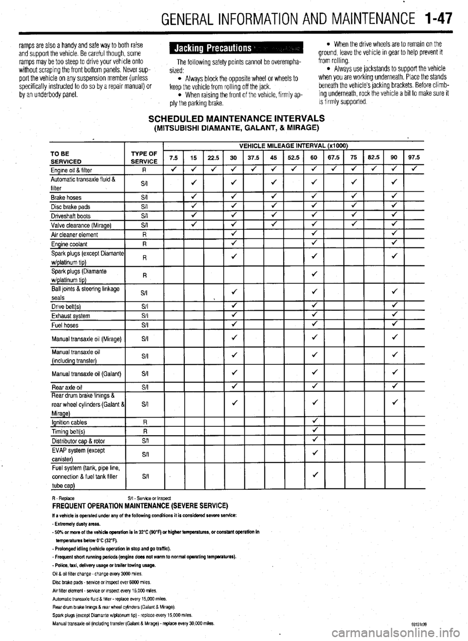
SCHEDULED MAINTENANCE INTERVALS (MITSUBISHI DIAMANTE, GALANT, & MIRAGE)
VEHICLE MILEAGE INTERVAL (x1000)
7.5 15
22.5 30 37.5 45 52.5 60 67.5 75 62.5 90 97.5
J J
J 4 J J 4 4 4 J J
J 4
4
J J J J 4 TO BE
Ball loints &steering linkage
S/I J J J
seals
Dnve belt(s) S/I 4 4 J
Fvha,,rt cvctom $/I
J J J LmI,..“w. “,YL”,‘. Fuel hoses
+
Manual transaxle oil (Galant)
connectlon & fuel tank filler
R. Replace S/I - Sefwce or Inspect FREQUENT OPERATION MAINTENANCE (SEVERE SERVICE) II a vehicle is operated under any of the following conditions it is considered severe service:
- Extremely dusty areas.
- 50% or more of the vehicle operation is in 32% (WF) or higher temperatures, or constant opsralion in
temperatures below 0% (32°F).
- Prolonged idling (vehicle operation in stop and go traffic).
_ Frequent short running periods (engine does not warm to normal operating temfwatures).
- Police, taxi, delivery usage or trailer towing usage.
0118 011 filter change-change every 3CQO miles.
Disc brake pads - sewce or Inspect ever 6COO miles
AN hlter element _ setwe or inspect every 15,000 miles.
Automatic transaxle lluld 8 filter . replace every 15,COO m&s.
Rear drum brake Ikmngs & rear wheel cylinders (Galant & Mirage)
Spark plugs (except Dlamante wlplabnum tip) - replace every 15,COO miles.
Manual transaxle 011 (mcludlng transfer (Galant & Mirage). replace every 30,000 miles.
Page 115 of 408
3-54 ENGINEANDENGINEOVERHALJL
from the, access may be possible (though a little
awkward) to measure the camshaft lobes using a mi-
crometer
In any case, two measurements are necessary for
each lobe. Measurement Y or the total LOBE HEIGHT
and measurement X or the total LOBE WIDTH. To
find the lobe lift, you simply subtract X from Y (sub-
tract the width from the height).
Note each measurement, then make your calcula-
tion to determine the lift. Note the final results and re-
peat the process on the remaining camshaft lobes.
Finally, you should compare your results to the spec-
ifications charts and decide if a new camshaft is in
your future.
REMOVAL &INSTALLATION
2.OL and 2.4L Engines
p See Figure 214
*A special oil seal guide tool, 18998285,
and a plug cap socket tool, MD998182, or ex-
act equivalents are needed to complete this
operation.
1. Disconnect the negative battery cable.
2. Raise and safely support the vehicle.
3. Drain the engine oil.
The EPA warns that prolonged contact with
used engine oil may cause a number of skin
disorders, including cancer! You should
make every effort to minimize your exposure
to used engine oil. Protective gloves should
be worn when changing the oil. Wash your
hands and any other exposed skin areas as
soon as possible after exposure to used en-
gine oil. Soap and water, or waterless hand
cleaner should be used.
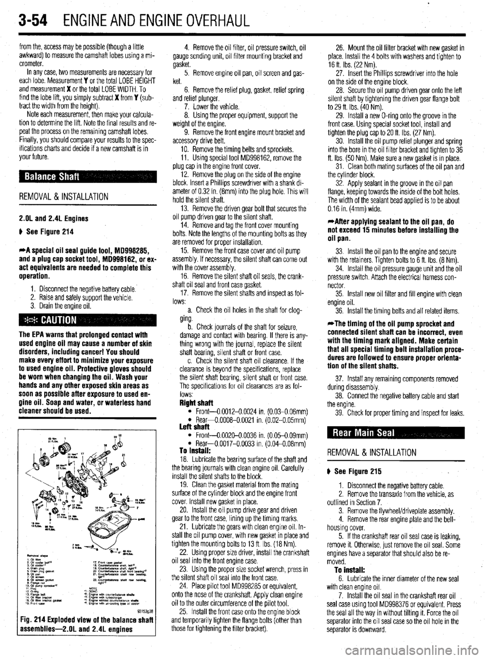
93153g3
:ig. 214 Exploded view of the balance shaf
assemblies-2.01 and 2.4L enoines
4. Remove the oil filter, oil pressure switch, oil
gauge sending unit, oil filter mounting bracket and
gasket.
5. Remove engine oil pan, oil screen and gas-
ket.
6. Remove the relief plug, gasket, relief spring
and relref plunger.
7. Lower the vehicle.
8. Using the proper equipment, support the
weight of the engine.
9. Remove the front engine mount bracket and
accessory drive belt,
10. Remove the timing belts and sprockets.
11. Using special tool MD998162, remove the
plug cap in the engine front cover.
12. Remove the plug on the side of the engine
block. Insert a Phillips screwdriver with a shank di-
ameter of 0.32 in. (8mm) into the plug hole. This will
hold the silent shaft.
13. Remove the driven gear bolt that secures the
oil pump driven gear to the silent shaft.
14. Remove and tag the front cover mounting
bolts. Note the lengths of the mounting bolts as they
are removed for proper installation.
15. Remove the front case cover and oil pump
assembly. If necessary, the silent shaft can come out
with the cover assembly.
16. Remove the silent shaft oil seals, the crank-
shaft oil seal and front case gasket
17. Remove the silent shafts and inspect as fol-
lows:
a. Check the oil holes in the shaft for clog-
ging.
b. Check journals of the shaft for seizure,
damage and contact with bearing. If there is any-
thing wrong with the journal, replace the silent
shaft bearing, silent shaft or front case.
c. Check the silent shaft oil clearance. If the
clearance is beyond the specifications, replace
the silent shaft bearing, silent shaft or front case.
The specifications for oil clearances are as fol-
lows
Right shaft l Front-0.0012-0.0024 in. (0.030.06mml l Rear+0.0008-0.0021 in. (6.02-O 05mm) Left shaft l Front-0.002&0.0036 in. (0.05-0.09mm) l Rear-O.0017-O.0033 in. (0.04-0.08mm) To install: 18. Lubricate the bearing surface of the shaft and
the bearing journals with clean engine oil. Carefully
install the silent shafts to the block.
19. Clean the gasket material from the mating
surface of the cylinder block and the engine front
cover. Install new gasket in place.
20. Install the oil pump drive gear and driven
gear to the front case, lining up the timing marks.
21. Lubricate the gears with clean engine oil. In-
stall the oil pump cover, with new gasket in place and
tighten the mounting bolts to 13 ft. Ibs. (18 Nm).
22. Using proper size driver, install the crankshaft
oil seal into the front engine case.
23. Using the proper size socket wrench, press in
the silent shaft oil seal into the front case.
24. Place pilot tool MD998285 or equivalent,
onto the nose of the crankshaft. Apply clean engine
oil to the outer circumference of the pilot tool.
25. Install the front case onto the engine block
and temporarily tighten the flange bolts (other than
those for tightening the filter bracket). 26. Mount the oil filter bracket with new gasket in
place. Install the 4 bolts with washers and tighten to
16 ft Ibs. (22 Nm).
27. Insert the Phillips screwdriver into the hole
on the side of the engine block.
28. Secure the oil pump driven gear onto the left
silent shaft by tightening the driven gear flange bolt
to 29 ft. Ibs. (40 Nm).
29. Install a new O-ring onto the groove in the
front case. Using special socket tool, install and
tighten the plug cap to 20 ft. Ibs (27 Nm).
30. Install the oil pump relief plunger and spring
into the bore in the oil filter bracket and tighten to 36
ft. Ibs. (50 Nm). Make sure a new gasket is in place.
31. Clean both mating surfaces of the oil pan and
the cylinder block.
32. Apply sealant in the groove in the oil pan
flange, keeping towards the inside of the bolt holes.
The width of the sealant bead applied is to be about
0.16 in. (4mm) wide.
*After applying sealant to the oil pan, do
not exceed 15 minutes before installing the
oil pan.
33. Install the oil pan to the engine and secure
with the retainers. Tighten bolts to 6 ft. Ibs. (8 Nm).
34. Install the oil pressure gauge unit and the oil
pressure switch. Attach the electrical harness con-
nector
35. Install new oil filter and fill engine with clean
engine oil.
36. Install the timing belts and all related items,
*The timing of the oil pump sprocket and
connected silent shaft can be incorrect, even
with the timing mark aligned. Make certain
that all special timing belt installation proce-
dures are followed to ensure proper orienta-
tion of the silent shafts.
37. Install any remaining components removed
during disassembly.
38. Connect the negative battery cable and start
the engine.
39. Check for proper timing and inspect for leaks.
REMOVAL &INSTALLATION
p See Figure 215
1. Disconnect the negative battery cable.
2. Remove the transaxle from the vehicle, as
outlined in Section 7.
3. Remove the flywheel/driveplate assembly.
4. Remove the rear engine plate and the bell-
housing cover.
5. If the crankshaft rear oil seal case is leaking,
remove it. Otherwise, just remove the oil seal. Some
engines have a separator that should also be re-
moved.
To install: 6. Lubricate the inner diameter of the new seal
with clean engine oil.
7. Install the oil seal in the crankshaft rear oil
seal case using tool MD998376 or equivalent. Press
the seal all the way in without tilting it. Force the oil
separator into the oil seal case so the oil hole in the
separator is downward.
Page 120 of 408
ENGINEAND ENGINEOVERHAUL 3-59
Most of the cleaning process can be carried out
with common hand tools and readily available sol-
vents or solutions. Carbon deposits can be chipped
away using a hammer and a hard wooden chisel. Old
gasket material and varnish or sludge can usually be
removed using a scraper and/or cleaning solvent. Ex-
tremely stubborn deposits may require the use of a
power drill wrth a wire brush. If using a wire brush,
use extreme care around any critical machined sur-
faces (such as the gasket surfaces, bearing saddles,
cylinder bores, etc.). USE OF A WIRE BRUSH IS NOT
RECOMMENDED ON ANY ALUMINUM COMPO-
NENTS Always follow any safety recommendations
given by the manufacturer of the tool and/or solvent.
You should always wear eye protection during any
cleaning process involvrng scraping, chipping or
spraying of solvents.
An alternative to the mess and hassle of cleaning
the parts yourself is to drop them off at a local garage
or machine shop. They will, more than likely, have
the necessary equrpment to properly clean all of the
parts for a nominal fee.
Always wear eye protection during any clean-
ing process involving scraping, chipping or
spraying of solvents.
Remove any oil galley plugs, freeze plugs and/or
pressed-in bearings and carefully wash and degrease
all of the engine components including the fasteners
and bolts. Small parts such as the valves, springs,
etc., should be placed in a metal basket and allowed
to soak. Use pipe cleaner type brushes, and clean all
passageways in the components. Use a ring ex-
pander and remove the rings from the pistons. Clean
the piston ring grooves with a special tool or a piece
of broken ring Scrape the carbon off of the top of the
piston. You should never use a wire brush on the
pistons. After preparing all of the piston assemblies
in this manner, wash and degrease them again.
Use extreme care when cleaning around the
cylinder head valve seats. A mistake or slip
may cost you a new seat.
When cleaning the cylinder head, remove carbon
from the combustron chamber with the valves in-
stalled. This will avoid damaging the valve seats.
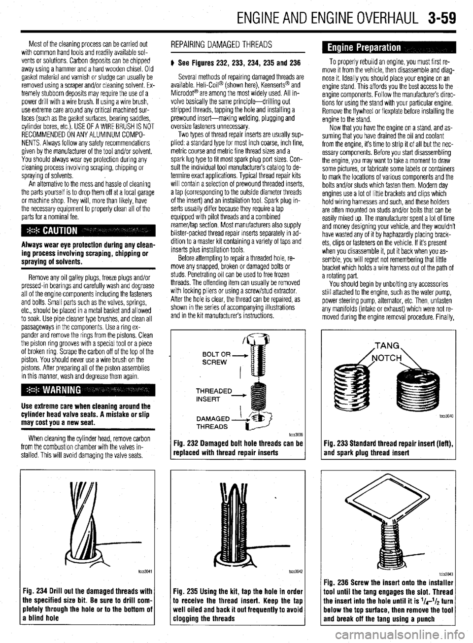
:ig. 234 Drill out the damaged threads with
he specified size bit. Be sure to drill corn.
rletely through the hole or to the bottom oi
I blind hole REPAIRING DAMAGEDTHREADS
# See Figures 232, 233, 234, 235 and 236
Several methods of repairing damaged threads are
available Heli-Coil@ (shown here), Keenserts@ and
Microdop are among the most widely used. All in-
volve basically the same principle-drilling out
stripped threads, tapping the hole and installing a
prewound insert-making welding, plugging and
oversize fasteners unnecessary.
Two types of thread repair inserts are usually sup-
plied: a standard type for most inch coarse, rnch fine,
metric course and metrrc fine thread sizes and a
spark lug type to fit most spark plug port sizes. Con-
sult the individual tool manufacturers catalog to de-
termine exact applications. Typical thread repair kits
will contain a selection of prewound threaded inserts,
a tap (corresponding to the outside diameter threads
of the insert) and an installation tool. Spark plug in-
serts usually differ because they require a tap
equipped wrth pilot threads and a combined
reamer/tap section. Most manufacturers also supply
blister-packed thread repair Inserts separately in ad-
dition to a master kit containing a variety of taps and
inserts plus installation tools
Before attempting to repair a threaded hole, re-
move any snapped, broken or damaged bolts or
studs. Penetrating oil can be used to free frozen
threads. The offending item can usually be removed
with locking pliers or using a screw/stud extractor.
After the hole is clear, the thread can be reparred, as
shown in the series of accompanying illustrations
and in the krt manufacturers instructions.
THREADED
lCCS3039
replaced with thread repair inserts
:ig. 235 Using the kit, tap the hole in order
o receive the thread insert. Keep the tap
veil oiled and back it out frequently to avoid
:logging the threads
To properly rebuild an engine, you must first re-
move it from the vehicle, then disassemble and diag-
nose it. Ideally you should place your engine on an
engine stand. This affords you the best access to the
engine components. Follow the manufacturers direc-
tions for using the stand with your particular engine.
Remove the flywheel or flexplate before installing the
engine to the stand.
Now that you have the engine on a stand, and as-
suming that you have drained the oil and coolant
from the engine, it’s time to strip it of all but the nec-
essary components. Before you start disassembling
the engine, you may want to take a moment to draw
some pictures, or fabricate some labels or containers
to mark the locations of various components and the
bolts and/or studs which fasten them. Modern day
engines use a lot of little brackets and clips which
hold wiring harnesses and such, and these holders
are often mounted on studs and/or bolts that can be
easily mixed up. The manufacturer spent a lot of time
and money designing your vehicle, and they wouldn’t
have wasted any of it by haphazardly placing brack-
ets, clips or fasteners on the vehicle. If it’s present
when you disassemble it, put it back when you as-
semble, you will regret not remembering that little
bracket which holds a wire harness out of the path of
a rotating part.
You should begin by unbolting any accessories
still attached to the engine, such as the water pump,
power steering pump, alternator, etc. Then, unfasten
any manifolds (intake or exhaust) which were not re-
moved during the engine removal procedure. Finally,
Fig. 233 Standard thread repair insert (left),
and spark plug thread insert
im3043 Fig. 236 Screw the insert onto the installer
1001 until the tang engages the slot. Thread
‘he insert into the hole until it is l/4-l/~ turn
lelow the top surface, then remove the tool
and break off the tano usina a uunch
Page 126 of 408
I)
ENGINEANDENGINEOVERHAUL 3-65
10. Install the camshaft(s), rockers, shafts and
any other components that were removed for disas-
sembly.
GENERAL INFORMATION ways number 1. However, depending on the engine
placement, the front of the engine could either be the
flywheel or damper/pulley end. Generally the front of
the engine faces the front of the vehicle. Use a num-
ber punch or scribe and also mark the main bearing
caps from front to rear with the front most cap being
number 1 (if there are five caps, mark them 1 through
5, front to rear).
A thorough overhaul or rebuild of an engine block
would include replacing the pistons, rings, bearings,
timing belt/chain assembly and oil pump. For OHV
engines also include a new camshaft and lifters. The
block would then have the cylinders bored and honed
oversize (or if using removable cylinder sleeves, new
sleeves installed) and the crankshaft would be cut
undersize to provide new wearing surfaces and per-
feet clearances. However, your particular engine may Take special care when pushing the connect-
ing rod up from the crankshaft because the
sharp threads of the rod bolts/studs will
score the crankshaft journal. Insure that spe-
cial plastic caps are installed over them, or
cut two pieces of rubber hose to do the
same.
Again, rotate the engine, this time to position the
number one cylinder bore (head surface) up. Turn the
crankshaft until the number one piston is at the bot-
tom of its travel, this should allow the maximum ac-
cess to its connecting rod. Remove the number one
connecting rods fasteners and cap and place two
lengths of rubber hose over the rod bolts/studs to
protect the crankshaft from damage. Using a sturdy
wooden dowel and a hammer, push the connecting
rod up about 1 in. (25mm) from the crankshaft and
remove the upper bearing insert. Continue pushing
or tapping the connecting rod up until the piston
rings are out of the cylinder bore. Remove the piston
and rod by hand, put the upper half of the bearing in-
sert back into the rod, install the cap with its bearing
insert installed, and hand-tighten the cap fasteners. If
the parts are kept in order in this manner, they will
not get lost and you will be able to tell which bear-
ings came form what cylinder if any problems are
discovered and diagnosis is necessary. Remove all
the other piston assemblies in the same manner. On
V-style engines, remove all of the pistons from one
bank, then reposition the engine with the other cylin-
der bank head surface up, and remove that banks nis-
prevent the assemblies from being removed,
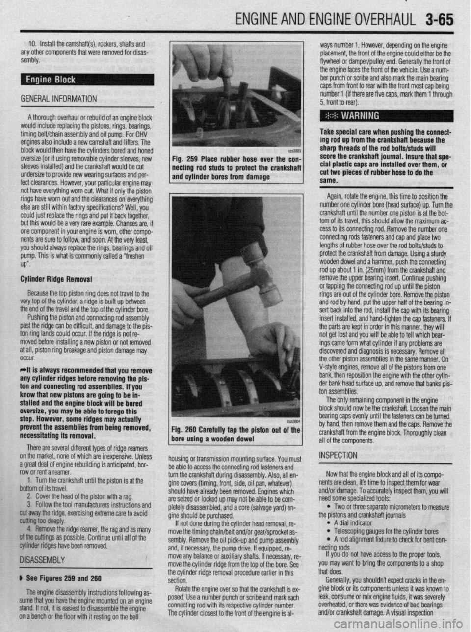
necessitating its removal. Fig. 260 Carefully tap the piston out of the
bore using a wooden dowel
There are several different types of ridge reamers
on the market, none of which are inexpensive, Unless
.3 “me.+ ,-ins, rdnnn;nn mh~lil.-linn ;I nn+:n:nnL.* l.^W
a ylwx “Gal “I cllylllc Ir;““ll”llly 13 dllLILlpxC”, ““I- row or rent a reamer.
1. Turn the crankshaft until the piston is at the
bottom of its travel.
2. Cover the head of the piston with a rag.
3. Follow the tool manufacturers instructions and housing or transmission mounting surface. You must
1 as many
II of the
~1SA~E~BLY
b See Figures 259 and 260
The engine disassembly instructions following as-
sume that you have the engine mounted on an engine
stand. If not, it is easiest to disassemble the engine
on a bench or the floor with it resting on the bell be able to access the connecting rod fasteners and
turn the crankshaft during disassembly. Also, all en-
gine covers (timing, front, side, oil pan, whatever)
should
are sei2
nletelv have already been removed. Engines which
,ed or locked up may not be able to be com-
r’-‘-‘, disassembled, and a core (salvage yard) en-
gine sh ould be purchased.
If no
t done during the cylinder head removal, re-
move the timing chain/belt and/or gear/sprocket as-
sembly. Remove the oil pick-up and pump assembly
and, if necessary, the pump drive. If equipped, re-
move any balance or auxiliary shafts. If necessary, re-
move the cylinder ridge from the top of the bore. See
the cylinder ridge removal procedure earlier in this
section.
Rotate the engine over so that the crankshaft is ex-
posed. Use a number punch or scribe and mark each
connecting rod with its respective cylinder number.
The cylinder closest to the front of the engine is al- cut away the ridge, exercising extreme care to avoid
~ ioo deepfy.
4. Remove the ridge reamer, the rag and
armings as possible. Continue until a
biter ridges have been removed. ton assemblies.
The only remaining component in the engine
block should now be the crankshaft. Loosen the main
bearing caps evenly until the fasteners can be turned
by hand, then remove them and the caps. Remove the
crankshaft from the engine block. Thoroughly clean
all of the components.
INSPECTION
Now that the engine block and all of its compo-
nents are clean, it’s time to inspect them for wear
and/or damage. To accurately inspect them, you will
need some specialized tools:
l Two or three separate micrometers to measure
the prstons and crankshaft journals
l A dial indicator l Telescoping gauges for the cylinder bores l A rod alignment fixture to check for bent con-
netting rods
If you do not have access to the proper tools,
you may want to bring the components to a shop
that does.
Generally, you shouldn’t expect cracks in the en-
gine block or its components unless it was known to
leak, consume or mix engine fluids, it was severely
overheated, or there was evidence of bad bearings
and/or crankshaft damage. A visual inspection
Page 281 of 408
7-2 'DRIVETRAIN
Because of the way an internal combustron engine
breathes, it can produce torque, or twisting force,
only within a narrow speed range. Most modern,
overhead valve pushrod engines must turn at about
2500 rpm to produce their peak torque By 4500 rpm
they are producrng so lrttle torque that contrnued in-
creases in engine speed produce no power increases.
The torque peak on overhead camshaft engines IS
generally much higher, but much narrower.
The manual transaxle and clutch are employed to
vary the relationship between engine speed and the
speed of the wheels so that adequate engine power can
be produced under all crrcumstances. The clutch al-
lows engine torque to be applied to the transaxle input
shaft gradually, due to mechanical slippage. Conse-
quently, the vehicle may be started smoothly from a
full stop The transaxle changes the ratio between the
rotating speeds of the engine and the wheels by the
use of gears. The gear ratios allow full engine power to
be applied to the wheels during acceleration at low
speeds and at highway/passing speeds.
In a front wheel drive transaxle, power is usually
transmitted from the input shaft to a mainshaft or out-
put shaft located slightly beneath and to the side of
the input shaft. The gears of the mainshaft mesh with
gears on the input shaft, allowing power to be carried
from one to the other. All forward gears are in con-
stant mesh and are free from rotating with the shaft
unless the synchronizer and clutch IS engaged. Shaft-
ing from one gear to the next causes one of the gears
to be freed from rotating with the shaft and locks an-
other to it. Gears are locked and unlocked by internal
dog clutches which slide between the center of the
gear and the shaft. The forward gears employ syn-
chronizers; friction members which smoothly bring
gear and shaft to the same speed before the toothed
dog clutches are engaged.
SHIFT LINKAGE
1. Disconnect the shift linkage from the transaxle.
2. On the transaxle, put select lever in N and
move the shift lever in
4th gear. Depress the clutch,
if necessary, to shift.
3. Move the shift lever in the vehicle to the
4th gear position until it contacts the stop.
4. Turn the adjuster turnbuckle so the shift cable
eye aligns with the eye in the gear shift lever. When
installing the cable eye, make sure the flange side of
the plastic bushing at the shift cable end is on the
cotter pin side.
5 The cables should be adjusted so the clear-
ance between the shift lever and the 2 stoppers are
equal when the shift lever IS moved to 3rd and 4th
gear. Move the shift lever to each positron and check i
that the shifting is smooth
REMOVAL &INSTALLATION
1, Disconnect the negative battery cable 2. Remove any components necessary to access
the back-up light switch.
3. Unplug the back-up light switch connector.
4. Remove the switch from the case using the ap-
propriate size socket and drive tool.
To install: 5. Install the switch and tighten it to 22-25 ft. Ibs.
(30-35 Nm).
6. Attach the back-up light switch connector
7. Install any components removed to access the
back-up light switch
8. Connect the negative battery cable.
REMOVAL & INSTALLATION
Mirage
*If the vehicle is going to be roiled while the
halfshafts are out of the vehicle, obtain 2 outer
CV-joints or proper equivalent tools and install
to the hubs. If the vehicle is rolled without the
proper torque applied to the front wheel bear-
ings, the bearings will no longer be usable.
*The suspension components should not be
tightened until the vehicles weight is resting
on the ground.
1. Remove the battery and battery tray.
2. Remove the air cleaner assembly and vacuum
hoses.
3. Note the locations and disconnect the shifter
cables.
4. If equipped with 1.61 engine, remove the ten-
sion rod.
5. Detach the backup lamp switch connector,
speedometer cable connection and remove the starter
motor.
6. Raise the vehicle and support safely.
7. Remove the front wheels and the inner wheel
panels.
8. Remove the undercover and splash pan.
9. Drain the transaxle oil into a suitable con-
tainer
10. Support the engine and remove the cross-
member.
11. Remove the upper transaxle mounting bolt
and bracket.
12 Disconnect the stabilizer bar, tie rod ends and
the lower ball joint connections.
13 Remove the clutch release cylinder and clutch
oil line bracket. Do not disconnect the fluid lines and
secure the slave cylinder with wire.
14 Disconnect the clutch cable, if equipped with
cable controlled clutch system.
15. Remove the halfshafts by inserting a prybar
between the transaxle case and the driveshaft and
prying the shaft from the transaxle. Do not pull on the
driveshaft Doing so damages the inboard joint. Do
not insert the prybar so far the oil seal in the case is
damaged.
*It is not necessary to disconnect the half-
shafts from the steering knuckle. Remove the
shaft with the hub and knuckle as an assem-
bly. Tie the shafts aside. Note the circle clip
on the end of the inboard shafts should not
be reused.
16. Remove the bellhousing lower cover.
17 Remove the transaxle to engine bolts and
lower the transaxle from the vehrcle.
To install:
*When installing the transaxle, be sure to
align the splines of the transaxle with the
clutch disc.
18 Install the transaxle to the engine and install
the mounting bolts. Tighten the bolts to 31-40 ft. Ibs.
(43-55 Nm) on 1990-92 models and 35 ft. Ibs. (48
Nm) on 1993-00 models.
19 Install the bellhousing cover.
*When installing the halfshafts, use new
circlips on the axle ends. Care must be taken
to ensure that the oil seal lip of the transaxle
is not damaged by the serrated part of the
driveshaft.
20. Install and fully seat the halfshafts into the
transaxle.
21. Install the slave cylinder.
22. Connect the ball joints, tie rod ends and the
stabilizer bar connections.
23. Install the upper transaxle mounting bracket
and bolt.
24. Install the crossmember.
25. Install the undercover.
26. Install the upper transaxle-to-engine mount-
ing bolts, Tighten the bolts to 31-40 ft. Ibs. (43-55
Nm) on 199C-92 models and 35 ff. Ibs. (48 Nm) on
1993-00 models.
27. Install the starter motor.
28 Connect the backup light switch connector
and speedometer cable.
29 Connect and adjust the shifter cables.
30 Install the air cleaner assembly.
31. Install the front wheels.
32 Make sure the vehicle is level when refilling
the transaxle Use Hypoid gear oil or equivalent, GL-
4 or higher.
33. Connect the negative battery cable and check
the transaxle for proper operation. Make sure the re-
verse lights operate when in reverse.
Galant
1999-93 MODELS
rlf the vehicle is going to be rolled on its
wheels while the halfshafts are out of the ve-
hicle, obtain two outer CV-joints or proper
equivalent tools and install to the hubs. If the
vehicle is rolled without the proper torque
applied to the front wheel bearings, the bear-
ings will no longer be usable.
1. Remove the battery and the air intake hoses.
2. If equipped with Active-ECS, unplug the
compressor wiring.
3. Remove the auto-cruise actuator and under-
hood bracket, located on the passenger side inner
fender well.
4. Drain the transaxle and transfer case fluid, if
equipped, into a suitable waste container.
5. Remove the retainer bolt and pull the
speedometer cable from the transaxle assembly.
6. Remove the cotter pin securing the select and
shift cables and remove the cable ends from the
transaxle.